Sign In
Upload
Manuals
Brands
Keysight Manuals
Measuring Instruments
34420A
Keysight 34420A Manuals
Manuals and User Guides for Keysight 34420A. We have
2
Keysight 34420A manuals available for free PDF download: User Manual, Service Manual
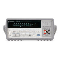
Keysight 34420A User Manual (307 pages)
Nano Volt/Micro Ohm Meter
Brand:
Keysight
| Category:
Measuring Instruments
| Size: 3 MB
Table of Contents
Safety Symbols
3
Waste Electrical and Electronic Equipment (WEEE) Directive
6
Product Category
6
Safety Considerations
8
Measurement Category <Valid for HH UG Only - Remove this
9
Environmental Conditions
10
Regulatory Information
11
Safety Compliance
11
EMC Compliance
11
Regulatory Markings
12
Sales and Technical Support
13
Table of Contents
15
1 Quick Start
24
To Prepare the Meter for Use
25
If the Meter Does Not Turn on
26
To Adjust the Carrying Handle
28
To Make Input Connections
29
To Measure Voltage
31
To Measure Temperature with Thermistors
32
To Measure Temperature with Rtds
33
To Measure Temperature with Thermocouples
34
To Select a Range
35
To Set the Number of Digits
36
To Set the Integration Time
37
Front-Panel Display Formats
38
To Rack Mount the Meter
39
Front-Panel Operation
42
Front-Panel Menu Reference
43
A Front-Panel Menu Tutorial
47
To Select an Input Channel
56
To Select a Range
57
To Set or Change the Number of Digits
58
To Set the Integration Time
59
To Make Null (Relative) Measurements
60
To Store Minimum and Maximum Readings (Stats)
61
To Trigger the Meter
63
To Use Reading Hold
64
To Make Voltage Ratio and Difference Measurements
65
To Use Reading Memory
66
3 Features and Functions
69
General Measurement Configuration
72
Input Filters
72
Integration Time
75
Reducing Measurement Noise
76
Number of Digits Displayed
78
Ranging
80
Overload Detection
81
Voltage Measurement Configuration
82
Input Channels
82
Resistance Measurement Configuration
85
Temperature Measurement Configuration
88
Measurement Units
88
RTD Measurements
89
Thermistor Measurements
89
Thermocouple Measurements
90
Math Operations
91
Null (Relative) Operation
94
Reading Hold
96
Triggering
97
Trigger Source Choices
99
The Wait-For-Trigger State
102
Halting a Measurement in Progress
102
Number of Samples
103
Number of Triggers
103
Trigger Delay
104
Automatic Trigger Delays
106
System-Related Operations
107
Reading Memory
107
Error Conditions
108
Self-Test
109
Display Control
110
Comma Separators
111
Firmware Revision Query
111
SCPI Language Version
112
Voltmeter Complete Terminal
113
External Trigger Terminal
114
Chart Output (Analog Output)
115
Chart Rollover
117
Remote Interface Configuration
119
Remote Interface Selection
119
GPIB Address
120
Baud Rate Selection (RS-232)
121
Parity Selection (RS-232)
122
Programming Language Selection
123
Connection to a Terminal or Printer (RS-232)
124
Calibration
125
Calibration Security
125
Calibration Count
128
Calibration Message
129
Defaults, Power-On and Reset States
130
4 Remote Interface Reference
135
Command Summary
137
Simplified Programming Sequence
146
Using the Measure? Command
148
Using the Configure Command
148
Using the Range and Resolution Parameters
148
Using the READ? Command
149
Using the Initiate and Fetch? Commands
150
The Measure? and Configure Commands
153
Setting the Function, Range, and Resolution
156
Selecting the Input Channel
159
Special Resistance Measurement Commands
160
Temperature Measurement Commands
161
Null (Relative) Commands
164
Input Filter Commands
166
Math Operation Commands
168
Statistics Operation Commands (Average)
169
Scale Operation Commands
170
Triggering
171
The Wait-For-Trigger State
173
Triggering Commands
174
Chart Output (Analog Out) Commands
176
System-Related Commands
177
The SCPI Status Model
179
What Is an Event Register
179
What Is an Enable Register
179
What Is a Condition Register
180
SCPI Status System
181
The Status Byte
182
Using Service Request (SRQ) and Serial POLL
183
Using *STB? to Read the Status Byte
184
To Interrupt Your Bus Controller Using SRQ
184
To Determine When a Command Sequence Is Completed
184
How to Use the Message Available Bit (MAV)
185
Using *OPC to Signal When Data Is in the Output Buffer
185
The Standard Event Register
186
The Questionable Data Register
187
The Operational Status and Condition Registers
188
Status Reporting Commands
190
Calibration Commands
193
RS-232 Interface Configuration
195
RS-232 Configuration Overview
195
RS-232 Data Frame Format
196
Connection to a Computer or Terminal
196
Connection to a Printer
198
DTR / DSR Handshake Protocol
198
RS-232 Troubleshooting
199
RS-232 Interface Commands
201
An Introduction to the SCPI Language
202
SCPI Data Types
204
Input Message Terminators
205
Output Data Formats
206
Using Device Clear to Halt Measurements
207
TALK ONLY for Printers
208
To Set the GPIB Address
209
To Select the Remote Interface
211
To Set the Baud Rate
213
To Set the Parity
215
To Select the Programming Language
217
Alternate Programming Language Compatibility
219
Specific Issues
219
SCPI Compliance Information
220
IEEE-488 Compliance Information
223
5 Error Messages Error Messages
226
Execution Errors
227
Self-Test Errors
234
Calibration Errors
236
6 Application Programs
240
HP BASIC Language Programs
241
HP BASIC/GPIB Program Example 1
241
HP BASIC/GPIB Program Example 2
241
HP BASIC/GPIB Program Example 3
242
HP BASIC/GPIB Program Example 4
244
RS-232 Operations with Quickbasic
249
Microsoft Visual Basic Language Program
251
C Language Programs
258
Compiling and Linking a C Program
258
C/GPIB Example 1
260
C/GPIB Example 2
262
C/GPIB Program Example 3
266
Microsoft Excel Macro Example
270
Macro Comments
271
7 Measurement Tutorial
276
Measurement Techniques and Sources of Error
277
Voltage Measurements
277
Resistance Measurements
287
Temperature Measurements
292
Cleaning the Connector Contacts
301
Advertisement
Keysight 34420A Service Manual (130 pages)
Nano Volt/ Micro Ohm Meter
Brand:
Keysight
| Category:
Measuring Instruments
| Size: 3 MB
Table of Contents
Service Guide
2
Copyright Notice
3
Warranty
3
Safety Information
3
Safety Symbols
4
Safety Considerations
5
Environmental Conditions
6
Waste Electrical and Electronic Equipment (WEEE) Directive 2002/96/ EC
7
Product Category
7
Sales and Technical Support
7
The Front-Panel at a Glance
9
The Front-Panel Menu at a Glance
10
Display Annunciators
12
The Rear Panel at a Glance
13
In this Book
14
Table of Contents
16
Quick Start
27
To Prepare the Meter for Use
28
If the Meter Does Not Turn on
29
To Adjust the Carrying Handle
31
To Make Input Connections
32
To Measure Voltage
34
To Measure Resistance
35
To Measure Temperature with Thermistors
36
To Measure Temperature with Rtds
37
To Measure Temperature with Thermocouples
38
To Select a Range
39
To Set the Number of Digits
40
To Set the Integration Time
41
Front-Panel Display Formats
42
To Rack Mount the Meter
43
Front-Panel Operation
47
Front-Panel Menu Reference
48
A Front-Panel Menu Tutorial
52
To Select an Input Channel
61
To Select a Range
62
To Set or Change the Number of Digits
63
To Set the Integration Time
64
To Trigger the Meter
65
Null (Relative) Operation
66
To Use Math (Stats)
67
To Set the Number of Samples
69
Chart Output (Analog Output)
70
To Unsecure the Meter for Calibration
71
Calibration Procedures
74
Keysight Technologies Calibration Services
76
Calibration Interval
76
Time Required for Calibration
76
Automating Calibration Procedures
76
Recommended Test Equipment
78
Test Considerations
79
Performance Verification Tests
80
Self-Test
80
Quick Performance Check
81
Performance Verification Tests
81
Zero Offset Verification
82
Zero Offset Verification Procedure
82
Zero Offset Verification Procedure
83
Gain Verification
85
Gain Verification Procedure
85
Table 3-1 Table
85
Table 3-3 Table
86
MV and 10 MV Gain Verification (Optional)
87
MV and 10 MV Gain Verification Procedure
87
Table 3-5 Table
88
MV and 10 MV Gain Verification Procedure
88
Injected Current Verification (Optional)
89
Injected Current Verification Procedure
89
Chart Output Verification (Optional)
90
Chart Output Verification Procedure
90
Calibration Security Code
92
To Unsecure the Meter Without the Security Code
93
Calibration Count
95
Calibration Message
96
Calibration Procedure
97
Aborting a Calibration in Progress
98
Zero Calibration
99
Zero Calibration Procedure
99
Gain Calibration
100
Gain Adjustment Considerations
100
Gain Calibration Procedure
100
Table 3-7 Table
101
Gain Verification Procedure
101
Gain Calibration Procedure
101
Injected Current Calibration (Optional)
102
Internal Temperature Reference Calibration (Optional)
104
Chart Output Calibration (Optional)
105
Error Messages
106
Calibration Error Messages
108
Service
110
Operating Checklist
111
Types of Service Available
112
Repackaging for Shipment
114
Electrostatic Discharge (ESD) Precautions
115
Surface Mount Repair
116
To Replace the Power-Line Fuse
117
Input Connector
118
Cleaning the Connector Contacts
119
Troubleshooting Hints
120
Self-Test Procedures
122
Power-On Self-Test
122
Complete Self-Test
122
Performing Individual Tests
122
Replaceable Parts
126
To Order Replace Parts Input Connector Replaceable Parts
126
Characteristics and Specifications
128
Advertisement
Related Products
Keysight 34460A
Keysight 34461A
Keysight 34465A
Keysight 34470A
Keysight 3458A
Keysight DOCSIS 3.1
Keysight 34450A
Keysight 34401A
Keysight 34970A
Keysight 34923A
Keysight Categories
Measuring Instruments
Test Equipment
Multimeter
Portable Generator
Power Supply
More Keysight Manuals
Login
Sign In
OR
Sign in with Facebook
Sign in with Google
Upload manual
Upload from disk
Upload from URL