Sign In
Upload
Manuals
Brands
Keysight Manuals
Switch
34970A
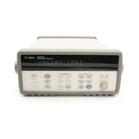
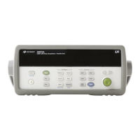
User Manuals: Keysight 34970A Data Acquisition Unit
Manuals and User Guides for Keysight 34970A Data Acquisition Unit. We have
2
Keysight 34970A Data Acquisition Unit manuals available for free PDF download: User Manual, Technical Overview
Keysight 34970A User Manual (353 pages)
Data Acquisition / Switch Unit
Brand:
Keysight
| Category:
Switch
| Size: 5 MB
Table of Contents
Software Updates/Licenses
3
Restricted Rights Legend
3
Safety Symbols
4
Safety Considerations
5
General
5
Before Applying Power
5
Ground the Instrument
5
Do Not Operate in an Explosive Atmosphere
5
Do Not Remove the Instrument Cover
6
Do Not Modify the Instrument
6
In Case of Damage
6
Regulatory Markings
7
Waste Electrical and Electronic Equipment (WEEE) Directive 2002/96/ EC
8
Product Category
8
Sales and Technical Support
8
Keysight 34970A/34972A Data Acquisition / Switch Unit
9
The Front Panel at a Glance
11
The Front-Panel Menu at a Glance
12
Display Annunciators
14
The 34970A Rear Panel at a Glance
15
The 34972A Rear Panel at a Glance
16
Benchlink Data Logger 3 at a Glance
18
The Plug-In Modules at a Glance
19
Table of Contents
23
Quick Start
33
To Prepare the Instrument for Use
34
Benchlink Data Logger Software
36
Benchlink Data Logger 3 Software Installation Procedure
36
On-Line Help System
37
To Connect Wiring to a Module
38
To Set the Time and Date
40
To Configure a Channel for Scanning
42
To Copy a Channel Configuration
45
To Close a Channel
47
If the Instrument Does Not Turn on
49
To Adjust the Carrying Handle
52
To Rack Mount the Instrument
53
Front-Panel Overview
56
Front-Panel Menu Reference
56
To Monitor a Single Channel
59
To Set a Scan Interval
60
To Apply MX+B Scaling to Measurements
61
To Configure Alarm Limits
62
To Read a Digital Input Port
64
To Write to a Digital Output Port
65
To Read the Totalizer Count
66
To Output a DC Voltage
67
To Configure the Remote Interface - 34970A
68
To Configure the Remote Interface - 34972A
71
To Store the Instrument State
74
System Overview
75
Data Acquisition System Overview
76
The Computer and Interface Cable (34970A Only)
77
Measurement Software
78
The 34970A/34972A Data Acquisition / Switch Unit
80
Plug-In Modules
81
System Cabling
83
Transducers and Sensors
84
Alarm Limits
85
Signal Routing and Switching
86
Switching Topologies
86
Measurement Input
90
The Internal DMM
90
Scanning
92
Scanning with External Instruments
94
The Multifunction Module
96
Control Output
98
The Multifunction Module
98
The Actuator / General Purpose Switch
100
Features and Functions
103
SCPI Language Conventions
103
Rules for Using a Channel List
103
Scanning
104
Rules for Scanning
104
Power Failure
107
Adding Channels to a Scan List
108
Scan Interval
110
Scan Count
117
Reading Format
118
Channel Delay
119
Automatic Channel Delays
120
Viewing Readings Stored in Memory
122
Scanning with External Instruments
125
General Measurement Configuration
129
Measurement Range
129
Measurement Resolution
131
Custom A/D Integration Time
133
Autozero
135
Temperature Measurement Configuration
136
Measurement Units
136
Thermocouple Measurements
137
RTD Measurements
139
Thermistor Measurements
141
Voltage Measurement Configuration
142
DC Input Resistance
142
AC Low Frequency Filter
143
Resistance Measurement Configuration
144
Offset Compensation
144
Current Measurement Configuration
145
AC Low Frequency Filter
145
Frequency Measurement Configuration
147
Low Frequency Timeout
147
MX+B Scaling
148
Alarm Limits
151
Viewing Stored Alarm Data
155
Using the Alarm Output Lines
157
Using Alarms with the Multifunction Module
159
Digital Input Operations
162
Totalizer Operations
164
Digital Output Operations
167
DAC Output Operations
169
System-Related Operations
170
State Storage
170
Error Conditions
172
Self-Test
173
Display Control
174
Real-Time System Clock
175
Internal DMM Disable
175
Firmware Revision Query
176
Relay Cycle Count
177
Single-Channel Monitoring
179
SCPI Language Version Query
180
Mass Memory (USB) Subsystem - 34972A
181
General Capabilities
181
SCPI Commands
183
Folder and File Structure
183
Contents of Data Files
185
USB Drive Front Panel - 34972A
187
Setting up Automatic Logging
187
Exporting Readings
187
Formatting Readings
187
Importing an Instrument Configuration
188
Remote Interface Configuration - 34970A
189
GPIB Address
189
Remote Interface Selection
190
Baud Rate Selection (RS-232)
190
Parity Selection (RS-232)
191
Flow Control Selection (RS-232)
192
Remote Interface Configuration - 34972A
194
Enabling and Disabling LAN Connectivity
194
Determining the Status of LAN Connectivity
194
Resetting the LAN
194
Enabling and Disabling DHCP
195
Setting the IP Address
195
Setting the Subnet Mask
196
Setting the Default Gateway
196
Setting the DNS Server
196
Viewing the MAC Address
197
Calibration Overview
198
Calibration Security
198
Calibration Message
201
Calibration Count
202
Factory Reset State
203
Instrument Preset State
205
Multiplexer Module Default Settings
207
Module Overview
209
34901A 20-Channel Multiplexer
210
34902A 16-Channel Multiplexer
213
34903A 20-Channel Actuator
216
34904A 4X8 Matrix Switch
219
34905A/6A Dual 4-Channel RF Multiplexers
222
34907A Multifunction Module
225
34908A 40-Channel Single-Ended Multiplexer
227
Error Messages
232
Execution Errors
233
Instrument Errors
238
Self-Test Errors
246
Calibration Errors
248
Plug-In Module Errors
251
Application Programs
254
Example Programs for Excel 7.0
255
Excel 7.0 Example: Takereadings Macro
256
Excel 7.0 Example: Port Configuration Macro
258
Excel 7.0 Example: Scanchannels Macro
260
Example Programs for C and C
263
C/C++ Example: Dac_Out.C
264
C/C++ Example: Stat_Reg.C
265
Tutorial
267
System Cabling and Connections
268
Cable Specifications
268
Grounding Techniques
270
Shielding Techniques
271
Separation of High-Level and Low-Level Signals
271
Sources of System Cabling Errors
272
Measurement Fundamentals
276
The Internal DMM
276
Temperature Measurements
278
Sources of Error in Thermocouple Measurements
286
DC Voltage Measurements
288
Sources of Error in DC Voltage Measurements
289
AC Voltage Measurements
294
Sources of Error in AC Voltage Measurements
297
Current Measurements
302
Sources of Error in DC Current Measurements
303
Sources of Error in AC Current Measurements
303
Resistance Measurements
304
Sources of Error in Resistance Measurements
307
Strain Gage Measurements
308
Frequency and Period Measurements
312
Low-Level Signal Multiplexing and Switching
314
One-Wire (Single-Ended) Multiplexers
315
Two-Wire Multiplexers
316
Four-Wire Multiplexers
317
Signal Routing and Multiplexing
318
Sources of Error in Multiplexing and Switching
319
Actuators and General-Purpose Switching
321
Snubber Circuits
322
RC Protection Networks
322
Using Varistors
323
Using Attenuators
324
Matrix Switching
325
Combining Matrices
326
RF Signal Multiplexing
327
Sources of Error in RF Switching
328
Multifunction Module
329
Digital Input
329
Digital Output
330
Using an External Pull-Up
331
Driving External Switches
332
Totalizer
333
Totalizer Errors
334
Voltage (DAC) Output
335
DAC Errors
336
Relay Life and Preventive Maintenance
337
Relay Life
338
Relay Load
338
Switching Frequency
339
Replacement Strategy
339
Specifications
341
Advertisement
Keysight 34970A Technical Overview (28 pages)
Brand:
Keysight
| Category:
Switch
| Size: 6 MB
Table of Contents
Table of Contents
2
Features
3
More Power and Flexibility than You Ever Imagined You Could Afford
6
The Keysight 34970A/34972A Offers Unequaled Versatility for Your Data Acquisition Applications
7
A Powerful, Flexible Data Acquisition System for Automated Test
10
Flexible Functionality
10
Signal Conditioning
10
ATE Feature Checklist
11
Low-Cost, High-Quality Switching for Automated Test
12
34970A and 34972A Keysight Modules-At-A-Glance Selection Guide
13
Customize Your Keysight 34970A/34972A with Plug-In Modules
13
Keysight Quality
14
Spec Interpretation Guide
15
34970A/34972A Accuracy Specifications ±(% of Reading + % of Range)[1]
16
Single Channel Reading Rates to I/O or Internal Memory
18
System Specifications
19
Modules Specifications
20
Multiplexer Selection Guide
21
34901A
21
34902A
22
34903A
23
34905A 50 Ω/34906A 75
24
34907A
25
Multifunction Module
25
Analog Output
25
Rack Mounting and Dimensions
26
Ordering Information
27
Advertisement
Related Products
Keysight 34972A
Keysight 34980A
Keysight 34907A
Keysight 34921A
Keysight 34924A
Keysight 34925A
Keysight 34922A
Keysight 34951A
Keysight 34941A
Keysight 34942A
Keysight Categories
Measuring Instruments
Test Equipment
Multimeter
Portable Generator
Power Supply
More Keysight Manuals
Login
Sign In
OR
Sign in with Facebook
Sign in with Google
Upload manual
Upload from disk
Upload from URL