Sign In
Upload
Manuals
Brands
Juniper Manuals
Switch
EX2300 Series
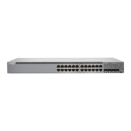
Juniper EX2300 Series Manuals
Manuals and User Guides for Juniper EX2300 Series. We have
6
Juniper EX2300 Series manuals available for free PDF download: Features Manual, Hardware Manual, Quick Start Manual, Quick Start
Juniper EX2300 Series Features Manual (476 pages)
DHCP and Other System Services Feature Guide
Brand:
Juniper
| Category:
Network Router
| Size: 4.72 MB
Table of Contents
Table of Contents
3
List of Figures
11
About the Documentation
15
Documentation and Release Notes
15
Supported Platforms
15
Using the Examples in this Manual
15
Merging a Full Example
16
Merging a Snippet
16
Documentation Conventions
17
About the Documentation
17
Table 1: Notice Icons
17
Table 2: Text and Syntax Conventions
18
Documentation Feedback
19
Requesting Technical Support
19
Self-Help Online Tools and Resources
19
Opening a Case with JTAC
20
Chapter 1 DHCP Services
21
DHCP and DHCP Relay
21
DHCP Services
23
Understanding DHCP Services for Switches
23
DHCP Client/Server Model
23
Using DHCP
24
DHCP Relay Servers and DHCP Servers
24
Figure 1: DHCP Client/Server Model
24
Legacy DHCP and Extended DHCP for Server Versions
25
DHCP Services
25
Table 3: Legacy DHCP and Extended DHCP Server Hierarchy Levels
25
Configuring DHCP on a Switch
26
How DHCP Works
26
Figure 2: DHCP Four-Step Transfer
26
Configuring DHCP Services (J-Web Procedure)
27
Configuring DHCP Services (J-Web Procedure) on EX Series Switches
27
Table 4: DHCP Service Configuration Pages Summary
28
Configuring DHCP Services on EX4300 Switches (J-Web Procedure)
30
Table 5: DHCP Service Configuration Pages Summary for EX4300 Switches
30
Configuring a Switch as a DHCP Server (CLI Procedure)
34
Configuring the Switch as a Local DHCP Server
35
Configuring a DHCP Client (CLI Procedure)
37
Configuring a DHCP SIP Server (CLI Procedure)
38
Table 6: DHCP Client Settings
38
DHCP Local Server
41
Extended DHCP Local Server Overview
42
Chapter 2 DHCP Local Server
43
Table 7: Comparing the Extended DHCP Local Server to the Traditional DHCP
43
Interaction Among the DHCP Client, Extended DHCP Local Server, and Address-Assignment Pools
44
Local Server
44
Providing DHCP Client Configuration Information
45
Table 8: Information in Authentication Grant
45
DHCP Local Server and Address-Assignment Pools
46
Minimal Configuration for Clients
46
Example: Minimum Extended DHCP Local Server Configuration
47
Overriding Default DHCP Local Server Configuration Settings
48
Deleting DHCP Local Server and DHCP Relay Override Settings
50
Configuring a Token for DHCP Local Server Authentication
51
Centrally Configured Opaque DHCP Options
52
Data Flow for RADIUS-Sourced DHCP Options
54
Figure 3: DHCP Options Data Flow
54
Multiple VSA 26-55 Instances Configuration
55
DHCP Options that Cannot be Centrally Configured
55
Port Number Requirements for DHCP Firewall Filters
56
Table 9: Unsupported Opaque DHCP Options
56
Verifying and Managing DHCP Local Server Configuration
57
Chapter 3 Dhcpv6 Local Server
59
Dhcpv6 Local Server Overview
60
Table 10: RADIUS Attributes and Vsas for Dhcpv6 Local Server
60
Enabling Dhcpv6 Rapid Commit Support
61
Specifying the Delegated Address Pool for Ipv6 Prefix Assignment
62
Preventing Binding of Clients that Do Not Support Reconfigure Messages
62
Verifying and Managing Dhcpv6 Local Server Configuration
63
Chapter 4 DHCP Relay Agent
65
Extended DHCP Relay Agent Overview
66
Interaction Among the DHCP Relay Agent, DHCP Client, and DHCP
67
Servers
67
DHCP Liveness Detection
68
Configuring an Extended DHCP Relay Server on EX Series Switches (CLI Procedure)
69
Example: Minimum DHCP Relay Agent Configuration
70
DHCP Relay Proxy Overview
71
Interaction Among DHCP Relay Proxy, DHCP Client, and DHCP Servers
71
Enabling DHCP Relay Proxy Mode
72
Example: Configuring DHCP Relay Agent Selective Traffic Processing Based on DHCP Option Strings
73
Using Layer 2 Unicast Transmission for DHCP Packets
78
Sending Release Messages When Clients Are Deleted
78
Disabling Automatic Binding of Stray DHCP Requests
79
Using DHCP Relay Agent Option 82 Information
80
Configuring Option 82 Information
81
Including a Prefix in DHCP Options
83
Including a Textual Description in DHCP Options
85
DHCP Relay Agent
85
Trusting Option 82 Information
87
Overriding the Default DHCP Relay Configuration Settings
88
Overriding Option 82 Information
91
Agent
92
Replacing the DHCP Relay Request and Release Packet Source Address
92
Configuring DHCP Snooped Packets Forwarding Support for DHCP Relay
93
Agent
97
Table 11: Actions for DHCP Relay Agent Snooped Packets When DHCP Snooping
98
Table 12: Actions for DHCP Relay Agent Snooped Packets When DHCP Snooping
98
Table 13: Actions for Snooped BOOTREPLY Packets
98
Configuring Named Server Groups
99
Configuring Active Server Groups to Apply a Common DHCP Relay Agent Configuration to Named Server Groups
100
Disabling DHCP Relay
100
Verifying and Managing DHCP Relay Configuration
101
By Default
102
Chapter 5 Dhcpv6 Relay Agent
105
Inserting Dhcpv6 Interface-ID Option (Option 18) in Dhcpv6 Packets
106
Verifying and Managing Dhcpv6 Relay Configuration
107
Chapter 6 Configuring Groups of DHCP Interfaces
109
Guidelines for Configuring Interface Ranges for Groups of DHCP Interfaces
110
Configuring Group-Specific DHCP Local Server Options
111
Configuring Group-Specific DHCP Relay Options
112
Chapter 7 DHCP Liveness Detection
115
Configuring Detection of DHCP Local Server Client Connectivity
116
Connectivity
118
Chapter 8 Managing DHCP Clients
121
Configuring Passwords for Usernames
122
Creating Unique Usernames for DHCP Clients
123
Specifying the Maximum Number of DHCP Clients Per Interface
126
DHCP Local Server Handling of Client Information Request Messages
127
Enabling Processing of Client Information Requests
128
Chapter 9 Forcing Dynamic Reconfiguration of Clients from a DHCP Local Server
131
Dynamic Client/Server Interaction for Dhcpv4
132
Process
133
Table 14: Action Taken for Events that Occur During a Reconfiguration
133
Clients
134
Requesting DHCP Local Server to Initiate Reconfiguration of Client Bindings
136
Configuring Dynamic Reconfiguration Attempts for DHCP Clients
137
Configuring Deletion of the Client When Dynamic Reconfiguration Fails
138
Disconnect
139
Chapter 10 Managing IP Address Assignment
141
Address-Assignment Pool to Use
142
Matching
143
DHCP Auto Logout Overview
144
How DHCP Identifies and Releases Clients
145
Table 15: DHCP Relay Agent Option 82 Value for Auto Logout
146
Option 60 and Option 82 Requirements
146
Automatically Logging out DHCP Clients
147
IA_NA Option
148
Multiple Address Assignment for Dhcpv6 Clients
149
Part 2 Other System Services
151
Chapter 11 Configuring Packet Forwarding Options
153
Part 3 Configuration Statements and Operational Commands
155
Chapter 12 Configuration Statements (DHCP and DHCP Relay)
157
Access (Dynamic Access Routes)
161
Access-Internal (Dynamic Access-Internal Routes)
162
Active-Server-Group
164
Allow-No-End-Option (DHCP Relay Agent)
165
Allow-Snooped-Clients
166
Always-Write-Giaddr
167
Always-Write-Option-82
168
Attempts (DHCP Local Server)
169
Authentication (DHCP Local Server)
170
Authentication (DHCP Relay Agent)
171
Circuit-ID (DHCP Relay Agent)
173
Circuit-Type (DHCP Local Server)
176
Circuit-Type (DHCP Relay Agent)
177
Clear-On-Abort (DHCP Local Server)
178
Client-Discover-Match (DHCP Local Server)
179
Client-ID (DHCP Local Server)
180
Client-ID (DHCP Relay Agent)
181
Delegated-Pool (DHCP Local Server)
182
Delimiter (DHCP Local Server)
183
Delimiter (DHCP Relay Agent)
185
Detection-Time
186
Dhcp (DHCP Client)
187
Dhcp-Local-Server
188
Dhcp-Relay
194
Dhcpv6 (DHCP Local Server)
203
Dhcpv6 (DHCP Relay Agent)
207
Disable-Relay
213
Domain-Name (DHCP Local Server)
214
Domain-Name (DHCP Relay Agent)
216
Domain-Search
217
Drop (DHCP Relay Agent Option)
218
Dynamic-Profile (DHCP Local Server)
219
Dynamic-Profile (DHCP Relay Agent)
220
External-Authority
221
Failure-Action
222
Forward-Snooped-Clients (DHCP Local Server)
223
Forward-Snooped-Clients (DHCP Relay Agent)
224
Group (DHCP Local Server)
225
Group (DHCP Relay Agent)
228
Holddown-Interval
231
Include-Irb-And-L2
232
Interface (DHCP Local Server)
234
Interface (DHCP Relay Agent)
236
Interface-Client-Limit (DHCP Local Server)
238
Interface-Client-Limit (DHCP Relay Agent)
240
Interface-Delete (Subscriber Management or DHCP Client Management)
241
Interface-Name (DHCP Local Server)
242
Interface-Name (DHCP Relay Agent)
243
Ip-Address-First
244
Layer2-Unicast-Replies
245
Lease-Time
246
Liveness-Detection
247
Local-Server-Group (DHCP Relay Agent Option)
248
Mac-Address (DHCP Local Server)
249
Mac-Address (DHCP Relay Agent)
250
Maximum-Hop-Count
251
Maximum-Lease-Time (DHCP)
252
Method
253
Minimum-Interval
254
Minimum-Receive-Interval
255
Minimum-Wait-Time
256
Multiplier
257
Name-Server
258
Next-Hop (Dynamic Access-Internal Routes)
259
No-Adaptation
260
No-Allow-Snooped-Clients
261
No-Bind-On-Request (DHCP Relay Agent)
262
No-Listen
263
No-Vlan-Interface-Name
264
Option-60 (DHCP Local Server)
266
Option-60 (DHCP Relay Agent)
267
Option-82 (DHCP Local Server Authentication)
268
Option-82 (DHCP Local Server Pool Matching)
269
Option-82 (DHCP Relay Agent)
270
Option-Number (DHCP Relay Agent Option)
271
Overrides (DHCP Local Server)
272
Overrides (DHCP Relay Agent)
274
Password (DHCP Local Server)
276
Password (DHCP Relay Agent)
278
Pool (DHCP Local Server Overrides)
279
Pool-Match-Order
280
Preference (Subscriber Management)
281
Prefix (DHCP Relay Agent)
282
Process-Inform
283
Proxy-Mode
285
Radius-Disconnect (DHCP Local Server)
286
Rapid-Commit (Dhcpv6 Local Server)
287
Reconfigure (DHCP Local Server)
288
Relay-Agent-Interface-ID (DHCP Local Server)
289
Relay-Agent-Interface-ID (Dhcpv6 Relay Agent)
290
Relay-Agent-Remote-ID (DHCP Local Server)
291
Relay-Agent-Remote-ID (Dhcpv6 Relay Agent Username)
292
Relay-Option (DHCP Relay Agent)
293
Relay-Option-82
294
Relay-Server-Group (DHCP Relay Agent Option)
295
Replace-Ip-Source-With
296
Retransmission-Attempt
297
Retransmission-Interval
298
Route-Suppression (DHCP Local Server and Relay Agent)
299
Routing-Instance-Name (DHCP Local Server)
300
Routing-Instance-Name (DHCP Relay Agent)
302
Send-Release-On-Delete (DHCP Relay Agent)
304
Server (DNS, Port, and TFTP Service)
305
Server-Address
306
Server-Group
307
Server-Identifier
308
Service-Profile (DHCP Local Server)
309
Service-Profile (DHCP Relay Agent)
310
Session-Mode
311
Sip-Server
312
Source-Address-Giaddr
313
Static-Binding
314
Strict (DHCP Local Server)
315
Threshold (Detection-Time)
316
Threshold (Transmit-Interval)
317
Timeout (DHCP Local Server)
318
Token (DHCP Local Server)
319
Trace (DHCP Relay Agent)
320
Traceoptions (DHCP Server)
321
Traceoptions (DNS, Port, and TFTP Packet Forwarding)
324
Transmit-Interval
326
Trigger (DHCP Local Server)
327
Trust-Option-82
328
Use-Interface-Description
329
Use-Primary (DHCP Local Server)
331
Use-Primary (DHCP Relay Agent)
332
Use-Vlan-ID
334
User-Prefix (DHCP Local Server)
336
Username-Include (DHCP Local Server)
338
Username-Include (DHCP Relay Agent)
340
Version (BFD)
342
Wins-Server (System)
343
Chapter 13 Configuration Statements (Forwarding Options)
345
Description (Forwarding Options)
346
Helpers
347
Interface (DNS, Port, and TFTP Packet Forwarding or Relay Agent)
350
No-Listen
351
Port (Packet Forwarding)
352
Server (DNS, Port, and TFTP Service)
354
Traceoptions (DNS, Port, and TFTP Packet Forwarding)
355
Chapter 14 Operational Commands (DHCP and DHCP Relay)
357
Clear Dhcp Relay Binding
359
Clear Dhcp Server Binding
362
Clear Dhcp Relay Statistics
365
Table 16: Clear Dhcp Relay Statistics Output Fields
366
Clear Dhcp Server Statistics
368
Clear Dhcpv6 Relay Binding
370
Clear Dhcpv6 Server Binding
373
Clear Dhcpv6 Relay Statistics
376
Clear Dhcpv6 Server Statistics
378
Clear System Services Dhcp Binding
379
Clear System Services Dhcp Conflict
380
Clear System Services Dhcp Statistics
381
Request Dhcp Server Reconfigure
382
Request Dhcpv6 Server Reconfigure
384
Request System Reboot
386
Show Dhcp Relay Binding
392
Table 17: Show Dhcp Relay Binding Output Fields
393
Show Dhcp Server Binding
398
Table 18: Show Dhcp Server Binding Output Fields
399
Show Dhcp Relay Statistics
405
Table 19: Show Dhcp Relay Statistics Output Fields
406
Show Dhcp Server Statistics
409
Table 20: Show Dhcp Server Statistics Output Fields
410
Show Dhcpv6 Relay Binding
413
Table 21: Show Dhcpv6 Relay Binding Output Fields
414
Show Dhcpv6 Server Binding
421
Table 22: Show Dhcpv6 Server Binding Output Fields
422
Show Dhcpv6 Relay Statistics
427
Table 23: Show Dhcpv6 Relay Statistics Output Fields
428
Show Dhcpv6 Server Statistics
431
Table 24: Show Dhcpv6 Server Statistics Output Fields
432
Table 25: Show Route Extensive Output Fields
434
Show Route Protocol
452
Table 26: Show System Services Dhcp Binding Output Fields
465
Table 27: Show System Services Dhcp Conflict Output Fields
468
Table 28: Show System Services Dhcp Global Output Fields
469
Table 29: Show System Services Dhcp Pool Output Fields
471
Table 30: Show System Services Dhcp Statistics Output Fields
474
Advertisement
Juniper EX2300 Series Hardware Manual (294 pages)
Brand:
Juniper
| Category:
Switch
| Size: 4.68 MB
Table of Contents
Table of Contents
3
About the Documentation
17
Documentation and Release Notes
17
Supported Platforms
17
Documentation Conventions
17
Table 1: Notice Icons
18
Table 2: Text and Syntax Conventions
18
Documentation Feedback
19
About the Documentation
19
Requesting Technical Support
20
Self-Help Online Tools and Resources
20
Opening a Case with JTAC
20
Overview
23
Chassis Components and Descriptions
23
Chapter 1 System Overview
25
System Overview
25
EX2300 Switches Hardware Overview
25
EX2300 Switches First View
25
Cable Guard
26
Console Ports
26
Uplink Ports
26
Front Panel of an EX2300 Switch
27
Power over Ethernet (Poe) Ports
27
Security Slot
27
System Overview
27
Figure 1: Front Panel of an EX2300-C Switch with 12 Gigabit Ethernet Ports with
28
Figure 2: Front Panel of an EX2300-C Switch with 12 Gigabit Ethernet Ports
28
Figure 3: Front Panel of an EX2300 Switch with 24 Gigabit Ethernet Ports with
29
System Overview
29
Figure 4: Front Panel of an EX2300 Switch with 48 Gigabit Ethernet Ports with
30
Figure 5: Rear Panel of an EX2300-C Switch with 12 Gigabit Ethernet Ports with
30
Rear Panel of an EX2300 Switch
30
Figure 6: Rear Panel of an EX2300-C Switch with 12 Gigabit Ethernet Ports Without Poe Capability
31
Figure 7: Rear Panel of an AC-Powered EX2300 Switch with 24 Gigabit Ethernet Ports with Poe Capability
32
Figure 8: Rear Panel of an AC-Powered EX2300 Switch with 24 Gigabit Ethernet Ports Without Poe Capability
32
Figure 9: Rear Panel of a DC-Powered EX2300 Switch with 24 Gigabit Ethernet
32
EX2300 Switch Models
33
Figure 10: Rear Panel of an AC-Powered EX2300 Switch with 48 Gigabit Ethernet Ports with Poe Capability
33
Figure 11: Rear Panel of an AC-Powered EX2300 Switch with 48 Gigabit Ethernet Ports Without Poe Capability
33
EX2300 Switch Hardware and CLI Terminology Mapping
34
Table 3: EX2300 Switch Models
34
Table 4: CLI Equivalents of Terms Used in Documentation for EX2300
34
Chapter 2 Chassis Components and Descriptions
37
Chassis Physical Specifications for EX2300 Switches
37
Table 5: Physical Specifications of the EX2300 Switch Chassis
37
Chassis Status Leds in EX2300 Switches
38
Figure 12: Chassis Status Leds in EX2300-C Switches
38
Figure 13: Chassis Status Leds in EX2300 Switches Except the EX2300-C
38
Table 6: Chassis Status Leds in an EX2300 Switch
38
Management Port Leds in EX2300 Switches
40
Figure 14: Leds on the Management Port on EX2300-C Switches
40
Figure 15: Leds on the Management Port on EX2300 Switches
40
Table 7: Link/Activity LED on the Management Port on EX2300 Switches
40
RJ-45 Network Port Leds and Uplink Port Leds in EX2300 Switches
41
Figure 16: Leds on RJ-45 Network Ports
41
Figure 17: Leds on the Uplink Ports in EX2300-C Switches
41
Figure 18: Leds on the Uplink Ports in an EX2300 Switches Except the EX2300-C
41
Table 8: Status LED on the Management Port on EX2300 Switches
41
Figure 19: Port Mode Leds on EX2300 Switches
42
Table 9: Link/Activity LED on the RJ-45 Network Ports and the Uplink Ports in
42
Table 10: Status LED on the RJ-45 Network Ports in EX2300 Switches
42
Table
42
Table 11: Status LED on the Uplink Ports in EX2300 Switches
43
Chapter 3 Cooling System and Airflow
45
Cooling System and Airflow in an EX2300 Switch
45
Airflow Direction in EX2300 Switches with 24 Ports with Poe Capability
45
Airflow Direction in EX2300 Switches with 48 Ports with Poe Capability
46
Figure 20: Airflow Direction in EX2300 Switches with 24 Ports with Poe
46
Airflow Direction in EX2300 Switches Without Poe Capability
47
Capability
48
Chapter 4 Power Supplies
49
Power Supplies
49
Power Supply in EX2300 Switches
49
Table 12: Power Consumed by EX2300 Switches
49
Chapter 5 Viewing System Information
51
Dashboard for EX Series Switches
51
Graphical Chassis Viewer
52
Table 13: Details of a Virtual Chassis Member Switch
52
System Information Panel
53
Table 14: Status of a Member Switch in a Virtual Chassis
53
Table 15: System Information
53
Health Status Panel
55
Table 16: Health Status
55
Capacity Utilization Panel
57
Alarms Panel
57
Table 17: Capacity Utilization
57
File System Usage
58
Chassis Viewer
58
Table 18: Chassis Viewer for EX2200 Switches
58
Table 19: Chassis Viewer for EX2200-C Switches
59
Table 20: Chassis Viewer for EX3200, EX3300, and EX4200 Switches
59
Table 21: Chassis Viewer for EX4300 Switches
61
Table 22: Chassis Viewer for EX4500 Switches
62
Table 23: Chassis Viewer for EX4550 Switches
63
Table 24: Chassis Viewer for EX4600 Switches
65
Table 25: Chassis Viewer for EX6210 Switches
65
Table 26: Chassis Viewer for EX8208 Switches
66
Table 27: Chassis Viewer for EX8216 Switches
68
Table 28: Chassis Viewer for XRE200 External Routing Engines
68
Part 2 Site Planning, Preparation, and Specifications
71
Chapter 6 Preparation Overview
73
Environmental Requirements and Specifications for EX Series Switches
75
Table 30: EX Series Switch Environmental Tolerances
75
General Site Guidelines
79
Site Electrical Wiring Guidelines
79
Table 31: Site Electrical Wiring Guidelines
79
Chassis Physical Specifications for EX2300 Switches
80
Table 32: Physical Specifications of the EX2300 Switch Chassis
80
Rack Requirements
81
Table 33: Rack Requirements and Specifications
81
Requirements for Mounting an EX2300 Switch on or under a Desk or Other Level Surface or on a Wall
82
Cabinet Requirements
82
Table 34: Cabinet Requirements and Specifications
82
Clearance Requirements for Airflow and Hardware Maintenance for EX2300
83
Switches
83
Figure 23: Clearance Requirements for Airflow and Hardware Maintenance for
84
Figure 24: Clearance Requirements for Airflow and Hardware Maintenance for EX2300 Switches Except EX2200-C Switches
84
Figure 25: Airflow Direction in EX2300 Switches with 24 Ports with Poe
85
Capability
85
Figure 26: Airflow Direction in EX2300 Switches with 48 Ports with Poe
86
Figure 27: Airflow Direction in EX2300 Switches Without Poe Capability
86
Preparation Overview
73
Site Preparation Checklist for EX2300 Switches
73
Table 29: Site Preparation Checklist
73
Chapter 7 Power Specifications and Requirements
89
Power Specifications for EX2300 Switches
89
Table 35: AC Power Supply Electrical Specifications for EX2300 Switches
89
AC Power Cord Specifications for EX2300 Switches
90
Table 36: DC Power Supply Electrical Specifications for EX2300 Switches
90
Figure 28: AC Plug Types
91
Table 37: AC Power Cord Specifications
91
Calculating the EX Series Switch Fiber-Optic Cable Power Budget
92
Calculating the EX Series Switch Fiber-Optic Cable Power Margin
92
Table 38: Estimated Values for Factors Causing Link Loss
93
Chapter 8 Transceiver and Cable Specifications
95
Pluggable Transceivers Supported on EX2300 Switches
95
Table 39: Optical Interface Support and Copper Interface Support for SFP
97
Table 40: Optical Interface Support for SFP+ Transceivers in EX2300
116
Pluggable Transceivers Supported on EX Series Switches
119
SFP+ Direct Attach Copper Cables for EX Series Switches
121
Cable Specifications
121
Figure 29: SFP+ Direct Attach Copper Cables for EX Series Switches
121
Table 41: Software Support for SFP+ Passive Direct Attach Copper Cables for
121
Table 42: SFP+ Direct Attach Copper Cable Specifications
124
Standards Supported by These Cables
127
Management Cable Specifications
127
Understanding EX Series Switches Fiber-Optic Cable Signal Loss, Attenuation
128
And Dispersion
128
Signal Loss in Multimode and Single-Mode Fiber-Optic Cable
128
Table 43: Specifications of Cables to Connect to Management Devices
128
Attenuation and Dispersion in Fiber-Optic Cable
129
Chapter 9 Pinout Specifications
131
USB Port Specifications for an EX Series Switch
132
Mini-USB Port Pinout Specifications
133
Table 45: Mini-USB Type-B Console Port Pinout Information
133
RJ-45 Management Port Connector Pinout Information
134
Port, QSFP+ Port, SFP+ Port, and SFP Port Connector Pinout Information
134
Table 46: RJ-45 Management Port Connector Pinout Information
134
Table 47: 10/100/1000BASE-T Ethernet Network Port Connector Pinout
134
Table 48: SFP Network Port Connector Pinout Information
135
Table 49: SFP+ Network Port Connector Pinout Information
136
Table 50: QSFP+ Network Port Connector Pinout Information
137
SFP+ Uplink Port Connector Pinout Information for an EX2300 Switch
139
Table 51: Connector Pinout Information for the 10-Gigabit Ethernet Uplink
139
RJ-45 to DB-9 Serial Port Adapter Pinout Information
140
Table 52: RJ-45 to DB-9 Serial Port Adapter Pinout Information
140
Pinout Specifications
131
Console Port Connector Pinout Information
131
Table 44: Console Port Connector Pinout Information
131
Chapter 10 Planning the Virtual Chassis
141
Planning EX2300 Virtual Chassis
141
Understanding EX2300 Virtual Chassis Hardware Configuration
142
Part 3 Initial Installation and Configuration
143
Chapter 11 Unpacking the Switch
145
Parts Inventory (Packing List) for an EX2300 Switch
146
Table 53: Parts List for EX2300 Switches
146
Registering Products-Mandatory for Validating Slas
147
Unpacking the Switch
145
Unpacking an EX2300 Switch
145
Chapter 12 Installing the Switch
149
Installing and Connecting an EX2300 Switch
149
Mounting an EX2300 Switch
150
Table 54: EX2300 Switch Mounting Methods
150
Mounting an EX2300 Switch on a Desk or Other Level Surface
151
Figure 30: Attaching a Cable Guard to an EX2300-C Switch
152
Figure 31: Securing the EX2300-C Switch by Using the Security Slot
153
Screws
153
Figure 32: Attaching a Cable Guard to an EX2300-C Switch
154
Figure 33: Measurements for Installing Mounting Screws for Mounting EX2300-C Switches under a Desk or Other Level Surface by Using Screws
155
Figure 34: Mounting the EX2300-C Switch under a Desk or Other Level Surface
156
Figure 35: Securing the EX2300-C Switch by Using the Security Slot
156
Mounting an EX2300 Switch on Two Posts of a Rack or Cabinet
157
Figure 36: Attaching the Mounting Bracket Along the Front of the Switch
158
Mounting an EX2300 Switch on Four Posts of a Rack or Cabinet
159
Figure 37: Mounting the Switch on Two Posts of a Rack
159
Figure 38: Attaching the Front-Mounting Bracket to the Side Mounting-Rail
161
Figure 39: Attaching the Side Mounting-Rail to the Switch Chassis
161
Figure 40: Mounting the Switch to the Front Posts of a Rack
162
Figure 41: Sliding the Rear Mounting-Blades into the Side Mounting-Rail
162
Mounting an EX2300 Switch on a Wall
163
Mounting an EX2300-C Switch on a Wall
163
Figure 42: Attaching a Cable Guard to an EX2300-C Switch
164
Figure 43: Measurements for Installing Mounting Screws for Mounting an
165
Mounting an EX2300 Switch Except the EX2300-C Switch on a Wall
166
Figure 44: Mounting an EX2300-C Switch on a Wall
166
Figure 45: Securing the EX2300-C Switch by Using the Security Slot
166
Figure 46: Attaching Wall-Mount Brackets to an EX2300 Switch Except the
168
Figure 47: Measurements for Installing Mounting Screws to Mount an EX2300
170
Material
171
Figure 48: Mounting an EX2300 Switch on a Wall
171
Figure 49: Attaching a Cable Guard to an EX2300-C Switch
172
Figure 50: Attaching Rubber Pads to an EX2300-C Switch
173
Figure 51: Attaching the Magnet Mount Sheet to an EX2300-C Switch
173
Figure 52: Mounting an EX2300-C Switch on or under a Surface Made of Ferrous
174
Figure 53: Securing the EX2300-C Switch by Using the Security Slot
174
Material
174
Mounting an EX2300 Switch in a Recessed Position in a Rack or Cabinet
175
Chapter 13 Connecting the Switch to Power
177
Connecting Earth Ground to an EX Series Switch
177
Parts and Tools Required for Connecting an EX Series Switch to Earth Ground
177
Table 55: Parts and Tools Required for Connecting an EX Series Switch to Earth Ground
178
Special Instructions to Follow before Connecting Earth Ground to a
179
Connecting Earth Ground to an EX Series Switch
182
Figure 55: Connecting a Grounding Cable to an EX Series Switch
182
Chapter 14 Switch
180
Figure 54: Connecting the Grounding Lug to a Switch Mounted on Four Posts of
181
Connecting AC Power to an EX2300 Switch
183
Figure 56: Connecting an AC Power Cord Retainer Clip to the AC Power Cord Inlet on EX2300-C Switches
184
Figure 57: Connecting an AC Power Cord Retainer Clip to the AC Power Cord Inlet on EX2300 Switches Except EX2300-C Switches
184
Connecting DC Power to an EX2300 Switch
185
Figure 58: Connecting an AC Power Cord to the AC Power Cord Inlet on EX2300-C
185
Figure 59: Connecting an AC Power Cord to the AC Power Cord Inlet on EX2300 Switches Except EX2300-C Switches
185
Figure 60: Securing the Ring Lugs on the Power Cables to the Terminals on the
187
Connecting the Switch to the Network
189
Connecting a Device to a Network for Out-Of-Band Management
189
Connecting a Device to a Management Console by Using an
189
Figure 61: RJ-45 Connector on an Ethernet Cable
189
Connector
190
Figure 62: Connecting a Device to a Network for Out-Of-Band Management
190
Figure 63: RJ-45 Connector on an Ethernet Cable
190
Connecting an EX2300 Switch to a Management Console by Using Mini-USB Type-B Console Port
191
Figure 64: Connecting a Device to a Management Console through a Console
191
Figure 65: Connecting a Device Directly to a Management Console
191
Connecting a Fiber-Optic Cable
192
Figure 66: Connecting a Fiber-Optic Cable to an Optical Transceiver Installed
193
In a Device:
193
Chapter 15 Performing Initial Configuration
195
EX2300 Switch Default Configuration
195
Connecting and Configuring an EX Series Switch (CLI Procedure)
201
Connecting and Configuring an EX Series Switch (J-Web Procedure)
204
Figure 67: LCD Panel in an EX3200, EX4200, EX4500, EX4550, or EX8200
206
Figure 68: LCD Panel in an EX4300 Switch
206
Reverting to the Default Factory Configuration for the EX Series Switch
208
Reverting to the Factory-Default Configuration by Using the LCD Panel
209
Reverting to the Factory-Default Configuration by Using the Request System Zeroize Command
210
Figure 69: EX Series Switch LCD Panel
210
Reverting to the Factory-Default Configuration by Using the Load Factory-Default Command
211
Reverting to the Factory-Default Configuration by Using the Factory Reset/Mode Button on EX2300 and EX3400 Switches
212
Installing, Maintaining, and Replacing Components
213
Chapter 16 Replacing Transceiver
215
Removing a Transceiver
217
Figure 70: Installing a Transceiver
217
Figure 71: Removing an SFP, SFP+, XFP, or a QSFP+ Transceiver
219
Replacing Transceiver
215
Installing a Transceiver
215
Chapter 17 Maintaining and Replacing Fiber-Optic Cable
221
Disconnecting a Fiber-Optic Cable from a Device
222
Figure 72: Connecting a Fiber-Optic Cable to an Optical Transceiver Installed in
222
Maintaining Fiber-Optic Cables
223
Maintaining and Replacing Fiber-Optic Cable
221
Connecting a Fiber-Optic Cable
221
Chapter 18 Contactingcustomersupportandreturningthechassisor
225
Components
225
Returning an EX2300 Switch or Component for Repair or Replacement
225
Locating the Serial Number on an EX2300 Switch or Component
225
Listing the Switch and Components Details with the CLI
226
Locating the Chassis Serial Number ID Label on an EX2300 Switch
227
Contacting Customer Support to Obtain Return Material Authorization
227
Packing an EX2300 Switch or Component for Shipping
228
Packing a Switch for Shipping
229
Packing Switch Components for Shipping
229
Part 5 Troubleshooting
231
Troubleshooting
231
Chapter 19 Alarms and System Log Messages
233
Understanding Alarm Types and Severity Levels on EX Series Switches
233
Table 57: Alarm Terms
233
Chassis Component Alarm Conditions on EX2300 Switches
234
Table 58: Alarm Conditions on EX2300 Switches
235
Checking Active Alarms with the J-Web Interface
236
Monitoring System Log Messages
237
Table 59: Summary of Key Alarm Output Fields
237
Table 60: Filtering System Log Messages
238
Table 61: Viewing System Log Messages
240
Safety and Compliance Information
243
Chapter 20 General Safety Guidelines and Warnings
245
Definitions of Safety Warning Levels
246
Qualified Personnel Warning
248
Warning Statement for Norway and Sweden
249
Chapter 21 Fire Safety Requirements
251
Chapter 22 Installation Safety Guidelines and Warnings
253
Installation Instructions Warning
253
Chassis Lifting Guidelines
254
Restricted Access Warning
254
Ramp Warning
256
Rack-Mounting and Cabinet-Mounting Warnings
256
Wall-Mounting Warnings for EX2300 Switches
260
Grounded Equipment Warning
260
Chapter 23 Radiation and Laser Safety Guidelines and Warnings
263
Laser and LED Safety Guidelines and Warnings
263
General Laser Safety Guidelines
263
Class 1 Laser Product Warning
264
Class 1 LED Product Warning
264
Laser Beam Warning
264
Radiation from Open Port Apertures Warning
265
Chapter 24 Maintenance and Operational Safety Warnings
267
Maintenance and Operational Safety Guidelines and Warnings
267
Battery Handling Warning
267
Jewelry Removal Warning
268
Lightning Activity Warning
269
Operating Temperature Warning
270
Product Disposal Warning
271
Chapter 25 Electrical Safety Guidelines and Warnings
273
General Electrical Safety Guidelines and Warnings
273
Action to Take after an Electrical Accident
274
Prevention of Electrostatic Discharge Damage
275
AC Power Electrical Safety Guidelines
276
AC Power Disconnection Warning
277
DC Power Electrical Safety Guidelines for Switches
278
DC Power Disconnection Warning
281
DC Power Grounding Requirements and Warning
282
DC Power Wiring Sequence Warning
283
DC Power Wiring Terminations Warning
285
Multiple Power Supplies Disconnection Warning
286
TN Power Warning
286
Chapter 26 Agency Approvals and Compliance Statements
289
Agency Approvals for EX Series Switches
289
Compliance Statements for EMC Requirements for EX Series Switches
290
Canada
290
European Community
291
Israel
291
Japan
291
Korea
292
United States
292
Nonregulatory Environmental Standards
293
Compliance Statements for Acoustic Noise for EX Series Switches
294
Juniper EX2300 Series Hardware Manual (314 pages)
Brand:
Juniper
| Category:
Switch
| Size: 4.95 MB
Table of Contents
Table of Contents
3
About this Guide
9
Overview
10
EX2300 System Overview
11
EX2300 Switches Hardware Overview
11
EX2300 Switch Models
24
EX2300 Switch Hardware and CLI Terminology Mapping
27
Chassis Physical Specifications for EX2300 Switches
32
EX2300 Chassis
34
Chassis Status Leds in EX2300 Switches
35
Management Port Leds in EX2300 Switches
39
RJ-45 Network Port Leds and Uplink Port Leds in EX2300 Switches
43
EX2300 Cooling System
49
EX2300 Power System
55
Power Supply in EX2300 Switches
55
Power Specifications for EX2300 Switches
56
AC Power Cord Specifications for EX2300 Switches
58
Site Planning, Preparation, and Specifications
61
Site Preparation Checklist for EX2300 Switches
62
EX2300 Site Guidelines and Requirements
64
Environmental Requirements and Specifications for EX Series Switches
64
General Site Guidelines
71
Site Electrical Wiring Guidelines
71
Rack Requirements
72
Cabinet Requirements
74
Requirements for Mounting an EX2300 Switch on or under a Desk or Other Level Surface or on a Wall
75
Clearance Requirements for Airflow and Hardware Maintenance for EX2300 Switches
76
EX2300 Network Cable and Transceiver Planning
84
Pluggable Transceivers Supported on EX2300 Switches
84
SFP+ Direct Attach Copper Cables for EX Series Switches
86
Understanding EX Series Switches Fiber-Optic Cable Signal Loss, Attenuation, and Dispersion
88
Calculating the Fiber-Optic Cable Power Budget for EX Series Devices
90
Calculating the Fiber-Optic Cable Power Margin for EX Series Devices
90
EX2300 Management Cable Specifications and Pinouts
92
Management Cable Specifications
93
Console Port Connector Pinout Information
93
USB Port Specifications for an EX Series Switch
94
Mini-USB Port Pinout Specifications
95
RJ-45 Management Port Connector Pinout Information
96
Port, SFP Port, SFP+ Port, QSFP+ Port, and QSFP28 Port Connector Pinout Information
96
SFP+ Uplink Port Connector Pinout Information for an EX2300 Switch
103
RJ-45 Management Port Connector Pinout Information
105
RJ-45 to DB-9 Serial Port Adapter Pinout Information
105
EX2300 Virtual Chassis
106
Planning EX2300 Virtual Chassis
107
Understanding EX2300 Virtual Chassis Hardware Configuration
107
Initial Installation and Configuration
109
Unpacking and Mounting the EX2300 Switch
110
Unpacking an EX2300 Switch
110
Parts Inventory (Packing List) for an EX2300 Switch
111
Register Products-Mandatory to Validate Slas
112
Installing and Connecting an EX2300 Switch
113
Mounting an EX2300 Switch
114
Mounting an EX2300 Switch on a Desk or Other Level Surface
115
Mounting an EX2300-C Switch under a Desk or Other Level Surface by Using Screws
117
Mounting an EX2300 Switch on Two Posts of a Rack or Cabinet
122
Mounting an EX2300 Switch on Four Posts of a Rack or Cabinet
125
Mounting an EX2300 Switch on a Wall
128
Mounting an EX2300-C Switch on a Wall
128
Mounting an EX2300 Switch Except the EX2300-C Switch and the EX2300-24MP and EX2300-48MP Models on a Wall
133
Mounting an EX2300-C Switch on or under a Surface Made of Ferrous Material
136
Mounting an EX2300 Switch in a Recessed Position in a Rack or Cabinet
141
Connecting the EX2300 to Power
141
Connect Earth Ground to an EX Series Switch
141
Connecting AC Power to an EX2300 Switch
150
Connecting DC Power to an EX2300 Switch
153
Connecting the EX2300 to External Devices
156
Connect a Device to a Network for Out-Of-Band Management
156
Connect a Device to a Management Console Using an RJ-45 Connector
157
Connect an EX Series Switch to a Management Console Using the Mini-USB Type-B Console Port
158
Connecting the EX2300 to the Network
160
Install a Transceiver
160
Connect a Fiber-Optic Cable
163
Configuring Junos os on the EX2300
164
EX2300 Switch Default Configuration
165
Connecting and Configuring an EX Series Switch (CLI Procedure)
180
Connecting and Configuring an EX Series Switch (J-Web Procedure)
184
Reverting to the Default Factory Configuration for the EX Series Switch
188
Reverting to the EX Series Switch Factory-Default Configuration Using the Request System Zeroize Command
189
Reverting to the EX Series Switch Factory-Default Configuration Using the Load Factory-Default Command
189
Reverting to the Factory-Default Configuration Using the EX Series Switch LCD Panel
191
Reverting to the Factory-Default Configuration Using the Factory Reset/Mode Button on EX2300, EX3400, and EX4300-48MP Switches
191
Dashboard for EX Series Switches
193
Field Description
207
Front View
207
Interface Status
207
Rear View
207
Management (Me0) Port
207
Console Port
207
USB Port
207
In the Image, the Following Colors Denote the Interface Status
207
Green-Interface Is up and Operational
207
Yellow-Interface Is up but Is Nonoperational
210
Gray-Interface Is down and Nonoperational
210
Indicates the USB Port for the Switch
211
Networks for Your EX Series Switch
217
Maintaining Components
225
Maintain Transceivers
226
Remove a Transceiver
226
Remove a QSFP28 Transceiver
228
Install a Transceiver
230
Install a QSFP28 Transceiver
233
Maintain Fiber-Optic Cables
235
Connect a Fiber-Optic Cable
235
Disconnect a Fiber-Optic Cable
236
How to Handle Fiber-Optic Cables
237
Troubleshooting Hardware
239
Troubleshooting EX2300 Components
240
Understand Alarm Types and Severity Levels on EX Series Switches
240
Chassis Component Alarm Conditions on EX2300 Switches
242
Check Active Alarms with the J-Web Interface
244
Monitor System Log Messages
245
Troubleshooting Poe Voltage Injection Failure in EX2300, EX3400, or EX4300 Switch Models with Poe Capability
252
Troubleshooting Storage Issues While Upgrading Junos os in EX2300 and EX3400 Switches
253
Troubleshoot Temperature Alarms in EX Series Switches
255
Contacting Customer Support and Returning the Chassis or Components
262
Returning an EX2300 Switch or Component for Repair or Replacement
263
Locating the Serial Number on an EX2300 Switch or Component
264
Listing the Switch and Components Details with the CLI
264
Locating the Chassis Serial Number ID Label on an EX2300 Switch
266
Contact Customer Support to Obtain Return Material Authorization
266
Packing an EX2300 Switch or Component for Shipping
267
Packing a Switch for Shipping
268
Packing Switch Components for Shipping
268
General Safety Guidelines and Warnings
272
Definitions of Safety Warning Levels
273
Qualified Personnel Warning
275
Warning Statement for Norway and Sweden
275
Fire Safety Requirements
276
Installation Instructions Warning
277
Chassis and Component Lifting Guidelines
278
Restricted Access Warning
278
Ramp Warning
280
Rack-Mounting and Cabinet-Mounting Warnings
280
Grounded Equipment Warning
284
Laser and LED Safety Guidelines and Warnings
285
Radiation from Open Port Apertures Warning
288
Maintenance and Operational Safety Guidelines and Warnings
289
General Electrical Safety Guidelines and Warnings
295
Action to Take after an Electrical Accident
296
Prevention of Electrostatic Discharge Damage
297
AC Power Electrical Safety Guidelines
298
AC Power Disconnection Warning
299
DC Power Electrical Safety Guidelines
300
DC Power Disconnection Warning
301
DC Power Grounding Requirements and Warning
303
DC Power Wiring Sequence Warning
303
DC Power Wiring Terminations Warning
305
Multiple Power Supplies Disconnection Warning
306
TN Power Warning
307
Agency Approvals for EX Series Switches
308
Compliance Statements for EMC Requirements for EX Series Switches
309
Compliance Statements for Acoustic Noise for EX Series Switches
314
Advertisement
Juniper EX2300 Series Quick Start Manual (15 pages)
Brand:
Juniper
| Category:
Network Router
| Size: 1.19 MB
Table of Contents
Table of Contents
2
Step 1: Begin
3
Meet the EX2300 Line of Ethernet Switches
3
Install the EX2300 in a Rack
5
What's in the Box
5
What else Do I Need
5
Rack It
6
Power on
7
Step 2: up and Running
8
Plug and Play
9
Customize the Basic Configuration Using the CLI
9
Step 3: Keep Going
13
What's Next
13
General Information
14
Learn with Videos
14
Juniper EX2300 Series Quick Start Manual (7 pages)
Brand:
Juniper
| Category:
Switch
| Size: 0.36 MB
Table of Contents
Connect Power to the Switch
3
Step 2: up and Running
4
Perform the Initial Configuration
5
Safety Warnings Summary
6
Power Cable Warning (Japanese)
7
Contacting Juniper Networks
7
Juniper EX2300 Series Quick Start (2 pages)
Except EX2300-C
Brand:
Juniper
| Category:
Switch
| Size: 0.17 MB
Advertisement
Related Products
Juniper EX2300-C
Juniper EX2300-C-12P
Juniper EX2300-C-12T
Juniper EX2300-24P
Juniper EX2300-24T
Juniper EX2300-24T-DC
Juniper EX2300-48T
Juniper EX2300-48P
Juniper EX2300-C-12T-VC
Juniper EX2300-C-12T-TAA
Juniper Categories
Network Router
Switch
Gateway
Software
Network Hardware
More Juniper Manuals
Login
Sign In
OR
Sign in with Facebook
Sign in with Google
Upload manual
Upload from disk
Upload from URL