Sign In
Upload
Manuals
Brands
JCM GLOBAL Manuals
Ultrasonic Jewelry Cleaner
UBA-RC Series
JCM GLOBAL UBA-RC Series Manuals
Manuals and User Guides for JCM GLOBAL UBA-RC Series. We have
1
JCM GLOBAL UBA-RC Series manual available for free PDF download: Operation And Maintenance Manual
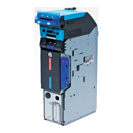
JCM GLOBAL UBA-RC Series Operation And Maintenance Manual (134 pages)
Banknote Recycler
Brand:
JCM GLOBAL
| Category:
Ultrasonic Jewelry Cleaner
| Size: 8 MB
Table of Contents
Uba-Rc™ Series
3
Table of Contents
3
List of Figures
10
Description
15
Banknote Recycler
15
UBA-RC™ Series
15
UBA-RC Unit Assembly
15
1 General Information
15
Type Descriptions
16
Model Descriptions
16
Software Descriptions
16
Precautions
16
User Cautions
17
Installation Cautions
17
Mounting, Dismounting & Transportation
17
Preventive Maintenance
17
Banknote Fitness Requirements
18
Banknote Storage Requirements
18
Primary Features
18
Component Names
19
Specifications
20
Technical Specifications
20
Environmental Specifications
21
Electrical Specifications
21
Structural Specifications
21
Unit Dimensions
22
Entire Unit Outside Dimensions
22
Entire Unit Outside Dimensions (Continued)
23
Technical Contact Information
24
Americas
24
JCM American
24
Europe, Middle East, Africa & Russia
24
JCM Europe Gmbh
24
UK & Ireland
24
JCM Europe (UK Office)
24
Asia and Oceania
24
Japan Cash Machine Co., Ltd.(Hq)
24
JCM Gold (HK) Ltd
24
Installation Procedure
25
2 Installation
25
Cable Interconnection
26
DIP Switch Configuration
26
Jumper Configurations
26
Connector Pin Assignments
27
Connector Pin Assignments (Continued)
28
Connector Pin Assignments (Continued)
29
Retrieving Banknotes
30
Sending Retrieved Banknotes to the Cash Box
30
Sending Retrieved Banknotes to the Cash Box by Command
30
Retrieving Banknotes Directly
30
Preventive Maintenance
30
Restoring Banknotes
30
Restoring Banknotes Using the UBA Transport Unit
30
Clearing a Banknote Jam
31
Cleaning Procedure
31
Sensor Cleaning Procedure
31
Dispense Settings
31
Sensor and Roller Locations
33
Standard Interface Circuit Schematics
34
Operational Flowcharts
35
Operational Flowcharts (Continued 1)
36
Operational Flowcharts (Continued 2)
37
Operational Flowcharts (Continued 3)
38
Operational Flowcharts (Continued 4)
39
Operational Flowcharts (Continued 5)
40
Operational Flowcharts (Continued 6)
41
Operational Flowcharts (Continued 7)
42
3 Communications
43
Americas
43
Asia and Oceania
43
Europe, Middle East, Africa & Russia
43
Japan Cash Machine Co., Ltd.(Hq)
43
JCM American
43
JCM Europe (UK Office)
43
JCM Europe Gmbh
43
JCM Gold (HK) Ltd
43
UK & Ireland
43
Tool Requirements
45
Power Source Board Removal
45
Lifter Motor Encoder Board Assy Removal
45
4 Disassembly/Reassembly
45
Recycler CPU Board Assy Removal
46
Emission Side Double Note Sensor Removal
46
Upper & Lower Full Sensor Pt/Upper & Lower End Sensor LED Removal
47
Figure 4-6 Lifter Motor Bracket Removal
47
Figure 4-7 Lifter Motor Assy Removal
47
Figure 4-8 Rear Frame & Middle Frame Removal
47
Lifter Motor Assy Removal
47
Upper & Lower Full Sensor LED/ Upper & Lower End Sensor PT/ Lifter Home Position Sensor LED & PT Removal
48
Figure 4-9 Rear Transport Assy Removal
48
Figure 4-10 Left Frame Plate Removal
48
Figure 4-11 Frame Guide 4 Removal
48
Figure 4-12 Full Sensor Pts and End Sensor Leds Removal
48
Figure 4-13 Frame Guide 3 Removal
48
Upper & Lower Flapper Pusher Lever Solenoid Removal
49
Flapper Open/Close Circuit Board Removal
49
Figure 4-14 Full Sensor Leds, End Sensor Pts and Lifter Home Position Sensor LED/PT Removal
49
Figure 4-15 Upper & Lower Flapper Pusher Lever Solenoid Removal
49
Banknote Transaction Sensor/Transport Unit Encoder Board & Double Note Sensor PT Removal
50
Banknote Transaction Sensor & Box Sensor Board Removal
50
Figure 4-16 Flapper Open/Close Circuit Board Removals
50
Figure 4-17 Banknote Transaction Sensor/Transport Unit Encoder Circuit Board & Double Note Sensor Removal
50
Figure 4-18 Banknote Transaction Sensor & Box Detection Circuit Board Removal
50
Recycler Encoder Board Removal
51
Upper & Lower Recycler Transport Motor Assy Removal
51
Figure 4-19 Recycler Encoder Circuit Board Removal
51
Figure 4-20 Gear & Shaft Removal
51
Figure 4-21 Recycler Transport Motors Removal
51
Pick Roller Removal
52
Figure 4-22 Rear Transport Upper Frame & Shaft Removal
52
Figure 4-23 Timing Belt Cover Removals
52
Figure 4-24 Timing Belt/Pulley Removal
52
Timing Belt Removal
52
Feed Roller Removal
53
Figure 4-25 RC Centering Guide Removal
53
Figure 4-26 End Lever Removal
53
Figure 4-27 Pick Roller Removal
53
Figure 4-28 RC Transport Race Removal
53
Figure 4-29 Transport Race Shaft Removal
53
Impeller and Stop Roller Removal
54
Figure 4-30 Feed Roller Removal
54
Figure 4-31 Flapper Removals
54
Figure 4-32 Spring Removals
54
Figure 4-33 Impeller Shaft Removals
54
O-Ring (Pusher Plate) Removal
55
Roller Timing Belt and O-Ring Removal
55
Figure 4-34 Impeller & Stop Roller Removal
55
Figure 4-35 Pusher Mechanism Removal
55
Figure 4-36 O-Ring Removals
55
Figure 4-37 Pusher Plate Removal
55
Figure 4-38 Pusher Drive Gear Removal
56
Figure 4-40 Pusher Timing Belt Replacement
56
Figure 4-42 Pulley & O-Ring Removal
56
Figure 4-43 Pusher Plate Removal
56
Pusher Plate Re-Installation
56
Entire System Wiring Diagram
57
Figure 5-1 UBA-RC Entire System Wiring Diagram (24V)
57
5 Wiring Diagrams
57
Transport Unit & Frame Unit Wiring Diagram (Partial)
58
Figure 5-2 UBA-RC Transport Unit/Frame Unit System Wiring Diagram (Part 1)
58
Figure 5-3 UBA-RC Frame Unit System Wiring Diagram (Part 2)
59
Download and Installation Workbench Tool Requirements
61
JCM Tool Suite Standard Edition Installation
61
Figure 6-1 Tool and Harness Connection
61
Figure 6-2 Setup.exe Location
61
Figure 6-3 Install Shield Wizard Screen
61
Figure 6-4 Installation File Extracting Screen
62
Figure 6-5 Customer Information Screen
62
Figure 6-6 Destination Folder Screen
62
Figure 6-7 Current Settings Confirmation
62
Figure 6-8 Installation Status Confirmation
62
Figure 6-9 Installation Completion Screen
62
6 Performance Tests
61
JCM Tool Suite Standard Edition
63
Firmware Download Procedure
63
Figure 6-10 JCM Tool Suite Short-Cut Icon
63
Figure 6-11 JCM Tool Suite Standard Edition
63
Figure 6-12 UBA-RC DIP Switch Setting
63
Figure 6-13 DIP Switch Location
63
Figure 6-14 Select Download
63
Figure 6-15 Invalid File! Dialog Pop-Up Screen
63
Figure 6-19 Download Progress Screen
64
Calibration
65
When to Calibrate
65
Calibration Tool Requirements
65
UBA-RC Reference Paper
65
Placing the Reference Paper
65
Calibration and Testing Program
65
Sensor Calibration and Performance Testing
65
Figure 6-21 Download Completed Screen
65
Figure 6-22 KS-087 Reference Paper
65
Figure 6-23 Reference Paper Insertion
65
Figure 6-24 UBA Transport DIP Switch Setting
66
Figure 6-25 DIP Switch Setting
66
Figure 6-26 DIP Switch Location
66
Figure 6-27 Model Information Screen
66
Figure 6-29 UBA-RC Maintenance Tool Screen 1
66
Figure 6-30 UBA-RC Maintenance Tool Screen 2
66
Figure 6-32 UBA-RC Maintenance Tool Screen 4
67
Figure 6-33 UBA-RC Maintenance Tool Screen 5
67
Figure 6-34 UBA-RC Maintenance Tool Screen 6
67
Model Information Confirmation
68
Figure 6-36 UBA-RC Maintenance Tool Screen 8
68
Figure 6-38 Calibration Completed Dialog Box
68
Figure 6-39 Serial No. Screen Button Location
68
Figure 6-41 Model Information Saving Screen 2
68
Reading the Model Information
69
Reading the UBA-RC Maintenance Tool Version
69
Figure 6-42 Model Information Saving Completed Screen
69
Figure 6-43 Sensor Calibration Screen Button
69
Individual Calibration and Performance Test
70
Sensor Test Screen
70
Individual Calibration
70
Double Note Detection Sensor Calibration
70
Figure 6-48 Sensor Test Selection
70
Figure 6-49 Test Function Listing Screen
70
Figure 6-50 Calibration Test Function Screen Buttons
70
Figure 6-51 Load Sensor Data
70
Load Sensor Data
70
Individual Performance Test
71
Figure 6-52 Double Note Detection Sensor
71
Figure 6-53 RC Full Sensor
71
Figure 6-54 Test Function Screen Buttons
71
Get All Sensor State
73
Performance Test Without a PC
74
Performance Test Without PC Procedure
75
Banknote Acceptance Test
75
Entire UBA-RC Unit Exploded View
77
Figure 7-1 Entire UBA-RC Unit Exploded View
77
Entire UBA-RC Unit Parts List
78
7 Exploded Views and Parts Lists
77
UBA-RC Frame Unit 1 Exploded View
79
Figure 7-2 UBA-RC Frame Unit 1 Exploded View
79
UBA-RC Frame Unit 1 Parts List
80
UBA-RC Frame Unit 2 Exploded View
81
Figure 7-3 UBA-RC Frame Unit 2 Exploded View
81
UBA-RC Frame Unit 2 Parts List
82
UBA-RC Frame Unit 3 Exploded View
83
Figure 7-4 UBA-RC Frame Unit 3 Exploded View
83
UBA-RC Frame Unit 3 Parts List
84
UBA-RC Frame Unit 4 Exploded View
85
Figure 7-5 UBA-RC Frame Unit 4 Exploded View
85
UBA-RC Frame Unit 4 Parts List
86
UBA-RC Frame Unit 5 Exploded View
87
Figure 7-6 UBA-RC Frame Unit 5 Exploded View
87
UBA-RC Frame Unit 5 Parts List
88
UBA-RC RC Space 1 Exploded View
89
Figure 7-7 UBA-RC RC Space 1 Exploded View
89
UBA-RC RC Space 1 Parts List
90
UBA-RC RC Space 2 Exploded View
91
UBA-RC RC Space 2 Parts List
91
Figure 7-8 UBA-RC RC Space 2 Exploded View
91
UBA-RC RC Space 3 Exploded View
92
Figure 7-9 UBA-RC RC Space 3 Exploded View
92
UBA-RC RC Space 3 Parts List
93
UBA-RC RC Space 4 Exploded View
94
Figure 7-10 UBA-RC RC Space 4 Exploded View
94
UBA-RC RC Space 4 Parts List
95
UBA-RC RC Space 5 Exploded View
96
Figure 7-11 UBA-RC RC Space 5 Exploded View
96
UBA-RC RC Space 5 Parts List
97
UBA-RC Rear Transport Assembly 1 Exploded View
98
UBA-RC Rear Transport Assembly 1 Parts List
98
Figure 7-12 UBA-RC Rear Transport Assembly 1 Exploded View
98
UBA-RC Rear Transport Assembly 2 Exploded View
99
Figure 7-13 UBA-RC Rear Transport Assembly 2 Exploded View
99
UBA-RC Rear Transport Assembly 2 Parts List
100
UBA-RC Rear Transport Assembly 3 Exploded View
101
Figure 7-14 UBA-RC Rear Transport Assembly 3 Exploded View
101
UBA-RC Rear Transport Assembly 3 Parts List
102
UBA-RC Rear Transport Assembly 4 Exploded View
103
Figure 7-15 UBA-RC Rear Transport Assembly 4 Exploded View
103
UBA-RC Rear Transport Assembly 4 Parts List
104
UBA-RC Rear Transport Assembly 5 Exploded View
105
Figure 7-16 UBA-RC Rear Transport Assembly 5 Exploded View
105
UBA-RC Rear Transport Assembly 5 Parts List
106
UBA-RC Rear Transport Assembly 6 Exploded View
107
Figure 7-17 UBA-RC Rear Transport Assembly 6 Exploded View
107
UBA-RC Rear Transport Assembly 6 Parts List
108
WBA-SH2 Cash Box Exploded View 1
109
WBA-SH2 Cash Box Parts List 1
109
Figure 7-18 WBA-SH2 Cash Box Exploded View 1
109
WBA-SH2 Cash Box Exploded View 2
110
Figure 7-19 WBA-SH2 Cash Box Exploded View 2
110
Table 7-19 WBA-SH2 Cash Box Parts List 2
111
WBA-SH2 Cash Box Parts List 2
111
WBA-SH2 Cash Box Exploded View 3
112
WBA-SH2 Cash Box Parts List 3
112
WBA-SH2 Cash Box Exploded View 4
113
WBA-SH2 Cash Box Parts List 4
114
Table 7-21 WBA-SH2 Cash Box Parts List 4
114
WBA-SH2 Cash Box Exploded View 5
115
WBA-SH2 Cash Box Parts List 5
116
Table 7-22 WBA-SH2 Cash Box Parts List 5
116
UBA-RC Large Cash Box Frame Unit Exploded View
118
UBA-RC Large Cash Box Frame Unit Parts List
118
Figure 7-23 UBA-RC Large Cash Box Frame Unit Exploded View
118
Table 7-23 UBA-RC Large Cash Box Frame Unit Parts List
118
Optional Lock Unit Exploded View
119
Figure 7-24 UBA-RC Optional Lock Unit Exploded View
119
Optional Lock Unit Parts List
120
Table 7-24 UBA-RC Optional Lock Unit Parts List
120
8 Index
121
A Troubleshooting
123
Introduction
123
Troubleshooting Overview
123
Malfunction LED Error Codes
123
LED Indicator Conditions
123
Table A-1 UBA Unit LED Code Conditions
123
Table A-2 RC Unit LED Color Type Error Code Conditions
124
Table A-3 Recycler Unit LED Code Conditions
125
Table A-4 Various Recycler Unit LED Flashing Error Code Conditions
125
UBA-RC Recycler Unit Width and Length Guide Replacement Procedure
126
Length Guide Replacement
126
Length Guide Installation
126
Figure A-1 Opening the Recycler Unit Door
126
Figure A-2 Length Guide Removal
126
Figure A-3 New Length Guide Installation 1
126
Width Guide Replacement
127
Figure A-7 Additional Maintenance Equipment Requirements
128
Table A-5 Additional Maintenance Equipment Parts List
128
B Glossary
129
Advertisement
Advertisement
Related Products
JCM GLOBAL UBA Series
JCM GLOBAL UBA-1x-SS Series
JCM GLOBAL UBA-11-SS
JCM GLOBAL UBA-12-SS
JCM GLOBAL UBA-14-SS
JCM GLOBAL UBA-24-SS
JCM GLOBAL UBA-25-SS
JCM GLOBAL UBA-x4-SS Series
JCM GLOBAL UBA-10-SS
JCM GLOBAL UBA Pro RT Series
JCM GLOBAL Categories
Bank Note Validator
Industrial Equipment
Cash Register
Ultrasonic Jewelry Cleaner
Payment Terminal
More JCM GLOBAL Manuals
Login
Sign In
OR
Sign in with Facebook
Sign in with Google
Upload manual
Upload from disk
Upload from URL