Sign In
Upload
Manuals
Brands
iWave Manuals
Motherboard
iW-RainboW-G42P
iWave iW-RainboW-G42P Manuals
Manuals and User Guides for iWave iW-RainboW-G42P. We have
1
iWave iW-RainboW-G42P manual available for free PDF download: Hardware User's Manual
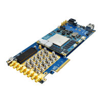
iWave iW-RainboW-G42P Hardware User's Manual (61 pages)
Zynq Ultrascale+ RFSoC (ZU29/39/49DR) SOM Development Platform
Brand:
iWave
| Category:
Motherboard
| Size: 4 MB
Table of Contents
Table of Contents
4
Introduction
7
Purpose
7
Overview
7
List of Acronyms
7
Table 1: Acronyms & Abbreviations
7
References
9
Table 2: Terminology
9
Architecture and Design
10
Zynq Ultrascale+ Rfsoc (ZU29/39/49DR) SOM Carrier Board Block Diagram
10
Figure 1: Zynq Ultrascale+ Rfsoc (ZU29/39/49DR) SOM Carrier Board Block Diagram
10
Zynq Ultrascale+ Rfsoc (ZU29/39/49DR) SOM Carrier Board Features
11
Board to Board Connectors
13
Board to Board Connector1
13
Figure 2: Board to Board Connector1
13
Board to Board Connector2
14
Figure 3: Board to Board Connector2
14
PS Interface Features
15
PS-GTR Transceivers
15
Figure 4: Pcie X4 Connector
15
Table 3: Pcie X4 M.2 Connector Pin Assignment
16
Figure 5: Display Port Connector
18
Table 4: Display Port Type-C Pin Assignment
19
Gigabit Ethernet Port1
20
Figure 6: Gigabit Ethernet Connector1
20
Usb2.0 Otg Type-C Connector
21
Figure 7: USB OTG Connector
21
Micro SD Port
22
Figure 8: Standard SD Connector
22
Usb Type-C Debug Connector (Jtag/Uart Usb Module)
23
Figure 9: Debug UART Connector
23
Interface Features
24
High Speed DAC/ADC RF SMA Connectors
24
Figure 10 : RF SMA Connectors
24
Figure 11 : RF Sampling Block Diagram
25
Table 5 : RF SMA Connectors Pinout
26
FMC+ HSPC Connector
28
Figure 12: FMC+ Connector
28
Figure 13: FMC+ HSPC Connector Pin out
29
Table 6: FMC+ HPC Connector Pin Assignment
30
Pcie X8 Edge Connector
47
Figure 14 : PL Pcie X8 Edge Connector
47
Table 7: Pciex8 Edge Pin Assignment
47
Additional Features
51
Sync and Reference Clock SMA Connectors
51
Figure 15 : Sync and Reference Clock SMA Connectors
51
Reset Push Button
52
Figure 16 : Reset Push Button
52
Table 8 : Sync and Reference Clock SMA Connectors Pinout
52
RTC Cell Header
53
Figure 17: RTC Coin Cell Holder
53
Technical Specification
54
Power Input Requirement
54
Figure 18: ATX Power Connector
54
Table 9: Power Input Requirement
54
Power Output Specification
55
Table 10: Power Output Specification
55
Environmental Characteristics
56
Environmental Specification
56
Rohs Compliance
56
Electrostatic Discharge
56
Table 11: Environmental Specification
56
Mechanical Characteristics
57
Carrier Board Mechanical Dimensions
57
Figure 19: Carrier Board Mechanical Dimension - Top and Bottom View
57
Figure 20: Board Mechanical Dimension - Side View
57
FAN Sink Fixing Procedure on SOM with Carrier Board
58
Figure 21: Zynq Ultrascale+ SOM with Fan Sink Fixing Procedure
58
Ordering Information
59
Table 12: Orderable Product Part Numbers
59
Appendix
60
Table 13: Low Pass Filters
60
Table 14: Band Pass Filters
60
Advertisement
Advertisement
Related Products
iWave iW-RainboW-G15S
iWave iW-RainboW-G21D
Iwave iW-RainboW-G15M
iWave iW-RainboW-G15D
iWave iW-RainboW-G25D
iWave iW-RainboW-G27M
iWave iW-RainboW-G20M
iWave iW-RainboW-G18D
iWave iW-RainboW-G20D
iWave iW-RainboW-G22D
iWave Categories
Motherboard
Computer Hardware
Single board computers
Control Unit
Microcontrollers
More iWave Manuals
Login
Sign In
OR
Sign in with Facebook
Sign in with Google
Upload manual
Upload from disk
Upload from URL