Sign In
Upload
Manuals
Brands
INVT Manuals
Inverter
GD200-037G/045P-4
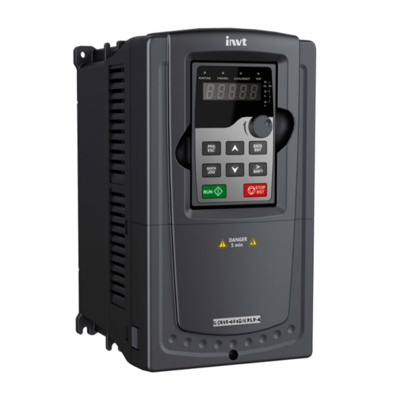
INVT GD200-037G/045P-4 Manuals
Manuals and User Guides for INVT GD200-037G/045P-4. We have
1
INVT GD200-037G/045P-4 manual available for free PDF download: Operation Manual
INVT GD200-037G/045P-4 Operation Manual (267 pages)
Goodrive200 Series
Brand:
INVT
| Category:
Inverter
| Size: 8 MB
Table of Contents
Preface
2
Table of Contents
3
Safety Definition
6
Warning Symbols
6
Safety Precautions 1
6
What this Chapter Contains
6
Safety Guidelines
7
Maintenance and Replacement of Components
9
What to Do after Scrapping
9
Unpacking Inspection
10
Application Confirmation
10
Environment
10
Quick Start-Up 2
10
What this Chapter Contains
10
Installation Confirmation
11
Basic Commission
12
Basic Principles
13
The Main Circuit Diagram
13
Product Overview 3
13
What this Chapter Contains
13
Product Specification
14
Name Plate
16
Type Designation Key
17
Rated Specifications
17
Structure Diagram
18
Product Structure Diagram
19
Mechanical Installation
20
Installation Environment
20
Installation Guidelines 4
20
What this Chapter Contains
20
Installation Direction
21
Installation Manner
22
Installation Direction of the Inverter
22
Single Installation
23
Multiple Installations
23
Parallel Installation
23
Vertical Installation
24
Tilt Installation
25
Standard Wiring
26
Wiring Diagram of Main Circuit
26
Terminals Figure of Main Circuit
26
1.5~2.2 Kw Terminals of Main Circuit
27
4~5.5 Kw Terminals of Main Circuit
27
7.5~11Kw Terminals of Main Circuit
27
15~18Kw Terminals of Main Circuit
27
22~30Kw Terminals of Main Circuit
28
37~55 Kw Terminals of Main Circuit
28
75~110Kw Terminals of Main Circuit
28
132~200Kw Terminals of Main Circuit
28
220~315Kw Terminals of Main Circuit
29
350~500Kw Terminals of Main Circuit
29
Wiring of Terminals in Main Circuit
30
Correct Installation of the Screw
31
360 Degree Grounding Technique
31
Wiring Diagram of Control Circuit
32
Terminals of Control Circuit
33
Input/Output Signal Connection Figure
35
U-Shaped Contact Tag
35
Layout Protection
36
NPN Modes
36
PNP Modes
36
Protecting Inverter and Input Power Cable in Short-Circuit Situations
36
Protecting the Motor and Motor Cable in Short-Circuit Situations
37
Protecting the Motor against Thermal Overload
37
Implementing a Bypass Connection
37
Keypad Operation Procedure 5
38
What this Chapter Contains
38
Keypad Displaying
41
Displayed State of Stopping Parameter
41
Displayed State of Running Parameters
41
Displayed State of Fault
41
Keypad Operation
42
Displayed State of Function Codes Editing
42
How to Modify the Function Codes of the Inverter
42
Displayed State
42
How to Set the Password of the Inverter
43
Sketch Map of Modifying Parameters
43
How to Watch the Inverter State through Function Codes
43
Sketch Map of Password Setting
43
Sketch Map of State Watching
44
Goodrive200 Inverters
45
Goodrive200 General Series Function Parameters
45
“Parameter Radix” Is Decimal (DEC)
45
Function Parameters 6
45
What this Chapter Contains
45
Basic Function Group
46
Keypad Running Command
47
MODBUS Communication
47
Function Codes
120
First Powering on
135
Check before Powering on
135
Original Powering Operation
135
Basic Operation Instruction 7
135
What this Chapter Contains
135
Relative Parameters Table
137
Vector Control
139
SVPWM Control
143
Recommendations
143
Torque Boost
143
Energy-Saving Running
144
V/F Slips Compensation Gain
144
Vibration Control
144
Torque Control
147
Parameters of the Motor
150
Start-Up and Stop Control
152
Relative Parameters List
154
Frequency Setting
157
Analog Input
162
Analog Output
164
Output Instructions
165
Digital Input
168
Digital Output
178
Simple PLC
181
PLC Finishes a Circle (or a Step)
182
Multi-Step Speed Running
184
PID Control
187
Simple Illustration of the PID Control Operation and Adjustment
188
General Steps of PID Parameters Setting
189
PID Inching
189
Control the Overshoot
189
Achieve the Stable State as Soon as Possible
189
Control Long Vibration
190
Control Short Vibration
190
Traverse Running
193
Pulse Counter
194
Fixed-Length Control
196
Fault Procedure
197
Alarm and Fault Indications
201
How to Reset
201
Fault History
201
Fault Tracking 8
201
What this Chapter Contains
201
Fault Instruction and Solution
201
Common Fault Analysis
207
The Motor Does Not Work
207
Other States
207
Motor Vibration
208
Overvoltage
208
Undervoltage Fault
209
Inverter Overheating
209
Abnormal Motor Heat
210
Stall During the Acceleration of the Motor
211
Overcurrent
212
Goodrive200 Inverters
213
Maintenance Intervals
213
Maintenance and Hardware Diagnostics 9
213
What this Chapter Contains
213
Cooling Fan
217
Capacitors
217
Replacing the Cooling Fan
217
Reforming the Capacitors
217
Change Electrolytic Capacitors
219
Power Cable
219
380V Charging Illustration of the Driven Device
219
Brief Instruction to MODBUS Protocol
220
Communication Protocol 10
220
What this Chapter Contains
220
Application of the Inverter
221
Rs485
221
RTU Mode
221
RTU Communication Frame Format
221
Code System
222
Error Detection Field
222
11-Bit Character Frame (BIT1~BIT8 Are the Digital Bits)
222
10-Bit Character Frame (BIT1~BIT7 Are the Digital Bits)
222
RTU Communication Frame Error Checkout
223
Bit Checkout of the Byte
223
CRC Check
224
RTU Command Code and Communication Data Illustration
225
Command Code: 03H
225
RTU Master Command Message (from the Master to the Inverter)
225
RTU Slave Response Message (from the Inverter to the Master)
226
Command Code: 06H
226
Command Code 08H for Diagnosis
227
Command Code: 10H, Continuous Writing
228
The Definition of Data Address
229
The Rules of Parameter Address of the Function Codes
229
The Address Instruction of Other Function in MODBUS
230
Fieldbus Ratio Values
233
Fault Message Response
234
Example of Writing and Reading
235
Example of Reading Command 03H
235
Example of Writing Command 06H
236
Common Communication Fault
237
Example of Continous Writing Command10H
237
Appendix A
239
What this Chapter Contains
239
Altitude Derating
240
Electric Power Network Specification
240
Carrier Frequency Derating
240
Motor Connection Data
241
EMC Compatibility and Motor Cable Length
241
Applicable Standards
241
EMC Regulations
242
Category C2
243
Category C3
243
Compatibility and Motor Cable Length
243
Technical Data
239
Ratings
239
Capacity
239
Derating
239
Appendix B
244
What this Chapter Contains
244
Inverter Chart
245
Wall Mounting
245
37-110Kw Wall Mounting
246
132-200Kw Wall Mounting
246
220-315Kw Wall Mounting
246
Flange Mounting
247
1.5-30Kw Flange Mounting
247
37-110Kw Flange Mounting
247
132-200Kw Flange Mounting
248
Floor Mounting
248
220-315Kw Floor Mounting
248
Dimension Drawings
244
Keypad Structure
244
Structure Chart
244
Installation Chart
244
Peripheral Options and Parts
250
Peripheral Wiring
250
Peripheral Options and Parts Appendix C
250
What this Chapter Contains
250
Power Supply
251
Cables
252
Power Cables
252
Control Cables
253
Routing the Cables
255
Checking the Insulation
255
Breaker and Electromagnetic Contactor
255
Reactors
257
Filters
258
Filter Type Instruction
259
Filters Selection Table
260
Braking System
260
Select the Braking Components
260
Select the Brake Resistor Cables
263
Place the Brake Resistor
263
Other Optional Parts
264
Further Information
265
Advertisement
Advertisement
Related Products
INVT GD200-045G/055P-4
INVT GD200-075G/090P-4
INVT GD200-090G/110P-4
INVT GD200-055G/075P-4
INVT GD200L-110G-4
INVT GD200L-090G/110P-4
INVT GD200L-220G/250P-4
INVT GD200L-400G-4
INVT GD200L-400P-4
INVT GD200L-350P-4
INVT Categories
Inverter
DC Drives
Servo Drives
Controller
I/O Systems
More INVT Manuals
Login
Sign In
OR
Sign in with Facebook
Sign in with Google
Upload manual
Upload from disk
Upload from URL