Sign In
Upload
Manuals
Brands
Intel Manuals
Server Board
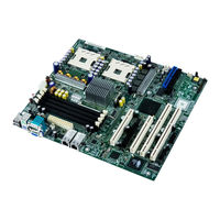
SE7320EP2
Intel SE7320EP2 Manuals
Manuals and User Guides for Intel SE7320EP2. We have
2
Intel SE7320EP2 manuals available for free PDF download: Technical Manual, Quick Start Manual
Intel SE7320EP2 Technical Manual (132 pages)
Technical Product Specification
Brand:
Intel
| Category:
Server Board
| Size: 0 MB
Table of Contents
Revision History
2
Table of Contents
3
1 Introduction
11
Server Board Use Disclaimer
11
2 Intel® Server Board SE7320EP2 / SE7525RP2 Overview
12
Intel® Server Boards SE7320EP2 and SE7525RP2 Feature Set
12
Figure 1. Block Diagram of Intel® Server Boards SE7320EP2 and SE7525RP2
13
3 Functional Architecture
14
Processor and Memory Subsystem
14
Processor Support
14
Table 1. Processor Support Matrix
14
Figure 2. CEK 'Passive' Component Stackup
16
Memory Subsystem
17
Figure 3. Memory Sub-System Block Diagram
17
Table 2. Memory Bank Labels
18
Figure 4. Memory Bank Label Definition
19
Table 3. I 2 C Addresses for Memory Module SMB
19
Intel® E7320 / E7525 Chipset
20
MCH Memory Architecture Overview
21
Table 4. Supported DDR2 Technology
21
Memory Controller Hub (MCH)
22
6300Esb ich
22
Table 5. 6300ESB ich GPIO Usage Table
24
Super I/O
25
Gpios
26
Table 6. Super I/O GPIO Usage Table
26
Serial Ports
27
BIOS Flash
27
SM Bus Block Diagram
28
Figure 5. Intel® Server Boards SE7320EP2 and SE7525RP2 SMBUS Block Diagram
28
4 Clock Generation and Distribution
29
Figure 6. Intel® Server Boards SE7320EP2 and SE7525RP2 Clock Distribution Diagram
30
5 PCI I/O Subsystem
31
PCI Subsystem
31
P32-A: 32-Bit/33-Mhz PCI Subsystem
31
Table 7. PCI Bus Segment Characteristics
31
Table 8. P32-A Configuration Ids
31
P64-B 66-Mhz PCI-X Subsystem
32
Table 9. P32-A Arbitration Connections
32
Table 10. P64-B Configuration Ids
32
PCI Express X8
33
PCI Express X16 (E7525 MCH Support Only)
33
Table 11. P64-B Arbitration Connections
33
Table 12. PCI Express X8 Connections
33
Table 13. PCI Express X16 (Port B) Connections
33
Video Controller
34
Video Modes
34
Table 14. Video Modes
34
Video Memory Interface
35
Host Bus Interface
35
Figure 7. Video Controller PCI Bus Interface
35
Network Interface Controller (NIC)
36
NIC Connector and Status Leds
36
Interrupt Routing
36
Legacy Interrupt Routing
36
APIC Interrupt Routing
37
Table 15. PCI and PCI-X Interrupt Routing/Sharing
37
Table 16. Interrupt Definitions
37
Serialized IRQ Support
38
Figure 8. Interrupt Routing Diagram
38
Figure 9. Interrupt Routing Diagram
39
PCI Error Handling
40
6 Bios
41
BIOS Architecture
41
BIOS Identification String
41
Figure 10. BIOS Identification String
41
System Initialization
42
Processors
42
Memory Subsystem
45
Table 17. Supported DIMM Module Capacities
45
Table 18. Supported DDR2-400 DIMM Populations
47
Table 19. Memory Error Handling in RAS Mode
47
Table 20. Memory Error Handling in Non-RAS Mode
48
Pci
51
PCI Express
52
Keyboard/Mouse
53
Universal Serial Bus (USB)
53
Ide
53
Removable Media Drives
53
Flash ROM
54
Bios Post
54
User Interface
54
System Diagnostic Screen
55
Quiet Boot / OEM Splash Screen
55
BIOS Boot Popup Menu
56
BIOS Setup Utility
56
Localization
56
Table 21. Sample BIOS Popup Menu
56
Console Redirection
57
Configuration Reset
57
Keyboard Commands
57
Table 22. BIOS Setup Keyboard Command Bar Options
57
Entering BIOS Setup
58
Table 23. BIOS Setup, Main Menu Options
58
Table 24. BIOS Setup, Advanced Menu Options
59
Table 25. BIOS Setup, Processor Configuration Sub-Menu Options
60
Table 26. BIOS Setup IDE Configuration Menu Options
61
Table 27. Mixed PATA-SATA Configuration with Only Primary PATA
63
Table 28. BIOS Setup, IDE Device Configuration Sub-Menu Selections
63
Table 29. BIOS Setup, Floppy Configuration Sub-Menu Selections
64
Table 30. BIOS Setup, Super I/O Configuration Sub-Menu
65
Table 31. BIOS Setup, USB Configuration Sub-Menu Selections
65
Table 32. BIOS Setup, USB Mass Storage Device Configuration Sub-Menu Selections
66
Table 33. BIOS Setup, PCI Configuration Sub-Menu Selections
67
Table 34. BIOS Setup, Memory Configuration Sub-Menu Selections
68
Table 35. BIOS Setup, Boot Menu Selections
69
Table 36. BIOS Setup, Boot Settings Configuration Sub-Menu Selections
69
Table 37. BIOS Setup, Boot Device Priority Sub-Menu Selections
70
Table 38. BIOS Setup, Hard Disk Drive Sub-Menu Selections
70
Table 39. BIOS Setup, Removable Drives Sub-Menu Selections
70
Table 40. BIOS Setup, CD/DVD Drives Sub-Menu Selections
71
Table 41. BIOS Setup, Security Menu Options
71
Table 42. BIOS Setup, Server Menu Selections
72
Table 43. BIOS Setup, System Management Sub-Menu Selections
72
Table 44. BIOS Setup, Serial Console Features Sub-Menu Selections
73
Table 45. BIOS Setup, Event Log Configuration Sub-Menu Selections
74
Table 46. BIOS Setup, Exit Menu Selections
74
Security
75
Operating Model
75
Table 47. Security Features Operating Model
75
Administrator/User Passwords and F2 Setup Usage Model
76
Password Clear Jumper
77
Flash Architecture and Flash Update Utility
78
Flash Update Utility
78
Update OEM Logo
80
7 Hardware and System Management
82
Hardware Management
82
Fan Speed Control Diagram
82
Figure 11. Fan Speed Control Block Diagram
82
Table 48. Monitored Components
82
Chassis Intrusion
83
Intel® Server Management (ISM) Software Support
83
Additional System Management Components
83
Console Redirection
83
Wired for Management (WFM)
84
Vital Product Data (VPD)
84
PXE BIOS Support
84
System Management BIOS (SMBIOS)
84
8 Sleep Support
85
Advanced Configuration and Power Interface (ACPI)
85
Sleep and Wake Functionality
86
Power Switch off to on
86
On to off (Operating System Absent)
86
On to off (Operating System Present)
86
On to Sleep (ACPI)
87
Sleep to on (ACPI)
87
System Sleep States
87
Table 49. Supported Wake Events
87
9 Error Logging
88
Error Sources and Types
88
SMI Handler
88
PCI Bus Error
88
Processor Bus Error
89
Memory Bus Error
89
Logging Format Conventions
89
Single-Bit ECC Error Throttling Prevention
89
Error Messages and Error Codes
89
POST Progress Codes and Messages
89
Table 50. POST Code Checkpoints
90
Table 51. Boot Block Initialization Code Checkpoints
92
Table 52. Boot Block Recovery Code Checkpoints
93
Table 53. DIM Code Checkpoints
94
BIOS Messages
95
Table 54. ACPI Runtime Checkpoints
95
Table 55. Memory BIOS Messages
95
Table 56. Boot BIOS Messages
95
Table 57. Storage Device BIOS Messages
96
Table 58. Virus Related BIOS Messages
98
Table 59. System Configuration BIOS Messages
98
Table 60. CMOS BIOS Messages
99
Table 61. Miscellaneous BIOS Messages
99
POST Error Messages and Handling
100
Table 62. USB BIOS Error Messages
100
Table 63. SMBIOS BIOS Error Messages
100
Table 64. POST Error Messages and Handling
101
Boot Block Error Beep Codes
102
Table 65. Boot Block Error Beep Codes
102
POST Error Beep Codes
103
POST Error Pause" Option
103
Table 66. POST Error Beep Codes
103
Table 67. Troubleshooting BIOS Beep Codes
103
10 Server Board SE7320EP2 and SE7525RP2 Connectors
104
10.1 Main Power Connector
104
Table 68. Power Connector Pin-Out (J12)
104
Table 69. Auxiliary Signal Connector (J5)
104
10.2 Memory Module Connector
105
Table 70. Auxiliary CPU Power Connector Pin-Out (J22)
105
Table 71. DIMM Connectors (J16,J18,J20,J21)
105
10.3 Processor Socket
107
Table 72. Socket 604 Processor Socket Pin-Out (J36, J37)
107
I C Header
110
Table 73. HSBP Header Pin-Out (J30,J54)
110
Table 74. OEM RMC Header Pin-Out (J33)
110
10.5 PCI Slot Connector
111
Table 75. P32-A 5V 32-Bit/33-Mhz PCI Slot Pin-Out (J10, J11)
111
Table 76. P64-B 3.3V 64-Bit/66-Mhz PCI-X Slot Pin-Out (J8, J9)
112
Table 77. PCI Express Slot Pin-Out (J13 for X8, J14 for X16)
113
10.6 Front Panel Connector
114
Table 78. Front Panel 34-Pin Header Pin-Out (J38)
114
10.7 VGA Connector
115
10.8 NIC Connector
115
Table 79. VGA Connector Pin-Out (J4)
115
Table 80. NIC1-82541PI(10/100/1000) Connector Pin-Out (JA1,JA2)
115
10.9 IDE Connector
116
10.10 SATA Connector
116
Table 81. ATA 40-Pin Connector Pin-Out (J43)
116
Table 82. SATA Connector Pin-Out (J28, J32)
116
10.11 USB Connector
117
Table 83. USB Connectors Pin-Out (J55)
117
Table 84. Optional USB Connection Header Pin-Out (J31)
117
10.12 Floppy Connector
118
10.13 Serial Port Connector
118
Table 85. Legacy 34-Pin Floppy Connector Pin-Out (J47)
118
Table 86. 9-Pin Header Serial B Port Pin-Out (J15)
118
10.14 Keyboard and Mouse Connector
119
10.15 Miscellaneous Headers
119
Fan Header
119
Table 87. Keyboard and Mouse PS/2 Connectors Pin-Out (J2)
119
Table 88. 3-Pin Fan Headers Pin-Out (J1, J48)
119
Table 89. 4-Pin Fan Headers Pin-Out (J7, J44, J45, J46)
119
Intrusion Cable Connector
120
System Recovery and Update Jumpers
120
Figure 12. System Recovery and Update Jumpers (J17)
120
Table 90. 6-Pin Fan Headers Pin-Out (J50)
120
Table 91. Intrusuper Ion Cable Connector (J19)Pin-Out
120
Table 92. System Recovery and Update Jumper Options
121
11 General Specifications
122
11.1 Absolute Maximum Ratings
122
Mean Time between Failure (MTBF)
122
Table 93. Absolute Maximum Ratings
122
Table 94. MTBF Calculation
122
11.3 Processor Power Support
123
11.4 Power Supply Specifications
123
Power Timing
123
Table 95. Intel® Xeon™ Processor DP TDP Guidelines
123
Table 96. Power Supply Voltage Specification
123
Figure 13. Output Voltage Timing
124
Table 97. Voltage Timing Parameters
124
Table 98. Turn on / off Timing
125
Voltage Recovery Timing Specifications
126
Figure 14. Turn on / Turn off Timing
126
Table 99. Transient Load Requirements
127
12 Product Regulatory Compliance
128
12.1 Product Safety Compliance
128
Product EMC Compliance
128
Mandatory/Standard: Certifications, Registration, Declarations
129
Product Regulatory Compliance Markings
129
12.2 Electromagnetic Compatibility Notices
129
Europe (CE Declaration of Conformity)
129
Australian Communications Authority (ACA) (C-Tick Declaration of Conformity)
129
Ministry of Economic Development (New Zealand) Declaration of Conformity
130
BSMI (Taiwan)
130
12.3 Replacing the Back up Battery
130
Appendix A: Integration and Usage Tips
131
Glossary
132
Advertisement
Intel SE7320EP2 Quick Start Manual (1 page)
Quick Start Guide
Brand:
Intel
| Category:
Server Board
| Size: 4 MB
Table of Contents
Tools Required
1
Fastener Identification Guide
1
Install the I/O Shield and Gasket
1
Install the Server Board
1
Prepare the Chassis
1
Install the Processor(S) and Heat Sink(S)
1
Record the Intel Server Chassis Product Code
1
Install the Server Board Bumper
1
Install the Chassis Standoffs
1
Advertisement
Related Products
Intel SE7320VP2
Intel SE7320VP2D2
Intel SE7320SP2 - 800MHZ Ecc Ddr Xeon
Intel SE7210TP1
Intel SE7501WV2ATA
Intel SE7520BD2
Intel SE7520BD2SATAD2
Intel SE7520JR2SCSID1 - Server Board SE7520JR2
Intel SE7525GP2
Intel SE7221BK1-E - Server Board - Mainboard
Intel Categories
Motherboard
Computer Hardware
Server
Desktop
Server Board
More Intel Manuals
Login
Sign In
OR
Sign in with Facebook
Sign in with Google
Upload manual
Upload from disk
Upload from URL