Sign In
Upload
Manuals
Brands
Intel Manuals
Motherboard
S5000XVNSATAR
Intel S5000XVNSATAR Manuals
Manuals and User Guides for Intel S5000XVNSATAR. We have
1
Intel S5000XVNSATAR manual available for free PDF download: Specification
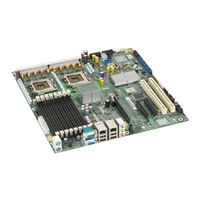
Intel S5000XVNSATAR Specification (107 pages)
Workstation Board
Brand:
Intel
| Category:
Motherboard
| Size: 1 MB
Table of Contents
Revision History
2
Table of Contents
3
1 Introduction
10
Chapter Outline
10
Server Board Use Disclaimer
10
2 Overview
11
Workstation Board Feature Set
11
Table 1. Workstation Board Features
11
Workstation Board Layout
12
Figure 1. Workstation Board Photograph
12
Workstation Board Connector and Component Layout
13
Figure 2. Major Board Components
14
Figure 3. Mounting Hole Positions
15
Workstation Board Mechanical Drawings
15
Figure 4. Component Positions
16
Figure 5. Restricted Areas on Side 1
17
Figure 6. Restricted Areas on Side 2
18
Figure 7. Restricted Areas on Side 2, "Detail B
19
Figure 8. CPU and Memory Duct Keepout
20
Figure 9. ATX I/O Layout
21
Workstation Board ATX I/O Layout
21
3 Functional Architecture
22
Figure 10. Functional Block Diagram
22
Intel ® 5000X Memory Controller Hub (MCH)
23
System Bus Interface
23
Processor Support
23
Table 2. Processor Support Matrix
23
Memory Subsystem
25
Figure 11. CEK Processor Mounting
25
Figure 12. Memory Layout
26
Table 3. I 2 C Addresses for Memory Module SMB
26
Table 4. Maximum Eight-DIMM System Memory Configruation - X8 Single Rank
27
Table 5. Maximum Eight-DIMM System Memory Configuration - X4 Dual Rank
27
Table 6. Maximum Eight-DIMM System Memory Configuration - X2 Quad Rank
27
Table 7. DIMM Population Rules
29
Figure 13. Minimum 2-DIMM Memory Configuration
30
Figure 14. Recommended Four DIMM Configuration
31
Figure 15. Single Branch Mode Sparing DIMM Configuration
32
Snoop Filter
33
Enterprise South Bridge (ESB2-E)
33
PCI Subsystem
33
Table 8. PCI Bus Segment Characteristics
34
Serial ATA Support
35
Parallel ATA (PATA) Support
36
USB 2.0 Support
36
Audio Codec
37
Figure 16. Audio Subsystem Block Diagram
37
SAS Controller
38
SAS RAID Support
38
SAS/SATA Connector Sharing
38
Network Interface Controller (NIC)
38
Figure 17. Rear I/O Panel Audio Connector
38
I/Oat)
39
MAC Address Definition
39
Table 9. NIC2 Status LED
39
3.6 Super I/O
40
Serial Ports
40
Floppy Disk Controller
40
Keyboard and Mouse Support
40
Wake-Up Control
40
Table 10. Serial B Header Pin-Out
40
System Health Support
41
Trusted Platform Module (TPM)
41
4 Platform Management
42
Figure 18. SMBUS Block Diagram
43
5 Connector/Header Locations and Pin-Outs
44
Board Connector Information
44
Table 11. Board Connector Matrix
44
Power Connectors
45
Table 12. Power Connector Pin-Out (J9B5)
45
System Management Headers
46
LCP/AUX IPMB Header
46
Table 13. 12-V Power Connector Pin-Out (J3J2)
46
Table 14. Power Supply Signal Connector Pin-Out (J9D1)
46
Table 15. P12V4 Power Connector Pin-Out (J5A2)
46
Table 16. LCP/AUX IPMB Header Pin-Out (J2J1)
46
IPMB Header
47
HSBP Header
47
SGPIO Header
47
Ses I 2 C
47
HDD Activity LED Header
47
Table 17. IPMB Header Pin-Out (J4J1)
47
Table 18. HSBP Header Pin-Out (J1J7, J1J2)
47
Table 19. SGPIO Header Pin-Out (J2H1, J1J5)
47
Table 20. SES I C Header Pin-Out (J1J3)
47
Table 21. HDD Activity LED Header Pin-Out (J2J3)
47
Front Panel Connector
48
I/O Connectors
48
NIC Connectors
48
Table 22. Front Panel SSI Standard 24-Pin Connector Pin-Out (J1E4)
48
Table 23. RJ-45 10/100/1000 NIC Connector Pin-Out (JA6A1, JA6A2)
48
IDE Connector
49
Table 24. IDE 40-Pin Connector Pin-Out (J2J2)
49
SATA/SAS Connectors
50
Serial Port Connectors
50
Table 25. SATA/SAS Connector Pin-Out (J1J1, J1H2, J1H1, J1G2, J1G1, J1F2)
50
Table 26. External DB9 Serial a Port Pin-Out (J7A1)
50
Keyboard and Mouse Connector
51
USB Connector
51
Table 27. Internal 9-Pin Serial B Header Pin-Out (J1B1)
51
Table 28. Stacked PS/2 Keyboard and Mouse Port Pin-Out (J9A1)
51
CD-IN Header
52
Audio Connectors
52
Table 29. External USB Connector Pin-Out (JA6A1, JA6A2)
52
Table 30. Internal USB Connector Pin-Out (J3J1)
52
Table 31. CD-IN Header Pin-Out (J4A1)
52
Fan Headers
53
Table 32. SSI 4-Pin Fan Header Pin-Out (J9J1, J5J1, J9B3, and J9B4)
53
Table 33. SSI 6-Pin Fan Header Pin-Out (J3H1, J3H2, J3H3, and J3H4)
53
6 Jumper Blocks
55
Figure 19. Jumper Blocks (J1C3, J1D1, J1D2, and J1E32)
55
Table 34. Server Board Jumpers (J1C3, J1D1, J1D2, and J1E3)
55
BMC Force Update Procedure
56
CMOS Clear and Password Reset Usage Procedure
56
BIOS Select Jumper
57
7 Intel Light Guided Diagnostics
58
Volt Standby LED
58
Figure 20. 5 Volt Standby Status LED Location
58
Fan Fault Leds
59
Figure 21. Fan Fault LED Locations
59
System ID LED and System Status LED
60
Figure 22. System ID LED and System Status LED Locations
60
Table 35. System Status LED
61
System Status LED - BMC Initialization
62
DIMM Fault Leds
62
Figure 23. DIMM Fault LED Locations
62
Processor Fault Leds
63
Post Code Diagnostic Leds
63
Figure 24. Processor Fault LED Locations
63
Figure 25. POST Code Diagnostic LED Location
64
8 Design and Environmental Specifications
65
Intel Workstation Board S5000XVN Design Specifications
65
Table 36. Workstation Board Design Specifications
65
Board-Level MTBF
66
Workstation Board Power Requirements
66
Figure 26. Power Distribution Block Diagram
67
Processor Power Support
68
Power Supply Output Requirements
68
Table 37. Intel ® Xeon ® Processor Dual Processor TDP Guidelines
68
Table 38. 550 W Load Ratings
68
Grounding
69
Remote Sense
69
Standby Outputs
69
Voltage Regulation
69
Capacitive Loading
70
Dynamic Loading
70
Table 39. Voltage Regulation Limits
70
Table 40. Transient Load Requirements
70
Ripple/Noise
71
Table 41. Capacitive Loading Conditions
71
Table 42. Ripple and Noise
72
Table 43. Output Voltage Timing
72
Timing Requirements
72
Figure 27. Output Voltage Timing
73
Table 44. Turn On/Off Timing
73
Figure 28. Turn On/Off Timing (Power Supply Signals)
74
Residual Voltage Immunity in Standby Mode
74
9 Regulatory and Certification Information
75
9.1 Product Regulatory Compliance
75
Product Safety Compliance
75
Product EMC Compliance - Class a Compliance
75
Certifications/Registrations/Declarations
76
Product Regulatory Compliance Markings
76
9.3 Electromagnetic Compatibility Notices
77
FCC Verification Statement (USA)
77
ICES-003 (Canada)
77
Europe (CE Declaration of Conformity)
78
VCCI (Japan)
78
BSMI (Taiwan)
78
RRL (Korea)
78
9.4 Restriction of Hazardous Substances (Rohs) Compliance
79
Appendix A: Integration and Usage Tips
80
Appendix B: BMC Sensor Tables
81
Table 45. BMC Sensors
83
Appendix C: POST Code Diagnostic LED Decoder
96
Figure 29. Diagnostic LED Placement Diagram
96
Table 46. POST Progress Code LED Example
96
Table 47. Diagnostic LED POST Code Decoder
97
Appendix D: POST Code Errors
100
Table 48. POST Error Messages and Handling
100
Table 49. POST Error Beep Codes
102
Table 50. BMC Beep Codes
102
Appendix E: Supported Intel Server Chassis
103
Glossary
104
Reference Documents
107
Advertisement
Advertisement
Related Products
Intel S5000XVNSASR
Intel S5000XVN - Workstation Board Motherboard
Intel S5000XVNSATA
Intel S5000PSL
Intel S5000PSLROMB
Intel S5000PSLROMBR - Server Board With Xeon Dualcore Support
Intel S5000PSLSAS
Intel S5000PSLSASR
Intel S5000VSA4DIMM
Intel S5000VSASASR - Xeon 50XX 51XX 53XX 54XX 4 SAS Port 8 FBDIMM Slots Motherboard
Intel Categories
Motherboard
Computer Hardware
Server
Desktop
Server Board
More Intel Manuals
Login
Sign In
OR
Sign in with Facebook
Sign in with Google
Upload manual
Upload from disk
Upload from URL