Sign In
Upload
Manuals
Brands
Inovance Manuals
DC Drives
MD500-PLUS Series
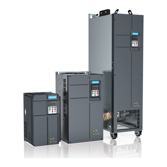
Inovance MD500-PLUS Series AC Drive Manuals
Manuals and User Guides for Inovance MD500-PLUS Series AC Drive. We have
6
Inovance MD500-PLUS Series AC Drive manuals available for free PDF download: Software Manual, Hardware Manual, Installation Manual, Quick Manual, Startup Procedure
Inovance MD500-PLUS Series Software Manual (718 pages)
General Purpose AC Drive
Brand:
Inovance
| Category:
DC Drives
| Size: 10 MB
Table of Contents
Preface
2
Table of Contents
4
Parameter List
8
List of Function Parameters
8
List of Monitoring Parameters
89
Parameter Groups
93
F0 Basic Parameter Group
93
F1 Parameters of Motor 1
107
F2 Vector Control Parameters of Motor 1
118
F3 V/F Control Parameters
135
F4 Input Terminal
147
F5 Output Terminal
186
F6 Start/Stop Control
208
F7 Key and Display
218
F8 Auxilliary Function
224
F9 Fault and Protection
241
FA Process Control PID
269
FB Wobble, Fixed Length, and Count
279
FC Multi-Reference and Simple PLC
285
FD Communication Parameters
303
FE User-Defined Parameters
313
FP User Parameters
321
A0 Torque Control and Restricting Parameters
323
A1 Virtual DI and DO Parameters
327
A5 Control Optimization Parameters
352
A6 AI Curve
357
A9 Vector Control Supplementary Parameters
365
AC AI/AO Correction
383
AF Process Data Address Mapping Parameters
393
B0 Control Mode, Linear Speed, and Roll Diameter Parameters
409
B1 Tension Settings
424
B2 Taper
436
B6 Communication Free Mapping Configuration Parameters
442
U0 Basic Monitoring Parameters
469
U1 Tension Control Monitoring Parameters
490
Function Application
494
Drive Configuration
494
Command Sources
494
Setting Command Sources
494
Setting Commands through the Operating Panel
494
Setting Commands through Communication
495
Setting Commands through Terminals
496
Frequency Sources
502
Frequency Reference Input Mode
502
Selecting a Main Frequency Source
502
Setting the Main Frequency through the Operating Panel
503
Setting the Main Frequency through Ais
504
Setting the Main Frequency through Multi-Reference
509
Setting the Main Frequency through Simple PLC
512
Setting the Main Frequency through PID
513
Setting the Main Frequency through Communication
516
Selecting an Auxiliary Frequency Source
518
Selecting Frequency Superposition Input Mode
520
Setting the Frequency Reference Limits
524
Soperation at Frequencies Lower than the Lower Limit
524
Setting the Main Frequency through Pulse Reference
525
Start/Stop Mode
526
Startup Modes
526
Stop Modes
529
Acceleration/Deceleration Time Setting
532
Motor Configuration
533
Asynchronous Motor Auto-Tuning
533
Synchronous Motor Auto-Tuning
539
Control Terminal
542
DI Functions
542
DO Functions
552
VDI Terminal
557
Control Performance
566
Setting the V/F Curve
566
Output Current (Torque) Limit
573
Overvoltage Stall Suppression
575
Speed Loop
577
Slip Adjustment in Vector Control Mode
580
Over-Excitation in Vector Control Mode
580
Torque Upper Limit
580
Torque Control
583
Current Loop
587
Improving Performance of Field-Weakening Range
588
FVC Running and Performance Improvement
588
Auxiliary Control
592
Encoder Signal Processing
593
Synchronous Motor in PMVVC Mode
594
Synchronous Motor Electromagnetic Shorting
595
Wobble Control Function
598
Fixed Length Control Function
600
Count Function
601
PID Adjustment Methods
602
Application Control
605
Jog Running
605
Frequency Detection
607
Multi-Speed Reference
607
Frequency Detection (FDT)
608
Jump Frequency
609
Reverse Frequency Inhibition
611
Detection Width for Frequency Reach
612
Switchover Frequency of Acceleration/Deceleration Time
613
Detection Value for Frequency Reach
614
Current Detection
616
Zero Current Detection
616
Output Current Limit Violation
616
Detection Level of Current
617
Forward/Reverse Run Switchover Dead Zone Time
618
Timing Function
619
Upper and Lower Limits of AI1 Voltage Protection
621
IGBT Temperature
621
Cooling Fan Working Mode
621
Tension Control
621
Selecting a Control Mode
621
Open-Loop Torque Control
624
Closed-Loop Torque Control
625
Closed-Loop Speed Control
626
Roll Diameter Calculation
627
Linear Speed
632
Constant Linear Speed Control
634
Application Restrictions
634
Tension Setting
635
PID Closed-Loop Adjustment
635
Winding Speed Limit and Unwinding Reverse Tightening
638
PID Adjustment Limit
640
Tension Torque Compensation
641
Taper
651
Pre-Drive
653
Constant Linear Speed Mode
654
Optimization Parameters for Control Mode
655
Related I/O Functions
657
Monitoring
658
Fault and Protection
661
Startup Protection
661
Undervoltage and Overvoltage Thresholds and Fast Current Limit Protection
662
Phase Loss Protection
663
Overtemperature Protection
664
Overload Protection
665
Load Loss Protection
667
Overspeed Protection
668
Excessive Speed Deviation Protection
668
Power Dip Ride-Through
669
Fault Reset
672
Fault Protection Action Selection
672
Detection of Short-Circuit to Ground
676
Monitoring
676
User Settings
688
User-Defined Parameters
688
Sleep and Wakeup
691
Current Running Time Threshold
692
Communication
693
Parameter Communication Address
693
Parameter Introduction
693
Modbus Communication Protocol
696
Communication Data Frame Structure
697
Parameter Address Expression Rules
701
Group Fd: Communication Parameters
705
Fault Codes
707
List of Fault Codes
707
Advertisement
Inovance MD500-PLUS Series Installation Manual (173 pages)
General Purpose AC Drive
Brand:
Inovance
| Category:
DC Drives
| Size: 25 MB
Table of Contents
Preface
2
Table of Contents
4
AC Drive Models
7
Fundamental Safety Instructions
9
Installation Preparation
15
Installation Process
15
Installation Site Inspection
17
Environment
17
Clearances
18
Installation Direction
21
Installation Tools
22
Tools for Mechanical Installation
22
Wiring Tools
24
Required Accessories
25
Through-Hole Mounting Bracket
25
Grounding Bracket of Cable Shield
35
Bottom Mounting Bracket
35
Guide Rail
37
Dimensions Drawings
38
T1 to T9 Models
38
T10 to T12 Models (Without AC Output Reactor)
41
T10 to T12 Models (with AC Output Reactor)
42
T13 Models (Without Auxiliary Power Distribution Cabinet)
43
T13 Models (with Auxiliary Power Distribution Cabinet)
45
Unpacking and Transportation
47
Storage
47
Transportation before Unpacking
47
Packing Verification
51
Unpacking
58
Transportation and Lifting after Unpacking
59
Mechanical Installation (T1 to T9 Models)
64
Installation Method
64
Cabinet Design
64
Overview
64
Cabinet Clearance Requirements
64
Mounting Backplate
65
Cabinet Heat Dissipation Design
66
Installation Precautions
73
Backplate Mounting
73
Through-Hole Mounting
75
Removing and Installing the Cover
78
Removing the Cover
78
Installing the Cover
81
Installing the Grounding Bracket of Cable Shield
83
Installing the Conduit Box
86
Mechanical Installation (T10 to T12 Models)
90
Installation Method
90
Installation Precautions
90
Heat Dissipation Design
91
Installation in a Cabinet
94
Removing and Installing the Cover
100
Removing the Cover
100
Installing the Cover
101
Mechanical Installation (T13 Models)
103
Installation Method
103
Installation Precautions
103
Requirements on Ground Flatness
103
Installing Expansion Screws
104
Requirements on Foundation
105
Installing an External Braking Unit
106
Checklist of Mechanical Installation
107
Electrical Installation
109
Electrical Wiring Diagram
109
Inspection before Wiring
112
Main Circuit Connection
113
Main Circuit Terminals
113
Main Circuit Terminal Dimensions and Cable Selection
117
Wiring of Main Circuit Terminals
128
Requirements on Wiring of the Main Circuit
130
Protection Requirements
134
Control Circuit Connection
135
Control Circuit Terminals
135
Wiring of Control Circuit Terminals
137
Requirements on Selection and Routing of Control Circuit Cables
143
Cable Routing Requirements
145
Routing Recommendations
146
Grounding
151
Grounding Requirements
151
Grounding One AC Drive Alone
152
Grounding Multiple AC Drives Installed Side by Side
153
Grounding the Cabinet System
154
Communication Connection
155
RS485 Wiring
155
CAN Communication Wiring
157
Ethercat Wiring
159
PROFINET Wiring
160
Inspection after Wiring
161
Installation of Options
162
AC Input Reactor
162
Output Reactor
162
Fuses, Contactors, and Circuit Breakers
162
EMC Filter
162
Simple Filter
163
Magnetic Ring and Ferrite Clamp
164
Troubleshooting for Common EMC Interference Problems
167
Leakage Current Suppression
167
Earth Leakage Circuit Breaker Malfunction
167
Harmonic Suppression
169
Control Circuit Interference
170
High-Speed Pulse Interference
170
Common I/O Signal Interference
170
Communication Interference
171
RS485 and CAN Communication Interference
171
Ethercat and PROFINET Communication Interference
171
Encoder Feedback Signal Errors
172
Inovance MD500-PLUS Series Hardware Manual (175 pages)
General-purpose ac drive
Brand:
Inovance
| Category:
DC Drives
| Size: 66 MB
Table of Contents
Preface
2
Table of Contents
5
Product Model
7
Fundamental Safety Instructions
9
Product Information
15
Features
15
Nameplate and Model
16
Components
17
Overview
17
Components of T1 to T6 Models
17
Components of T7 to T9 Models
19
Components of T10 to T12 Models
20
Components of T13 Models
21
System Architecture
23
System Composition
23
Electrical Wiring Diagram
25
Main Circuit Terminals
28
Control Circuit Terminals
32
AC Drive Dimensions
35
T1 to T9 Models
35
T10 to T12 Models (Without AC Output Reactor)
38
T10 to T12 Models (with AC Output Reactor)
39
Overall Dimensions of T13 Models (Without Auxiliary Power Distribution Cabinet)
40
T13 Models (with Auxiliary Power Distribution Cabinet)
41
Options
43
List of Options
43
Option Installation
48
Through-Hole Mounting Bracket
48
Bottom Mounting Bracket
57
Guide Rail
59
Conduit Box
59
Cables
65
Main Circuit Cable
65
Selection of Control Circuit Cables
75
Peripheral Electrical Devices
76
Fuse, Contactor, and Circuit Breaker
76
AC Input Reactor
78
EMC Filter
89
Simple Filter
101
Braking Components
103
AFE Unit
109
Output Reactor
112
Magnetic Ring and Ferrite Clamp
126
Operating Panel
129
Expansion Cards
131
List of Expansion Cards
131
Installing the Expansion Card
132
Technical Data
134
Electrical Parameters
134
Technical Specifications
143
Maintenance
147
Routine Maintenance
147
Daily Inspection Items
147
Regular Maintenance
148
Main Circuit Insulation Test
149
Replacement of Quick-Wear Parts
150
Service Life of Quick-Wear Parts
150
Replacing the Cooling Fan
150
Replacing Theelectrolytic Capacitor
161
Refilling and Replacing the Coolant
162
Placing the Drain Hose of Waterproof Baffle
164
Replacing the Dust Filter Foam
165
Storage and Warranty
167
Compliance
169
Compliance List
169
CE Certification
169
Introduction to CE Certification
169
Requirement for Compliance with EMC Directive
170
Requirements for Compliance with the LVD
171
UL or Cul Certification
172
Advertisement
Inovance MD500-PLUS Series Hardware Manual (174 pages)
General-Purpose AC Drive
Brand:
Inovance
| Category:
DC Drives
| Size: 36 MB
Table of Contents
Preface
2
Table of Contents
4
AC Drive Models
6
Fundamental Safety Instructions
8
Product Information
14
Features
14
Nameplate and Model Number
15
Components
17
Overview
17
Components of T1 to T6 Models
17
Components of T7 to T9 Models
19
Components of T10 to T12 Models
20
Components of T13 Models
21
System Structure
23
System Connection Diagram
23
Electrical Wiring Diagram
24
Main Circuit Terminals
27
Control Circuit Terminals
31
Dimensions Drawings
34
T1 to T9 Models
34
T10 to T12 Models (Without AC Output Reactor)
37
T10 to T12 Models (with AC Output Reactor)
38
T13 Models (Without Auxiliary Power Distribution Cabinet)
39
T13 Models (with Auxiliary Power Distribution Cabinet)
41
Options
43
List of Options
43
Mounting Accessories
46
Through-Hole Mounting Bracket
46
Bottom Mounting Bracket
56
Guide Rail
58
Conduit Box
58
Cables
64
Main Circuit Cable
64
Selection of Control Circuit Cables
72
Peripheral Electrical Devices
72
Fuse, Contactor, and Circuit Breaker
72
AC Input Reactor
75
EMC Filter
86
Simple Filter
99
Braking Components
101
AFE Unit
107
Output Reactor
110
Magnetic Ring and Ferrite Clamp
124
Operating Panel
128
Extension Cards
130
List of Extension Cards
130
Installing Extension Cards
131
Technical Data
133
Electrical Specifications
133
Technical Specifications
145
Routine Maintenance and Inspection
149
Routine Inspection Items
149
Daily Inspection Items
149
List of Periodic Inspection Items
150
Main Circuit Insulation Test
151
Replacing Quick-Wear Parts
152
Service Life of Quick-Wear Parts
152
Replacing the Cooling Fan
152
Replacing Theelectrolytic Capacitor
161
Refilling and Replacing the Coolant
161
Placing the Drain Hose of Waterproof Baffle
163
Replacing the Dust Filter Foam
164
Storage and Warranty
166
Compliance
168
Compliance List
168
CE Certification
168
Introduction to CE Certification
168
Conditions for Compliance with the EMC Directive
169
Conditions for Compliance with the LVD
171
Ul/Cul Certification
171
Inovance MD500-PLUS Series Quick Manual (25 pages)
Brand:
Inovance
| Category:
Media Converter
| Size: 2 MB
Table of Contents
Fundamental Safety Instructions
4
Installation Location
8
Mounting Clearances
12
Wiring Diagram
16
Parameter Group
23
Troubleshooting
24
Inovance MD500-PLUS Series Startup Procedure (16 pages)
EtherNET/IP Card
Brand:
Inovance
| Category:
Computer Hardware
| Size: 1 MB
Table of Contents
Table of Contents
2
General Data
3
Purpose of this Document
3
Overview
4
Installation and Settings
5
Installing the MD500-EN1 Card
5
Hardware Layout
6
Communication Configuration
7
Communication Setup for MD500-EN1 Card and MD500-PLUS/MD520 AC Drive
7
Drive Parameters Mapping
9
AC Drive Fault Information
12
Project Examples
13
Inoproshop Project (Inovance's AM/AC Series Controllers)
13
Advertisement
Related Products
Inovance MD500T18.5G/22P(B)-PLUS
Inovance MD500T75G/90P(B)-PLUS
Inovance MD500T200G/250P-PLUS
Inovance MD500T220G/280P-PLUS
Inovance MD500-2T90G/110P-PLUS
Inovance MD500T55G-PLUS
Inovance MD500T45GB-PLUS
Inovance MD500T200G-PLUS
Inovance MD500T500G-PLUS
Inovance MD500T450G-L-PLUS
Inovance Categories
Servo Drives
DC Drives
Controller
Control Unit
Inverter
More Inovance Manuals
Login
Sign In
OR
Sign in with Facebook
Sign in with Google
Upload manual
Upload from disk
Upload from URL