Sign In
Upload
Manuals
Brands
Infranor Manuals
Control Unit
XtrapulsCD1-pm
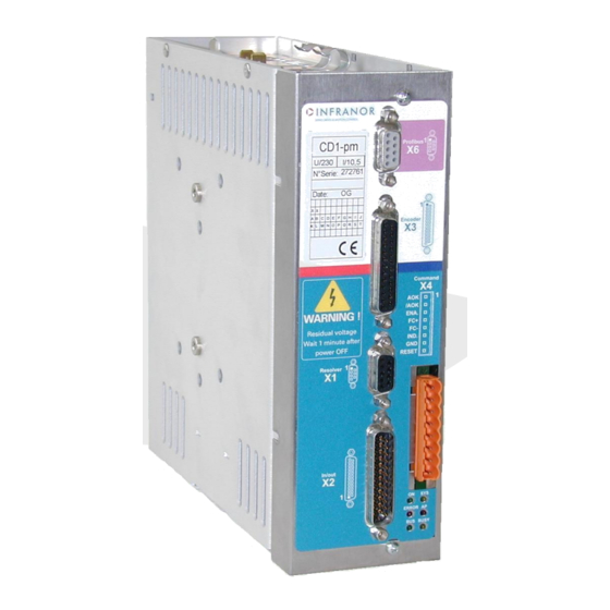
Infranor XtrapulsCD1-pm Manuals
Manuals and User Guides for Infranor XtrapulsCD1-pm. We have
2
Infranor XtrapulsCD1-pm manuals available for free PDF download: User Manual, Installation Manual
Infranor XtrapulsCD1-pm User Manual (55 pages)
Brand:
Infranor
| Category:
Control Unit
| Size: 0 MB
Table of Contents
Contents
5
Table of Contents
5
Chapter 1 - General Description
7
Introduction
7
Profibus Mode with Software Addressing
7
Profibus Mode with Hardware Addressing
7
Stand-Alone Mode
7
Architecture of a Positioner
8
Other Documents Required for the Commissioning
8
Chapter 2 - Commissioning
9
Commissioning Overview
9
Installation of the Pc Software
10
Checking the Positioner Hardware Configuration
10
Selection of the Operation Mode
10
Commissioning
10
Starting the "Vdsetup" Software
11
Motor Adjustment
11
Configuration of the Sensor Type
11
Selection of the Motor Type
12
Encoder Counting Protection
12
Parameter Adjustment for a Linear Motor
13
Maximum Application Speed
13
Configuration of the Thermal Sensor
13
I T PROTECTION
14
Servo Loop Adjustment
15
Regulator Parameters
15
Loop Adjustment with a Vertical Load
16
Rotation / Counting Direction
16
Parameter Saving
16
Motor Phasing at Power on
17
Incremental Encoder Outputs
17
Position Loop Setup
18
Applications with the Second Sensor Input
18
Second Position Sensor Feedback
19
Electronic Gearing Application
20
Cogging Torque Compensation
21
Chapter 3 - Functionalities
23
DESCRIPTION of the LOGIC I/Os
23
Logic Inputs
23
Logic Outputs
23
Limit Switches Adjustment
24
Brake Control
25
Profibus Address
25
Profibus Software Addressing
25
Profibus Hardware Addressing
25
Chapter 4 - Programming
26
General Description
26
Positioner Configuration
26
Position Scaling
26
Position Limit and Safety
27
Manual Movements
28
Brake Control and Amplifier Disabling
28
Positioning Profile
29
Position Modulo
29
POSITIONER I/Os
29
Second Sensor
30
Profibus Communication
30
Edition of a Sequence
30
Homing Sequence
32
Positioning Sequence
33
Speed Sequence
34
Torque Sequence
34
Gearing Sequence
35
Sequences Chaining
35
Programmable Outputs
37
Programmable Inputs
37
Programme Execution
37
Speed Limitation
38
Chapter 5 - Profibus Communication
39
Chapter 6 - Troubleshooting
40
Diagnostics
40
Xtrapulscd1-Pm FAULT Leds
40
Fault Reset
40
Fault Finding
40
System Fault
40
Non Stored Faults
40
Stored Faults
40
Operating Problems
45
Motor Does Not Move
45
Motor Supplied but no Torque
45
Shaft Locked, Eratic Oscillations or Rotation at Maximum Speed
45
Discontinuous Motor Rotation with Zero Torque Positions
45
Loud Crackling Noise in the Motor at Standstill
45
Loud Noise in the Motor at Standstill and When Running
46
Sequence Not Executed
46
Service and Maintenance
46
Appendix
47
Servo Controller Structure
47
Use of the Serial Link
48
Overview
48
Instructions List
49
Use of the Vt 100 Terminal
52
Configuration
52
Use of the Terminal
53
Fault Display
55
Advertisement
Infranor XtrapulsCD1-pm Installation Manual (40 pages)
PROFIBUS POSITIONER
Brand:
Infranor
| Category:
Servo Drives
| Size: 2 MB
Table of Contents
Content
4
Table of Contents
4
Chapter 1 - General Description
6
1- Introduction
6
Description / Compliance with the Standards
6
General Description
6
Reference to the Standards: "Ce" Certification
7
Reference to the Standards: "Ul" Listing
7
Other Documents Required for the Commissioning
7
Chapter 2 - Specifications
8
Main Technical Data
8
XTRAPULS CD1-Pm-230-/I POSITIONER
8
XTRAPULS CD1-Pm-400/I POSITIONER
8
COMMON SPECIFICATIONS to both POSITIONER VERSIONS XTRAPULS CD1-Pm-230/I and XTRAPULS CD1-Pm-400/I
9
Dimensions
12
XTRAPULS CD1-Pm-230/I POSITIONER
12
XTRAPULS CD1-Pm-400/1.8 to 7.2 a POSITIONER
12
XTRAPULS CD1-Pm-400/14 a POSITIONER
12
XTRAPULS CD1-Pm-400/30/45/70 and 90 a POSITIONER
12
BRAKING RESISTOR Dp 100/100, Dp 200/100, Dp 50/200, Dp 33/280 and Dp 16.5/560
13
Fastening
14
XTRAPULS CD1-Pm-230/I POSITIONER
14
XTRAPULS CD1-Pm-400/1.8 to 7.2 a POSITIONER
14
XTRAPULS CD1-Pm-400/14 a POSITIONER
14
XTRAPULS CD1-Pm-400/30/45/70 and 90 a POSITIONER
14
Multiaxes Cabinet Mounting
15
XTRAPULS CD1-Pm-230/I POSITIONER
15
XTRAPULS CD1-Pm-400/1.8 to 7.2 APOSITIONER
15
XTRAPULS CD1-Pm-400/14 APOSITIONER
15
XTRAPULS CD1-Pm-400/30/45/70 and 90 APOSITIONER
15
Chapter 3 - Inputs - Outputs
16
Connector Location
16
Leds
17
DRIVE FAULT Leds
17
X1: Resolver Connector
17
X2: Digital I/Osconnector
18
X3: Encoder Connector
20
X3 CONNECTOR for TTL INCREMENTAL ENCODER & HES INPUT (Sub D 25 Pins Female)
20
X3 CONNECTOR for Sincos INCREMENTAL ENCODER & HES INPUT (Sub D 25 Pins Female)
21
X3 CONNECTOR for ABSOLUTE SINGLE TURN SIN/COS ENCODER (Sub D 25 Pins Female)
22
X3 CONNECTOR for ENCODER OUTPUT (Sub D 25 Pins Female)
23
X4: Command Connector
24
Specifications of the Logic Inputs: Fc+, Fc-, Index, Enable, Reset
24
Specification of the "Aok" Logic Relay Output
25
X5: Rs-232 Connector
25
X6: Profibus
25
X8: Auxiliary Supply and Brake Connector
25
X9: POWER CONNECTOR: MAINS, MOTOR, BRAKING RESISTOR (CD1-Pm-230 V & 400 V)
26
Chapter 4 - Connections
27
Connection Diagrams
27
XTRAPULS CD1-Pm-230/I POSITIONER
27
XTRAPULS CD1-Pm-400/I POSITIONER
28
Serial Link Connection
28
Connection of a Backup Battery for the 24 VDC Auxiliary Supply
29
Connection Example for a Multiaxis Application
29
Wiring Recommendations
30
Ground Connections and Leakage Current
30
Connectors Shield Connection
31
CONNECTION VIEW of XTRAPULS CD1-Pm-400/30/45/70 and 90 a
32
Motor, Resolver and Encoder Cables
32
Serial Link Cables
33
Connection Cables of the Braking Resistor
33
Requirements of Compliance with the Ul Standards
34
Connection by Means of Faston Socket
34
24 V Supply
34
Power Supply and Ul Fuse Rating
34
XTRAPULS CD1-Pm-230/I DRIVE: CONNECTION DIAGRAM with PROTECTIONS by "UL" FUSES
35
XTRAPULS CD1-Pm-400/I DRIVE: CONNECTION DIAGRAM with PROTECTIONS by "UL" FUSES
36
Connection Example for a Ul Compliant Multiaxis Application
37
FIRST POWERING of the XTRAPULS CD1-Pm POSITIONER
37
Very Important
37
Switch on the 24 VDC Supply
37
SWITCH on the 230 VAC or 400 VAC SUPPLY (According to the Positioner Type)
37
Further Commissioning Procedure
37
Chapter 5 - Appendix
38
Hardware Adjustments of the Logic Board
38
Adjustment to Various Resolver Types
39
Use of the "Aok" Output
39
Energy Recuperation Via a Braking Resistor
40
Ordering Code
40
Advertisement
Related Products
Infranor XtrapulsCD1-k
Infranor XtrapulsCD1-a Series
Infranor XtrapulsCD1-a-230/4.5
Infranor XtrapulsCD1-a-230/2.25
Infranor XtrapulsCD1-a-230/7.5
Infranor XtrapulsCD1-a-230/10.5
Infranor XtrapulsCD1-a-230/16.5
Infranor XtrapulsCD1-EM-400/70
Infranor XtrapulsCD1-EM-400/90
Infranor XtrapulsCD1-pm-230/2.25
Infranor Categories
DC Drives
Amplifier
Controller
Servo Drives
Control Unit
More Infranor Manuals
Login
Sign In
OR
Sign in with Facebook
Sign in with Google
Upload manual
Upload from disk
Upload from URL