Table of Contents
Advertisement
Quick Links
Advertisement
Table of Contents

Related Manuals for Infranor XtrapulsCD1-pm


Summary of Contents for Infranor XtrapulsCD1-pm
- Page 1 XtrapulsCD1-pm User manual PROFIBUS POSITIONER...
- Page 2 XtrapulsCD1-pm - User manual Windows ® is a registered trade-mark of MICROSOFT ® CORPORATION. ® ® STEP7 is a registered trade-mark of SIEMENS...
- Page 3 27 January 2003 on waste electrical and electronic equipment (WEEE), all INFRANOR devices symbolizing a crossed-out wheel dustbin as shown in Appendix IV of have got a sticker the 2002/96/EC Directive This symbol indicates that INFRANOR devices must be eliminated by selective disposal and not with standard waste.
- Page 4 Sorting instructions may vary according to regions / countries. INFRANOR does not assume any responsibility for any physical or material damage due to improper handling or wrong descriptions of the ordered items. Any intervention on the items, which is not specified in the manual, will immediately cancel the warranty.
-
Page 5: Table Of Contents
XtrapulsCD1-pm - User manual Contents PAGE CONTENTS ..............................5 CHAPTER 1 - GENERAL DESCRIPTION ....................7 1 - INTRODUCTION ..........................7 1.1 – PROFIBUS MODE WITH SOFTWARE ADDRESSING ............7 1.2 – PROFIBUS MODE WITH HARDWARE ADDRESSING ............7 1.3 – STAND-ALONE MODE ......................7 2 - ARCHITECTURE OF A POSITIONER .....................8 3 - OTHER DOCUMENTS REQUIRED FOR THE COMMISSIONING ..........8... - Page 6 CHAPTER 5 – PROFIBUS COMMUNICATION ................... 39 CHAPTER 6 – TROUBLESHOOTING ....................40 1 - DIAGNOSTICS ..........................40 1.1 - XtrapulsCD1-pm FAULT LEDs ....................40 1.2 – FAULT RESET ........................40 2 – FAULT FINDING ........................... 40 2.1 – SYSTEM FAULT ........................40 2.2 –...
-
Page 7: Chapter 1 - General Description
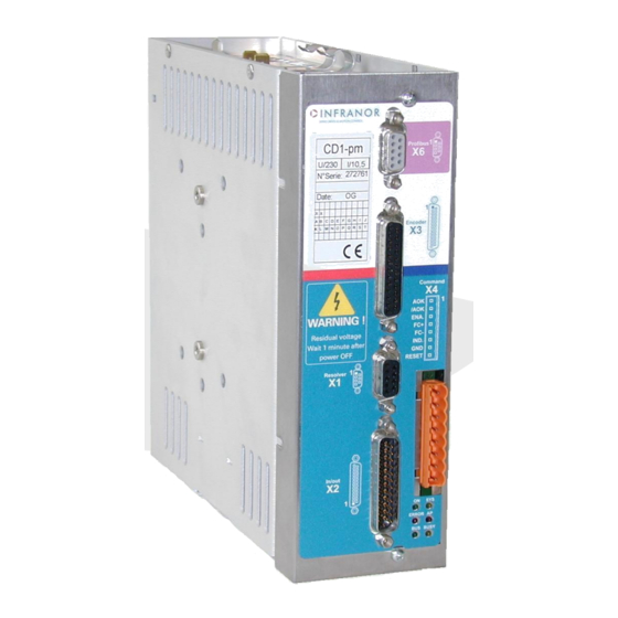
Series XtrapulsCD1-pm Profibus positioners are PWM servo amplifiers for the control of AC sinusoidal motors (brushless) equipped with a position sensor. The XtrapulsCD1-pm servo drive is available as a stand-alone single-axis block that includes all supplies and mains filter. It is available in both mains operated versions 230 V... -
Page 8: Architecture Of A Positioner
When disabled, its rotation is free and there is no current in the motor. 3 - OTHER DOCUMENTS REQUIRED FOR THE COMMISSIONING " XtrapulsCD1-pm Profibus positioner Installation Manual". " XtrapulsCD1-pm Profibus Communication Profile". Chapter 1 – General description... -
Page 9: Chapter 2 - Commissioning
XtrapulsCD1-pm - User manual Chapter 2 - Commissioning WARNING During the machine adjustments, some drive connection or parameterization errors may involve dangerous axis movements. It is the user's responsibility to take all necessary steps in order to reduce the risk due to uncontrolled axis movements during the operator's presence in the concerned area. -
Page 10: Installation Of The Pc Software
XtrapulsCD1-pm - User manual 2 – INSTALLATION OF THE PC SOFTWARE ® 1 The Visual Drive Setup software is PC compliant under Windows and allows an easy parameterization of the XtrapulsCD1-pm amplifiers. Please see our website www.infranor.com for downloading the "Visual Drive Setup" software. -
Page 11: Starting The "Vdsetup" Software
XtrapulsCD1-pm - User manual 6 - STARTING THE "VDSETUP" SOFTWARE • Connect the serial link RS232 between PC and amplifier. • Switch on the amplifier and start the Visual Drive Setup software on the PC, under WINDOWS ® If the message No serial communication found is displayed on the screen, click on OK and check the following... -
Page 12: Selection Of The Motor Type
The encoder counting protection of the XtrapulsCD1-pm amplifier range allows the detection of pulse counting errors and immediately disables the amplifier for reasons of security. -
Page 13: Parameter Adjustment For A Linear Motor
XtrapulsCD1-pm - User manual 7.4 - PARAMETER ADJUSTMENT FOR A LINEAR MOTOR The Motor encoder resolution parameter is calculated as follows: Motor magnets Pole pitch Motor pole pitch (mm) Motor encoder resolution = 1000 x Encoder signal pitch (µm) 1 encoder signal pitch = 4 counting increments... -
Page 14: I T Protection
XtrapulsCD1-pm - User manual 7.6.3 – WARNING THRESHOLD ADJUSTMENT Enter the sensor ohmic value (kOhm) corresponding to a warning temperature value. When the warning temperature is reached, the red front panel LED "ERROR" is blinking. Note: When using a CTN sensor, the warning ohmic value will be higher than or equal to the triggering ohmic value. -
Page 15: Servo Loop Adjustment
XtrapulsCD1-pm - User manual NOTE 2 The amplifier I t signal can be displayed on the digital oscilloscope by selecting the I t signal in the Channel menu. The threshold values of the I t signal, for the protection mode described above, are calculated as follows: Current limitation threshold (%) = Rated current (%)... -
Page 16: Loop Adjustment With A Vertical Load
XtrapulsCD1-pm - User manual For a complete adjustment, the Autotuning procedure must always be executed in Position mode (at power on, the amplifier is automatically in Position mode). But the amplifier position loop stability can also be tested in Speed mode. In this case, after the execution of the Autotuning procedure in PI²... -
Page 17: Motor Phasing At Power On
XtrapulsCD1-pm - User manual 11 - MOTOR PHASING AT POWER ON In the Incremental encoder configuration without HES, the motor Phasing procedure is executed according to the following diagram at each amplifier power up (standalone mode) : Power On ENABLE... -
Page 18: Position Loop Setup
14 – APPLICATIONS WITH THE SECOND SENSOR INPUT The XtrapulsCD1-pm amplifier has got 2 position sensor inputs : one for a resolver and another for an encoder. The position sensor input which is not used for the motor position feedback (encoder or resolver) is called Second Position Sensor input. -
Page 19: Second Position Sensor Feedback
XtrapulsCD1-pm - User manual 14.1 – SECOND POSITION SENSOR FEEDBACK Trajectory Position Speed Current loop Load Motor generator loop loop Load Motor position feedback Enable Scaling factor sensor Num / Den Resolver sensor feedback for the motor, and TTL incremental encoder for the second sensor is the default configuration. -
Page 20: Electronic Gearing Application
XtrapulsCD1-pm - User manual - For a resolver sensor type on the load: Position scaling factor Numerator = "Position resolution" parameter value (see “Position scaling parameters” window). Position scaling factor Denominator = 65536 x number of resolver shaft revolution for one motor shaft revolution. -
Page 21: Cogging Torque Compensation
XtrapulsCD1-pm - User manual Adjust the "Position scaling factor" (numerator / denominator) according to the desired gearing ratio as described below: - For an electronic gearing application with an encoder sensor type on the master axis, Gearing ratio = Gearing numerator / Gearing denominator = Motor shaft speed / Master encoder shaft speed. - Page 22 XtrapulsCD1-pm - User manual The Write cogging torque data into the drive function allows uploading in the amplifier the cogging torque value corresponding to a motor, if this value has previously been stored in the PC (*.COG file). For a brushless motor equipped with an incremental encoder, the Cogging torque compensation is only available if the encoder is providing one marker pulse per motor revolution.
-
Page 23: Chapter 3 - Functionalities
XtrapulsCD1-pm - User manual Chapter 3 – Functionalities 1 - DESCRIPTION OF THE LOGIC I/Os 1.1 - LOGIC INPUTS 1.1.1 - GLOBAL LOGIC INPUTS ENABLE Enabling authorized. This signal is a necessary condition for the motor enabling. INDEX/CLR Index input for the axis homing. This input can be used for resetting the position counter when this function is configured. -
Page 24: Limit Switches Adjustment
XtrapulsCD1-pm - User manual 1.2.2 - SEQUENCE CONTROLLED LOGIC OUTPUTS This signal indicates that a sequence is presently executed. This signal is activated when the motor reaches the position and remains enabled until the next motor movement. SPEED This signal indicates that the speed set point is reached during a movement of the motor. -
Page 25: Brake Control
The identity number of the XtrapulsCD1-pm positioners under Profibus is 0x00C7. 4.2 - PROFIBUS HARDWARE ADDRESSING In this operation mode, the XtrapulsCD1-pm address (1 to 125) is selected by means of the DIP micro-switches 1 to 7. DIP micro-switch 1 is the LSB and DIP micro-switch 7 is the MSB. -
Page 26: Chapter 4 - Programming
XtrapulsCD1-pm - User manual Chapter 4 - Programming 1 – GENERAL DESCRIPTION The XtrapulsCD1-pm amplifiers can get up to 128 pre-programmed sequences. Each sequence can be either : • a homing sequence (HOME) or • an absolute positioning sequence (ABSOLUTE) or •... -
Page 27: Position Limit And Safety
XtrapulsCD1-pm - User manual 2.2 – POSITION LIMIT AND SAFETY Following error threshold: defines the following error triggering threshold. It is important to correctly adjust this value in order to get a good protection. It can be adjusted like follows:... -
Page 28: Manual Movements
XtrapulsCD1-pm - User manual 2.3 – MANUAL MOVEMENTS There are 2 types of manual motion: - manual positioning: moving of the motor until a given position via the serial link. - manual jog: continuous movement when the JOG command is activated. -
Page 29: Positioning Profile
XtrapulsCD1-pm - User manual 2.5 – POSITIONING PROFILE Speed profile: trapezoidal or S-curve shape selection. Profile limit: when the Constant time profile limit mode is selected, for a small displacement, if the profile speed cannot be reached, the motor acceleration and deceleration are modified in order to get the same acceleration and deceleration times than the programmed profile. -
Page 30: Second Sensor
XtrapulsCD1-pm - User manual Sequence control: The IN1 to IN7 inputs can be used for selecting sequences (ticked off in the PC software). There are maximum 128 sequences that can be selected this way by inputs IN1 to IN7 (in binary code). The other inputs can be used for the start condition. - Page 31 XtrapulsCD1-pm - User manual Speed Defines the motion speed in rpm. When the parameter Max speed is modified, all speed values in the sequences are scaled accordingly. Ratio Slave motor gearing ratio factor for a GEARING sequence. This parameter defines the master/slave gearing ratio factor in %.
-
Page 32: Homing Sequence
XtrapulsCD1-pm - User manual 3.1 - HOMING SEQUENCE A homing sequence is defined by: - the motion speed, - the acceleration time, - the deceleration time, The parameter acceleration and deceleration times define the time with regard to the maximum speed parameter value. -
Page 33: Positioning Sequence
XtrapulsCD1-pm - User manual 3.2 - POSITIONING SEQUENCE A positioning sequence is defined by: - the position to be reached (absolute or relative), - the motion speed, - the acceleration time, - the deceleration time. The upper limit value for the position set point (absolute or relative) is + 2 x (position resolution parameter value) - 1. -
Page 34: Speed Sequence
XtrapulsCD1-pm - User manual 3.3 - SPEED SEQUENCE A speed sequence is defined by: - the speed set point, - the running time, - the acceleration time, - the deceleration time. When the running time exceeds 16000 ms, the stop condition can be used for stopping the sequence. -
Page 35: Gearing Sequence
XtrapulsCD1-pm - User manual 3.5 - GEARING SEQUENCE A gearing sequence is defined by: - the gearing distance, - the gearing ratio factor, - the gearing direction, - the acceleration time, - the deceleration time. At the start of the sequence, the motor speed is ramping according to the acceleration parameter value. When the motor speed value reaches the second sensor velocity, the motor position is locked in phase and frequency with the second sensor position according to the gearing ratio value. - Page 36 XtrapulsCD1-pm - User manual If the execution is starting at sequence 1, the programme will be the following: Start of sequence 1, then connection to sequence 2 Sequence 1 (parameter « Next sequence ») First execution of sequence 2, then connection to sequence 1 Sequence 2 (parameter «...
-
Page 37: Programmable Outputs
XtrapulsCD1-pm - User manual 3.7 - PROGRAMMABLE OUTPUTS Outputs The action on the 8 logic outputs can be defined as follows: - do not modify the output status, - set the output at 1, - set the output at 0, - reverse the output (toggle). -
Page 38: Speed Limitation
XtrapulsCD1-pm - User manual 5 - SPEED LIMITATION The sequence speed value (except for the GEARING sequence) can be reduced according to the analog input voltage value on the X2 connector or the PNU 714 value (in PROFIBUS operation mode). This speed reduction is also applied on manual movements (Positioning and Jog). -
Page 39: Chapter 5 - Profibus Communication
XtrapulsCD1-pm - User manual Chapter 5 – PROFIBUS communication "XtrapulsCD1pm – PROFIBUS For the commissioning of the PROFIBUS communication, please see manual Communication Profile". Chapter 5 - Parameterization by Profibus... -
Page 40: Chapter 6 - Troubleshooting
PC parameterization software. by Profibus link: error code reading. At an error triggering, the positioner is disabled. 1.1 - XtrapulsCD1-pm FAULT LEDs Six display LEDs are available on the XtrapulsCD1-pm front panel: (green) ON SYS (yellow) (red) ERROR... - Page 41 XtrapulsCD1-pm - User manual 2.3.1 - "BUSY" FAULT If the BUSY fault is continuously displayed after powering the positioner, the AUTOTEST procedure has failed and the positioner is not ready for operation. Check that the power voltage is not on before the 24 V auxiliary supply.
- Page 42 Phase/ground short-circuit. Phase/phase short-circuit. Fan. Power stage short-circuit. Power stage overtemperature (on XtrapulsCD1-pm-400/I only). PWM control error. Power stage supply. Braking system error: transistor short-circuit or cycle too high. The VISUAL DRIVE SETUP software allows the identification of the “Power stage” fault.
- Page 43 Check for the correct encoder supply voltage value. ▪ Check for the correct encoder-amplifier-motor ground and shield connections with regard to the recommendations in chapter 4 of the XtrapulsCD1-pm Installation Guide. ▪ Check for the correct encoder A channel, B channel and Z marker signal waveforms.
- Page 44 XtrapulsCD1-pm - User manual ▪ Check that the Motor encoder resolution and the Zero mark pitch parameter values are correct. ▪ Check that the number of encoder pulses between two successive R reference signals is equal to the Motor encoder resolution value multiplied by the Zero mark pitch parameter value. If this condition is not fulfilled, the encoder counting protection must be disabled in order to cancel the Counting fault.
-
Page 45: Operating Problems
This error cannot be cancelled. 2.3.12 - " INIT 400V " FAULT If the "INIT 400V" error occurs on a XtrapulsCD1-pm 400/I amplifier, at power on: • Check that the amplifier powering has been correctly made. This error cannot be cancelled. -
Page 46: Loud Noise In The Motor At Standstill And When Running
XtrapulsCD1-pm - User manual 3.6 – LOUD NOISE IN THE MOTOR AT STANDSTILL AND WHEN RUNNING Check the rigidity of the mechanical transmission chain between motor and load (backlash and elasticity in the gearboxes and couplings). Execute the AUTOTUNING command again by choosing a lower bandwidth (Medium or Low). -
Page 47: Appendix
XtrapulsCD1-pm - User manual Appendix 1 - SERVO CONTROLLER STRUCTURE KA.s KF2.s KF1.s Position reference 2..Fev s+2. .Fev Speed Position Speed error low-pass filter (Fev): defines the cut-off frequency at -3dB of the first order filter which acts on the current command (Idc). -
Page 48: Use Of The Serial Link
XtrapulsCD1-pm - User manual The auto-tuning procedure identifies the characteristics of motor and load and calculates the controller gains. During the procedure, various choices are available to the user. The choice of the time interval for speed measurement (speed measurement filter) allows selecting the speed measurement resolution value according to the position sensor resolution value: speed resolution (rpm) = 60000 / position sensor resolution (ppr) / time interval (ms). -
Page 49: Instructions List
XtrapulsCD1-pm - User manual Dialog examples: The user sends the NP instruction (number of motor pole pairs): and a « carriage return » character for ending the instruction. The amplifier will answer with: NP4: > "NP4" is the echo of the characters sent. ":" indicates that the instruction has been decoded. The value 4 is stored in the variable corresponding to the number of motor pole pairs. - Page 50 XtrapulsCD1-pm - User manual Modify acceleration of a sequence Instruction Parameters 1st parameter: sequence number. 2nd parameter: acceleration time. If there is no 2nd parameter, the amplifier will return the actual acceleration time of the sequence (1st parameter). Conditions This instruction can be sent only if no sequence is executed.
- Page 51 XtrapulsCD1-pm - User manual Inputs/Outputs status Instruction Parameters None Conditions Read only Notes This instruction reads the logic inputs and outputs status meaning START STOP SPEED OUT1 OUT2 OUT3 OUT4 OUT5 OUT6 OUT7 OUT8 - Bit SEQ indicates that the positioner is running a sequence.
-
Page 52: Use Of The Vt 100 Terminal
XtrapulsCD1-pm - User manual Deceleration (absolute move) Instruction defines the deceleration for absolute movement (MP). Parameters Deceleration time Conditions Note The parameters acceleration time and deceleration time define the time with regard to the maximum speed parameter value. When the motion speed is lower than the maximum speed, the trajectory acceleration and deceleration times are proportionally reduced. -
Page 53: Use Of The Terminal
XtrapulsCD1-pm - User manual 3.2 – USE OF THE TERMINAL 3.2.1 – MAIN MENU Display position Modify sequence Run sequence Move_ In the main menu, keys 1, 2, 3 or 4 allow: 1. To display the motor position. The operator can then move the motor (Jog+ or Jog-) by means of the arrow keys. - Page 54 XtrapulsCD1-pm - User manual 3.2.3 – MODIFICATION OF A SEQUENCE This menu allows the operator modifying position or speed of a given sequence. MODIFY SEQUENCE POSITION SPEED TORQUE_ The operator enters at first the sequence number (this sequence must exist).
-
Page 55: Fault Display
XtrapulsCD1-pm - User manual 3.2.5 - MOTION When the positioner is not executing any sequence and when the ENABLE signal is activated, the operator can enter a position to be reached: MOVEMENT POS:_ 3.3 – FAULT DISPLAY Error code Fault description...
Need help?
Do you have a question about the XtrapulsCD1-pm and is the answer not in the manual?
Questions and answers