Sign In
Upload
Manuals
Brands
Infranor Manuals
DC Drives
XtrapulsCD1-a Series
Infranor XtrapulsCD1-a Series Manuals
Manuals and User Guides for Infranor XtrapulsCD1-a Series. We have
1
Infranor XtrapulsCD1-a Series manual available for free PDF download: Manual
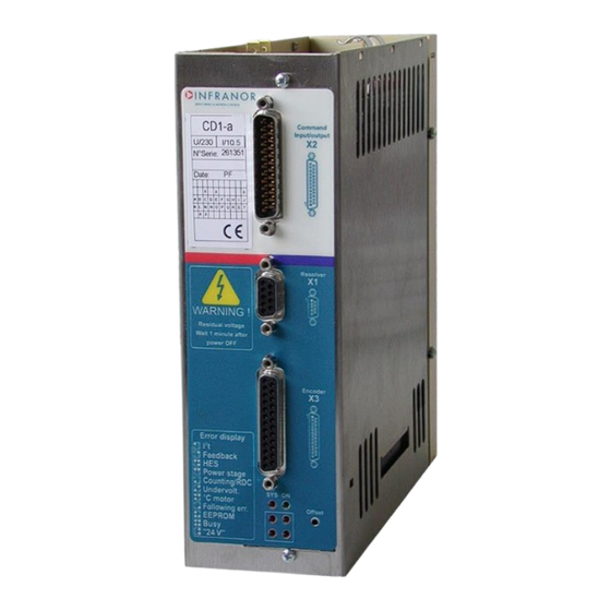
Infranor XtrapulsCD1-a Series Manual (60 pages)
Digital drive for AC sinusoidal brushless motors
Brand:
Infranor
| Category:
DC Drives
| Size: 2.18 MB
Table of Contents
Content
3
Table of Contents
3
Chapter 1 - General Description
6
1- Introduction
6
Description / Compliance with the Standards
6
General Description
6
Reference to the Standards: "Ce" Certification
7
Reference to the Standards: "Ul" Listing
7
Other Documents
7
Chapter 2 - Specifications
8
Technical Specifications
8
XTRAPULS CD1-A-230/I DRIVE
8
XTRAPULS CD1-A-400/I DRIVE
8
COMMON SPECIFICATIONS to both DRIVE VERSIONS XTRAPULS CD1-A-230/I and XTRAPULS CD1-A-400/I
9
Block Diagram
12
Main Protections
13
Stored Protections
13
Dimensions
14
XTRAPULS CD1-A-230/I
14
XTRAPULS CD1-A-400/1,8 to 7,2 a
14
XTRAPULS CD1-A-400/14
14
XTRAPULS CD1-A-400/30/45/70 and 90 a
14
BRAKING RESISTORS Dp 100/100, Dp 200/100, Dp 50/200, Dp 33/280 and Dp 16.5/560
15
Fastening
16
XTRAPULS CD1-A-230/I
16
XTRAPULS CD1-A-400/1.8 to 7.2 a
16
XTRAPULS CD1-A-400/14
16
XTRAPULS CD1-A-400/30/45/70 and 90 a
16
Multiaxes Cabinet Mounting
17
XTRAPULS CD1-A-230/I
17
XTRAPULS CD1-A-400/1.8 to 7.2 a
17
XTRAPULS CD1-A-400/14
17
XTRAPULS CD1-A-400/30/45/70 and 90 a
17
Chapter 3 - Inputs-Outputs
18
Connectors Location
18
Drive Connectors
18
X1: Resolver Connector (Subd 9 Pins Female )
18
X2: Command Connector, Logic Inputs-Outputs and Encoder (Subd 25 Pins Male )
19
SPECIFICATION of the ANALOG INPUTS: CV+, CV-, Ilim
20
Specification of the Logic Optocoupled Inputs: Enable, Fcp, Fcn, Reset, Cvo, CI
20
Specification of the "Aok" Relay Output
20
Specification of the Encoder Outputs
21
Specification of the Analog Output
21
X3 Encoder Input
21
X3 CONNECTOR for TTL INCREMENTAL ENCODER & HES INPUT (Sub D 25 Pins Female)
21
X3 CONNECTOR for Sincos INCREMENTAL ENCODER & HES INPUT (Sub D 25 Pins Female)
22
X3 CONNECTOR for ABSOLUTE SINGLE-TURN Sincos ENCODER (Sub D 25 Pins Female)
23
X3 CONNECTOR for STEPPER MOTOR EMULATION (Sub D 25 Pins Female)
24
X5 SERIAL LINK (Sub D 9 Pins Male)
25
X8: Auxiliary Supply Connector
25
7- X9 Power Connector: Mains, Motor, Braking Resistor (Cd1- a -230 V and 400
25
Chapter 4 - Connections
26
Connection Diagrams
26
XTRAPULS CD1-A-230/I DRIVE
26
XTRAPULS CD1-A-400/I DRIVE
27
Serial Link Connection
27
Connection of a Backup Battery for the 24 VDC Auxiliary Supply
28
Connection Example for a Multiaxis Application
28
Wiring
29
Ground Wiring and Leakage Current
29
Connectors Shield Connection
30
CONNECTION VIEW of XTRAPULS CD1-A-400/30 to 90 a
31
Motor, Resolver and Encoder Cables
31
Input Command and Serial Link Cables
32
Connection Cables of the Braking Resistor
32
Requirements of Compliance with the Ul Standards
33
Connection by Means of Faston Socket
33
24 V Supply
33
Power Supply and Ul Fuse Ratings
33
XTRAPULS CD1-A-230/I DRIVE: CONNECTION DIAGRAM with PROTECTIONS by "UL" FUSES
34
XTRAPULS CD1-A-400/I DRIVE: CONNECTION DIAGRAM with PROTECTIONS by "UL" FUSES
35
Connection Example for a Ul Compliant Multiaxis Application
36
Chapter 5 - Parameter Setting
37
Chapter 6 - Commissioning
38
Drive Standard Configuration
38
First Powering of the Xtrapuls Cd1- Adrive
38
Very Important
38
Switch on the 24 VDC Supply
38
SWITCH on the 230 VAC or 400 VAC SUPPLY (According to the Drive Type)
38
Drive Commissioning and Adjustment
39
Communication Via the Serial Link
39
Sensor Feedback Configuration
39
Drive Adjustment
39
Parameters Adjustment to a Linear Motor
40
Speed Loop Adjustment with Vertical Load
41
Drive Parameters Saving
41
Motor Phasing at Power up
41
Application of the Stepper Motor Emulation
42
Software Gearing Application
42
Chapter 7 - Troubleshooting
44
Faults
44
System Fault
44
Busy" Fault
44
Eeprom" Fault
44
C Motor" Fault
44
UNDERVOLT" FAULT (Non Stored)
44
Power Stage" Fault
45
Feedback" Fault in the Resolver Feedback Configuration
45
Rdc " Fault in the Resolver Feedback Configuration
45
Feedback" Fault in the Encoder Feedback Configuration
46
Counting" Fault in the Encoder Feedback Configuration
46
Hes" Fault
47
I T" Fault
48
Following Error
48
Operating Problems
48
Motor Does Not Move
48
Motor Supplied, but Not Torque
48
Shaft Locked, Erratic Oscillations or Rotation at Maximum Speed
48
Discontinuous Motor Rotation with Zero Torque Positions
49
Motor Drift with Analog Input Command at Zero Speed
49
Loud Crackling Noise in the Motor at Standstill
49
Loud Noise in the Motor at Standstill and When Running
49
Position Control Not Possible with the Nc
49
Service and Maintenance
49
Chapter 8 - Appendix
50
Hardware Adjustments
50
Adjustment to Various Resolver Types
51
Adjustment to Various Motor Types
51
Motor Thermal Sensor
51
I T PROTECTION
52
Encoder Counting Protection
53
Position Following Protection
54
Use of the "Limit Switch" Inputs
54
Use of the "Cv0" Input
55
Use of the "Aok" Output
55
Use of the "Reset" Input
55
Use of the "Enable" Input
55
Use of the "Brake" Output
55
Incremental Encoder Outputs
56
Use of the "External Current Limitation" Input
56
Servo Controller Structure
57
Drive Addressing Via Rs-232
58
Drive Addressing Via Rs-422
59
Cogging Torque Compensation
59
System of Power Feedback Via a Braking Resistor
60
Ordering Code
60
Advertisement
Advertisement
Related Products
Infranor XtrapulsCD1-k
Infranor XtrapulsCD1-a-230/4.5
Infranor XtrapulsCD1-a-230/2.25
Infranor XtrapulsCD1-a-230/7.5
Infranor XtrapulsCD1-a-230/10.5
Infranor XtrapulsCD1-a-230/16.5
Infranor XtrapulsCD1-EM-400/70
Infranor XtrapulsCD1-EM-400/90
Infranor XtrapulsGem
Infranor XtrapulsCD1-pm
Infranor Categories
DC Drives
Amplifier
Controller
Servo Drives
Control Unit
More Infranor Manuals
Login
Sign In
OR
Sign in with Facebook
Sign in with Google
Upload manual
Upload from disk
Upload from URL