Sign In
Upload
Manuals
Brands
IEI Technology Manuals
Desktop
SBOX-100-QM87i
IEI Technology SBOX-100-QM87i Computer Manuals
Manuals and User Guides for IEI Technology SBOX-100-QM87i Computer. We have
1
IEI Technology SBOX-100-QM87i Computer manual available for free PDF download: User Manual
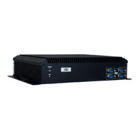
IEI Technology SBOX-100-QM87i User Manual (115 pages)
fanless marine computer with intel core i5-4400e dual-core cpu, intel qm87 express chipset, gbe lan, hdmi, dvi-d, vga, can bus, cfast slot, rs-232/422/485, usb 2.0, usb 3.0, iris-2400, rohs compliant
Brand:
IEI Technology
| Category:
Desktop
| Size: 4 MB
Table of Contents
Table of Contents
4
User Manual
1
1 Introduction
13
Overview
14
Features
14
Figure 1-1: SBOX-100-Qm87I Fanless Marine Computer
14
Front Panel
15
Figure 1-2: Front Panel
15
Rear Panel
16
Figure 1-3: Rear Panel
16
Technical Specifications
17
Table 1-1: Technical Specifications
18
Dimensions
19
Figure 1-4: SBOX-100-Qm87I Dimensions (MM)
19
2 Unpacking
20
Anti-Static Precautions
21
Unpacking Precautions
21
Unpacking Checklist
22
Table 2-1: Package List Contents
23
3 Installation
24
Installation Precautions
25
High Surface Temperature
25
Cfast Card Installation
26
Figure 3-1: Cfast Slot Cover Retention Screw
26
Figure 3-2: Cfast Card Installation
26
Hdd Installation
27
Figure 3-3: Bottom Cover Retention Screws
27
Figure 3-4: HDD Bracket Retention Screws
27
Figure 3-5: Inserting the HDD
28
Figure 3-6: Installing the HDD
28
At/Atx Mode Selection
29
Mounting the System
29
Figure 3-7: AT/ATX Mode Selection
29
Figure 3-8: Mounting Brackets
29
Serial Device Connection
30
Figure 3-9: Serial Port Locations
30
Serial Port (COM1)
31
RS-232/422/485 Serial Port (COM2-COM5)
31
Table 3-1: RS-232 Serial Port (COM1) Pinouts
31
Table 3-2: RS-232/422/485 Serial Port Pinouts
31
Can Bus Connection and Configuration
32
Table 3-3: CAN Bus Connector Pinouts
32
Powering on the System
33
Figure 3-10: CAN Bus Connector
32
Table 3-4: CAN Bus Jumper Settings
33
Clear Cmos
34
Driver Installation
34
Figure 3-11: CAN Bus Jumper Locations
33
Figure 3-12: Power Input Connector Pinouts
33
Figure 3-13: Power Connector and Power Button
34
Figure 3-14: Clear CMOS Button Location
34
Ipmi Setup Procedure
35
Managed System Hardware Setup
35
Using the IEI Iman Web GUI
36
Figure 3-15: IEI Iman Web Address
36
Figure 3-16: IEI Iman Web GUI
37
4 Bios Setup
38
Introduction
39
Starting Setup
39
Using Setup
39
BIOS Menu Bar
40
Getting Help
40
Table 4-1: BIOS Navigation Keys
40
Main
41
Advanced
42
System Date [XX/XX/XX]
42
System Time [XX:XX:XX]
42
ACPI Settings
43
ACPI Sleep State [S1 Only (CPU Stop Clock)]
43
RTC Wake Settings
44
Wake System with Fixed Time [Disabled]
44
Trusted Computing
45
CPU Configuration
46
Active Processor Cores [All]
46
Hyper-Threading [Disabled]
46
Security Device Support [Disable]
46
EIST [Enabled]
48
Intel TXT (LT) Support [Disabled]
48
SATA Configuration
49
Intel Virtualization Technology [Disabled]
48
SATA Controller(S) [Enabled]
49
SATA Mode Selection [IDE]
49
Intel Rapid Start Technology
50
Intel(R) Rapid Start Technology [Disabled]
50
AMT Configuration
51
Intel AMT [Enabled]
51
Un-Configure ME [Disabled]
51
USB Configuration
52
Legacy USB Support [Enabled]
52
Iwdd H/W Monitor
53
USB Devices
52
H/W Monitor
53
F81866 Super IO Configuration
54
Serial Port N Configuration
55
Serial Port Mode [RS485]
55
Serial Port Console Redirection
60
BIOS Menu 14: Serial Port Console Redirection
61
IEI Feature
62
Auto Recovery Function [Disabled]
62
Chipset
63
PCH-IO Configuration
63
Azalia (HD Audio) [Enabled]
63
Serial IRQ Mode [Continuous]
63
Power Saving Function(ERP) [Disabled]
63
System Agent (SA) Configuration
65
Graphics Configuration
66
Primary Display [Auto]
66
DVMT Pre-Allocated [256M]
66
DVMT Total Gfx Mem [256M]
67
Primary IGFX Boot Display [VBIOS Default]
67
Memory Configuration
68
Boot
68
Bootup Numlock State [On]
69
Quiet Boot [Enabled]
69
Option ROM Messages [Force BIOS]
69
Security
70
Launch PXE Oprom [Disabled]
70
UEFI Boot [Disabled]
70
Administrator Password
70
Save & Exit
71
User Password
71
Save Changes and Reset
71
Discard Changes and Reset
71
Restore Defaults
71
Save as User Defaults
71
Restore User Defaults
71
BIOS Menu 23: Save & Exit
71
Server Management
72
System Event Log
73
SEL Components [Enabled]
73
Erase SEL [No]
73
When SEL Is Full [Do Nothing]
73
Log EFI Status Codes [Both]
73
BMC Network Configuration
75
Configuration Address Source [Unspecified]
75
Console Redirection [Enabled]
61
5 Maintenance
76
System Maintenance Overview
77
So-DIMM Replacement Procedure
77
Figure 5-1: Bottom Cover Retention Screws
78
Figure 5-2: SO-DIMM Locations
78
Figure 5-3: SO-DIMM Installation
79
6 Interface Connectors
80
Peripheral Interface Connectors
81
Figure 6-1: Main Board Layout Diagram (Front Side)
81
Figure 6-2: Main Board Layout Diagram (Solder Side)
82
Internal Peripheral Connectors
83
Audio Connector (AUDIO1)
84
Battery Connector (BAT1)
84
Chassis Intrusion Connector (CHASSIS1)
84
Table 6-1: Peripheral Interface Connectors
84
Table 6-2: Audio Connector (AUDIO1) Pinouts
84
Table 6-3: Battery Connector (BAT1) Pinouts
84
Table 6-4: Chassis Intrusion Connector (CHASSIS1) Pinouts
84
Digital I/O Connector (DIO1)
85
EC Debug Connector (LPT_DB1)
85
Fan Connector (CPU_FAN1)
85
Table 6-5: Digital I/O Connector (DIO1) Pinouts
85
Table 6-6: EC Debug Connector (LPT_DB1) Pinouts
85
Table 6-7: Fan Connector (CPU_FAN1) Pinouts
85
Front Panel Connector (F_PANEL1)
86
IPMI LED Connector (IPMI_LED1)
86
LAN Active LED Connector (LAN_ACT_LED1)
86
Pcie Mini Slots (MINI-PCIE1, MINI-PCIE2)
86
Table 6-8: Front Panel Connector (F_PANEL1) Pinouts
86
Table 6-9: IPMI LED Connector (IPMI_LED1) Pinouts
86
Power Connector (PWR1)
87
Table 6-10: LAN Active LED Connector (LAN_ACT_LED1)
86
Table 6-11: Pcie Mini Slots (MINI-PCIE1, MINI-PCIE2) Pinouts
87
Table 6-12: Power Connector (PWR1) Pinouts
87
Power Button Connector (PWR_BTN1)
88
PS_ON Connector (PS_ON1)
88
RS-232/422/485 Connector (COM2, COM3, COM4, COM5)
88
SATA Connector (S_ATA1)
88
Table 6-13: Power Button Connector (PWR_BTN1) Pinouts
88
Table 6-14: PS_ON Connector (PS_ON1) Pinouts
88
Table 6-15: RS-232/422/485 Connectors (COM2, COM3, COM4, COM5)
88
SATA Connector (S_ATA2)
89
SATA Power Connector (SATA_PWR1)
89
Table 6-16: SATA Connector (S_ATA1) Pinouts
89
Table 6-17: SATA Connector (S_ATA2) Pinouts
89
Table 6-18: SATA Power Connector (SATA_PWR1) Pinouts
89
SATA Power Connector (SATA_PWR2)
90
Smbus Connector, EC (SMB1)
90
SPI Flash Connector (SPI1)
90
Table 6-19: SATA Power Connector (SATA_PWR2) Pinouts
90
Table 6-20: Smbus Connector, EC (SMB1)
90
Table 6-21: SPI Flash Connector (SPI1) Pinouts
90
External Interface Panel Connectors
91
SPI Flash Connector, EC (CN2)
91
Table 6-22: SPI Flash Connector, EC (CN2)
91
Table 6-23: TPM Connector (TPM1) Pinouts
91
CAN Bus Connector (CAN1)
92
DVI Connector (DVI)
92
Table 6-25: CAN Bus Connector (CAN1) Pinouts
92
Table 6-26: DVI Connector (DVI) Pinouts
92
VGA Connector (VGA1)
93
HDMI Connector (HDMI1)
93
Table 6-24: Rear Panel Connectors
92
Table 6-27: VGA Connector (VGA1) Pinouts
93
Table 6-28: HDMI Connector (HDMI1) Pinouts
93
Gbe Connectors (LAN1/2-CN1)
94
Serial Port (COM1)
94
USB 2.0 Connectors (USB1)
94
Table 6-29: RJ-45 Gbe Connector (LAN1/2-CN1) Pinouts
94
Table 6-30: RS-232 Serial Port (COM1) Pinouts
94
Table 6-31: USB 2.0 Connector (USB1) Pinouts
94
USB 3.0 Connectors (USB3_CN1)
95
Table 6-32: USB 3.0 Connector (USB3_CN1) Pinouts
95
TPM Connector (TPM1)
91
A Regulatory Compliance
96
B Safety Precautions
101
Safety Precautions
102
General Safety Precautions
102
Anti-Static Precautions
103
Product Disposal
104
Maintenance and Cleaning Precautions
104
Maintenance and Cleaning
104
Cleaning Tools
105
CBIOS Menu Options
106
C.1 BIOS Configuration Options
107
Bios Configuration Options
107
C.1 Bios C Onfiguration O Ptions
107
D Watchdog Timer
109
Example Program
111
E Hazardous Materials Disclosure
112
Hazardous Material Disclosure Table for IPB Products Certified as Rohs Compliant under 2002/95/EC Without Mercury
113
E.1 H Azardous M Aterial D Isclosure T Able for Ipb P Roducts C Ertified as R O Hs C Ompliant U Nder 2002/95/Ec W Ithout M Ercury
113
Advertisement
Advertisement
Related Products
IEI Technology SAILORPC-12A
IEI Technology SEG-1
IEI Technology SEG-M
IEI Technology SRM-150A
IEI Technology SPCIE-C2260-i2
IEI Technology S19A-QM87i-i
IEI Technology S24A-QM87i-i
IEI Technology S24M
IEI Technology SPCIE-C236-R10
IEI Technology STRD-01
IEI Technology Categories
Motherboard
Touch Panel
Computer Hardware
Single board computers
Desktop
More IEI Technology Manuals
Login
Sign In
OR
Sign in with Facebook
Sign in with Google
Upload manual
Upload from disk
Upload from URL