Sign In
Upload
Manuals
Brands
IEI Technology Manuals
Desktop
SAILORPC-12A
IEI Technology SAILORPC-12A Manuals
Manuals and User Guides for IEI Technology SAILORPC-12A. We have
1
IEI Technology SAILORPC-12A manual available for free PDF download: User Manual
IEI Technology SAILORPC-12A User Manual (110 pages)
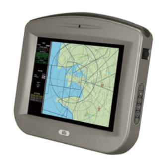
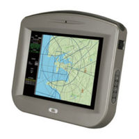
waterproof panel pc 1.6GHz intel atom cpu, 802.11b/g/n wireless, gigabit ethernet, usb, rs-232, rs-232/422/485, can bus, rohs compliant, ip 67
Brand:
IEI Technology
| Category:
Desktop
| Size: 1.9 MB
Table of Contents
Table of Contents
4
User Manual
1
1 Introduction
11
Overview
12
Features
13
Front Panel
13
Rear Panel
13
Figure 1-2: Front Panel
13
Connectors
14
Figure 1-3: Rear Panel
14
Technical Specifications
15
Figure 1-1: SAILORPC-12A
15
Figure 1-4: Connectors
15
Table 1-1: Technical Specifications
16
Dimensions
17
Figure 1-5: Dimensions (Units in MM)
17
2 Unpacking
18
Unpack the Panel Pc
19
Packing List
20
Table 2-1: Packing List
21
Table 2-2: Packing List
22
3 Installation
23
Tighten the Pressure Release Screw
24
Figure 3-1: Pressure Release Screw
24
Hard Drive Installation
25
Figure 3-2: Aluminum Back Cover Retention Screws
25
Compactflash® Installation
26
Figure 3-3: HDD Installation
26
Figure 3-4: Compactflash® Install
26
Jumper Settings
27
Reset CMOS
27
AT/ATX Power
27
Table 3-1: Reset CMOS
27
COM2 RS-232/422/485 Selection
28
Table 3-2: AT/ATX Power
28
Table 3-3: COM2 RS-232/422/485 Setup
28
Table 3-4: COM2 RS-232/422/485 Setup
28
Panel Resolution
29
Table 3-5: COM2 Serial Port Pinouts
29
Table 3-6: Panel Resolution
29
I/O Connector Pinouts
30
LAN Connector
30
Figure 3-5: Connectors
30
Figure 3-6: LAN Port
30
Table 3-7: LAN Port
31
Table 3-8: Serial Port
31
CAN & Audio Connector
32
Figure 3-7: Serial Port
31
Serial Port Connector
31
Table 3-9: CAN & Audio Port
32
USB Port Connector
32
Figure 3-8: CAN & Audio Port
32
Figure 3-9: USB Port
32
Table 3-10: Serial Port
33
Table 3-11: Power Connector
33
Bottom Panel Connectors
34
Figure 3-10: Power Connector
33
Power Connector
33
Figure 3-11: Connectors
34
M12 Connection
35
LAN Connection Cable
35
Figure 3-12: M12 Connector
35
Serial Device Cable
36
Figure 3-13: LAN Connection
36
USB Device Cable
37
Figure 3-14: Serial Device Connector
37
Figure 3-15: USB Device Connection
37
Mounting the System
34
Driver Installation
38
Power Connection
38
4 Osd
39
Osd Buttons
40
Figure 4-1: OSD Buttons
40
Osd Software
41
Figure 4-2: OSD Software
41
Figure 4-3: OSD Software
41
5 Bios Setup
42
Introduction
43
Starting Setup
43
Using Setup
43
Getting Help
44
Unable to Reboot after Configuration Changes
44
BIOS Menu Bar
44
Table 5-1: BIOS Navigation Keys
44
BIOS Menu 1: Main
45
System Overview
45
Advanced
46
Main
45
BIOS Menu 2: Advanced
46
System Time [XX:XX:XX]
46
System Date [XX/XX/XX]
46
CPU Configuration
47
BIOS Menu 3: CPU Configuration
47
IDE Configuration
48
BIOS Menu 4: IDE Configuration
48
ATA/IDE Configuration [Compatible]
48
Legacy IDE Channels [SATA Pri, PATA Sec]
48
IDE Master, IDE Slave
49
BIOS Menu 5: IDE Master and IDE Slave Configuration
49
Configure SATA as [IDE]
49
Auto-Detected Drive Parameters
49
Type [Auto]
50
Lba/Large Mode [Auto]
51
Block (Multi Sector Transfer) [Auto]
51
PIO Mode [Auto]
51
DMA Mode [Auto]
52
Auto]
53
32Bit Data Transfer [Enabled]
53
Super IO Configuration
54
BIOS Menu 6: Super IO Configuration
54
Serial Port1 Address [3F8/IRQ4]
54
Serial Port1 Mode [Normal]
54
Serial Port3 Address [3E8]
55
Serial Port3 IRQ [11]
55
Select RS232 or RS422/RS485 [RS/232]
55
Serial Port4 Address [2E8]
55
Serial Port4 IRQ [11]
55
Hardware Health Configuration
56
BIOS Menu 7: Hardware Health Configuration
56
Serial Port5 Address [2F0]
56
Serial Port5 IRQ [10]
56
Mode Setting [Full on Mode]
57
Temp. Limit of off [000]
57
Temp. Limit of Start [020]
57
Start PWM [070]
58
Slope PWM [1 PWM]
58
CPU Fan PWM Control [070]
58
Monitored Values
58
Power Configuration
59
BIOS Menu 8: APM Configuration
59
ACPI Settings
60
BIOS Menu 9: ACPI Settings
60
Suspend Mode [S1(POS)]
60
APM Configuration
61
BIOS Menu 10: APM Configuration
61
Restore on AC Power Loss [Last State]
61
Power Button Mode [On/Off]
61
Resume on Keyboard/Mouse [Disabled]
62
Resume on Ring [Disabled]
62
Resume on PCI-Express WAKE# [Enabled]
62
Resume on RTC Alarm [Disabled]
62
Remote Access Configuration
63
BIOS Menu 11: Remote Access Configuration
63
Remote Access [Disabled]
63
Serial Port Number [COM1]
64
Base Address, IRQ [2F8H,3]
64
Serial Port Mode [115200 8,N,1]
64
Flow Control [None]
65
Redirection after BIOS POST [Always]
65
Terminal Type [ANSI]
65
VT-UTF8 Combo Key Support [Disabled]
66
Sredir Memory Display Delay [Disabled]
66
USB Configuration
67
BIOS Menu 12: USB Configuration
67
USB Devices Enabled
67
USB Function [Enabled]
67
USB 2.0 Controller [Enabled]
68
Legacy USB Support [Enabled]
68
USB2.0 Controller Mode [Hispeed]
68
USB Mass Storage Device Configuration
69
BIOS Menu 13: USB Mass Storage Device Configuration
69
USB Mass Storage Reset Delay [20 Sec]
69
Device
69
Pci/Pnp
70
Emulation Type [Auto]
70
BIOS Menu 14: Pci/Pnp Configuration
71
IRQ# [Available]
71
DMA Channel# [Available]
72
Reserved Memory Size [Disabled]
72
Boot
73
Boot Settings Configuration
73
BIOS Menu 15: Boot
73
BIOS Menu 16: Boot Settings Configuration
73
Quick Boot [Enabled]
74
Quiet Boot [Enabled]
74
Addon ROM Display Mode [Force BIOS]
74
Bootup Num-Lock [On]
74
Boot from LAN Support [Disabled]
75
Spread Spectrum Mode [Disabled]
75
Boot Device Priority
76
BIOS Menu 17: Boot Device Priority Settings
76
Hard Disk Drives
77
Removable Drives
77
BIOS Menu 18: Hard Disk Drives
77
BIOS Menu 19: Removable Drives
77
CD/DVD Drives
78
BIOS Menu 20: CD/DVD Drives
78
Security
79
BIOS Menu 21: Security
79
Change Supervisor Password
79
Change User Password
79
Chipset
80
BIOS Menu 22: Chipset
80
Northbridge Configuration
81
BIOS Menu 23:Northbridge Chipset Configuration
81
Memory Hole [Disabled]
81
Internal Graphics Mode Select [Enable, 8 MB]
81
DVMT Mode Select [DVMT Mode]
82
DVMT/FIXED Memory [128 MB]
82
Boot Display Device [Auto]
82
Secondary Display Device [Auto]
83
LFP Panel Type
83
LFP Current Jumper Setting
83
Southbridge Configuration
84
Exit
84
BIOS Menu 24:Southbridge Chipset Configuration
84
Audio Controller [Auto]
84
BIOS Menu 25:Exit
85
Save Changes and Exit
85
Discard Changes and Exit
85
Discard Changes
85
Load Optimal Defaults
85
Load Failsafe Defaults
85
6 System Maintenance
86
System Maintenance Introduction
87
Motherboard Replacement
87
Cover Removal
87
Memory Module Replacement
88
Figure 6-1: Back Cover Retention Screws
88
Hard Drive and Compactflash® Replacement
89
Cover Replacement
89
Figure 6-2: DDR SO-DIMM Module Installation
89
Figure 6-3: Rubber Seal
90
Figure 6-4: Thermal Pads
90
Figure 6-5: Rear Cover Screws
91
A Safety Precautions
92
Safety Precautions
93
General Safety Precautions
93
Anti-Static Precautions
94
Maintenance and Cleaning Precautions
94
Maintenance and Cleaning
94
Cleaning Tools
95
BBIOS Options
96
Appendix B
97
C Terminology
100
D Watchdog Timer
104
Example Program
106
E Hazardous Materials Disclosure
107
Hazardous Materials Disclosure Table for IPB Products Certified as Rohs Compliant under 2002/95/EC Without Mercury
108
Advertisement
Advertisement
Related Products
IEI Technology SBOX-100-QM87i
IEI Technology SAGP-648E
IEI Technology SEG-1
IEI Technology SRM-KIT Series
IEI Technology SRM-150
IEI Technology S24A-QM87i-i
IEI Technology S24M
IEI Technology SPCIE-C236
IEI Technology SPCIE-C236-R10
IEI Technology SPCIE-C2260-i2-R10
IEI Technology Categories
Motherboard
Touch Panel
Computer Hardware
Single board computers
Desktop
More IEI Technology Manuals
Login
Sign In
OR
Sign in with Facebook
Sign in with Google
Upload manual
Upload from disk
Upload from URL