Sign In
Upload
Manuals
Brands
IEI Technology Manuals
Touch Panel
S24A-QM87i-i
IEI Technology S24A-QM87i-i Manuals
Manuals and User Guides for IEI Technology S24A-QM87i-i. We have
1
IEI Technology S24A-QM87i-i manual available for free PDF download: User Manual
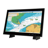
IEI Technology S24A-QM87i-i User Manual (137 pages)
MARINE PANEL PC
Brand:
IEI Technology
| Category:
Touch Panel
| Size: 5 MB
Table of Contents
Table of Contents
4
1 Introduction
13
Overview
14
Features
14
Figure 1-1: S19A-Qm87I-I5 Marine Panel PC
14
Front Panel
15
Figure 1-2: S24A-Qm87I-I5 Front Panel
15
Display Control Buttons
16
Top Panel
16
Figure 1-3: Display Control Buttons
16
Figure 1-4: Top Panel
16
Bottom Panel
17
Rear Panel
18
Figure 1-5: Bottom Panel
18
Figure 1-6: S19A-Qm87I-I5 Rear Panel
18
Technical Specifications
19
Table 1-1: Technical Specifications
21
Dimensions
22
Figure 1-7: S19A-Qm87I-I5 Dimensions (MM)
22
Figure 1-8: S24A-Qm87I-I5 Dimensions (MM)
23
2 Unpacking
24
Anti-Static Precautions
25
Unpacking Precautions
25
Unpacking Checklist
26
Table 2-1: Package List
26
Optional Items
27
Table 2-2: Optional Items
27
3 Installation
28
Installation Precautions
29
High Surface Temperature
29
Cfast Card Installation
30
Figure 3-1: Cfast Slot Cover Retention Screw
30
Figure 3-2: Cfast Card Installation
30
Hdd Installation
31
Figure 3-3: SBOX Computer Retention Screws
31
Figure 3-4: Bottom Cover Retention Screws
32
Figure 3-5: HDD Bracket Retention Screws
32
Figure 3-6: Inserting the HDD
33
Figure 3-7: Installing the HDD
33
At/Atx Mode Selection
34
Mounting the System
34
Figure 3-8: AT/ATX Mode Selection
34
Panel Mounting
35
Figure 3-9: S19A-Qm87I-I5 Cutout Dimensions
35
Figure 3-10: S24A-Qm87I-I5 Cutout Dimensions
35
Figure 3-11: S19A-Qm87I-I5 Panel Mounting Hole Covers
36
Figure 3-12: S24A-Qm87I-I5 Panel Mounting Hole Covers
36
Stand Mounting
37
Figure 3-13: Tighten the Panel Mounting Clamp Screws
37
Figure 3-14: S19A-Qm87I-I5 Stand Mounting Screw Holes
38
Figure 3-15: S24A-Qm87I-I5 Stand Mounting Screw Holes
38
Ceiling Mounting
39
Figure 3-16: Installing Stand
39
Figure 3-17: Stand Mounting Method 2
39
Figure 3-18: Locations of Bracket Screw Holes for S19A-Qm87I
40
Figure 3-19: Locations of Bracket Screw Holes for S24A-Qm87I
40
Figure 3-20: Ceiling Mounting Bracket Adjustment
41
Figure 3-21: Knockout Holes for Ceiling Mounting Brackets
41
Figure 3-22: Installing Ceiling Mounting Bracket (One Side)
42
Figure 3-24: Alternative of Ceiling Mounting Brackets
43
Serial Device Connection
44
Figure 3-23: Ceiling Mounting
43
Figure 3-25: Serial Port Locations
44
Serial Port (COM1)
45
RS-232/422/485 Serial Port (COM2-COM5)
45
Table 3-1: RS-232 Serial Port (COM1) Pinouts
45
Table 3-2: RS-232/422/485 Serial Port Pinouts
45
Can Bus Connection and Configuration
46
Figure 3-26: CAN Bus Connector
46
Table 3-3: CAN Bus Connector Pinouts
46
Powering on the System
47
Figure 3-27: CAN Bus Jumper Locations
47
Figure 3-28: Power Input Connector Pinouts
47
Table 3-4: CAN Bus Jumper Settings
47
Clear Cmos
48
Figure 3-29: Power Connector and Power Button
48
Figure 3-30: Clear CMOS Button Location
48
Driver Installation
49
Ipmi Setup Procedure
50
Managed System Hardware Setup
50
Using the IEI Iman Web GUI
50
Figure 3-31: IEI Iman Web Address
51
Figure 3-32: IEI Iman Web GUI
51
4 On-Screen-Display (Osd) Controls
53
User Mode Osd Structure
54
OSD Buttons
54
Table 4-1: OSD Control Buttons
54
OSD Menu Structure
55
Figure 4-1: OSD Button Locations
54
Table 4-2: OSD Menus
55
Using the Osd
56
Image Menu
56
Figure 4-2: Image Menu
56
System Menu
57
Figure 4-3: System Menu
57
5 Bios Setup
59
Introduction
60
Starting Setup
60
Using Setup
60
BIOS Menu Bar
61
Getting Help
61
Table 5-1: BIOS Navigation Keys
61
Main
62
Advanced
63
System Date [XX/XX/XX]
63
System Time [XX:XX:XX]
63
ACPI Settings
64
ACPI Sleep State [S1 Only (CPU Stop Clock)]
64
RTC Wake Settings
65
Wake System with Fixed Time [Disabled]
65
Trusted Computing
66
CPU Configuration
67
Security Device Support [Disable]
67
Active Processor Cores [All]
68
Hyper-Threading [Disabled]
68
EIST [Enabled]
69
Intel TXT (LT) Support [Disabled]
69
SATA Configuration
70
Intel Virtualization Technology [Disabled]
69
SATA Controller(S) [Enabled]
70
SATA Mode Selection [IDE]
70
Intel Rapid Start Technology
71
Intel(R) Rapid Start Technology [Disabled]
71
AMT Configuration
72
Intel AMT [Enabled]
72
Un-Configure ME [Disabled]
72
USB Configuration
73
Legacy USB Support [Enabled]
73
Iwdd H/W Monitor
74
USB Devices
73
H/W Monitor
74
F81866 Super IO Configuration
75
Serial Port N Configuration
76
Change Settings [Auto]
76
Serial Port [Enabled]
76
Change Settings [Auto]
77
Serial Port [Enabled]
77
Change Settings [Auto]
78
Serial Port Mode [RS485]
78
Serial Port [Enabled]
78
Change Settings [Auto]
79
Serial Port Mode [RS485]
79
Serial Port [Enabled]
79
Change Settings [Auto]
80
Serial Port Console Redirection
81
Serial Port Mode [RS485]
80
Serial Port [Enabled]
80
Serial Port Mode [RS485]
81
BIOS Menu 14: Serial Port Console Redirection
82
IEI Feature
83
Auto Recovery Function [Disabled]
83
Chipset
84
PCH-IO Configuration
84
Restore on AC Power Loss [Last State]
85
Azalia (HD Audio) [Enabled]
85
Serial IRQ Mode [Continuous]
85
Power Saving Function (ERP) [Disabled]
85
System Agent (SA) Configuration
86
VT-D [Disabled]
86
Graphics Configuration
87
Primary Display [Auto]
87
DVMT Pre-Allocated [256M]
87
DVMT Total Gfx Mem [256M]
88
Primary IGFX Boot Display [VBIOS Default]
88
Memory Configuration
89
Boot
89
Bootup Numlock State [On]
90
Quiet Boot [Enabled]
90
Option ROM Messages [Force BIOS]
90
Security
91
Launch PXE Oprom [Disabled]
91
UEFI Boot [Disabled]
91
Administrator Password
91
Save & Exit
92
User Password
92
Save Changes and Reset
92
Discard Changes and Reset
92
Restore Defaults
92
BIOS Menu 23: Save & Exit
92
Server Management
93
Save as User Defaults
93
Restore User Defaults
93
System Event Log
94
SEL Components [Enabled]
94
Erase SEL [No]
94
When SEL Is Full [Do Nothing]
95
Log EFI Status Codes [Both]
95
BMC Network Configuration
96
Configuration Address Source [Unspecified]
96
Console Redirection [Enabled]
82
6 Maintenance
97
System Maintenance Overview
98
So-DIMM Replacement Procedure
98
Figure 6-1: SBOX Computer Retention Screws
99
Figure 6-2: Bottom Cover Retention Screws
100
Figure 6-3: SO-DIMM Locations
100
Figure 6-4: SO-DIMM Installation
101
7 Interface Connectors
102
Peripheral Interface Connectors
103
Figure 7-1: Main Board Layout Diagram (Front Side)
103
Figure 7-2: Main Board Layout Diagram (Solder Side)
104
Internal Peripheral Connectors
105
Audio Connector (AUDIO1)
106
Battery Connector (BAT1)
106
Chassis Intrusion Connector (CHASSIS1)
106
Table 7-1: Peripheral Interface Connectors
106
Table 7-2: Audio Connector (AUDIO1) Pinouts
106
Table 7-3: Battery Connector (BAT1) Pinouts
106
Table 7-4: Chassis Intrusion Connector (CHASSIS1) Pinouts
106
Digital I/O Connector (DIO1)
107
EC Debug Connector (LPT_DB1)
107
Fan Connector (CPU_FAN1)
107
Table 7-5: Digital I/O Connector (DIO1) Pinouts
107
Table 7-6: EC Debug Connector (LPT_DB1) Pinouts
107
Table 7-7: Fan Connector (CPU_FAN1) Pinouts
107
Front Panel Connector (F_PANEL1)
108
IPMI LED Connector (IPMI_LED1)
108
LAN Active LED Connector (LAN_ACT_LED1)
108
Pcie Mini Slots (MINI-PCIE1, MINI-PCIE2)
108
Table 7-8: Front Panel Connector (F_PANEL1) Pinouts
108
Table 7-9: IPMI LED Connector (IPMI_LED1) Pinouts
108
Power Connector (PWR1)
109
Table 7-10: LAN Active LED Connector (LAN_ACT_LED1)
108
Table 7-11: Pcie Mini Slots (MINI-PCIE1, MINI-PCIE2) Pinouts
109
Table 7-12: Power Connector (PWR1) Pinouts
109
Power Button Connector (PWR_BTN1)
110
PS_ON Connector (PS_ON1)
110
RS-232/422/485 Connector (COM2, COM3, COM4, COM5)
110
SATA Connector (S_ATA1)
110
Table 7-13: Power Button Connector (PWR_BTN1) Pinouts
110
Table 7-14: PS_ON Connector (PS_ON1) Pinouts
110
Table 7-15: RS-232/422/485 Connectors (COM2, COM3, COM4, COM5)
110
SATA Connector (S_ATA2)
111
SATA Power Connector (SATA_PWR1)
111
Table 7-16: SATA Connector (S_ATA1) Pinouts
111
Table 7-17: SATA Connector (S_ATA2) Pinouts
111
Table 7-18: SATA Power Connector (SATA_PWR1) Pinouts
111
SATA Power Connector (SATA_PWR2)
112
Smbus Connector, EC (SMB1)
112
SPI Flash Connector (SPI1)
112
Table 7-19: SATA Power Connector (SATA_PWR2) Pinouts
112
Table 7-20: Smbus Connector, EC (SMB1)
112
Table 7-21: SPI Flash Connector (SPI1) Pinouts
112
External Interface Panel Connectors
113
SPI Flash Connector, EC (CN2)
113
Table 7-22: SPI Flash Connector, EC (CN2)
113
Table 7-23: TPM Connector (TPM1) Pinouts
113
CAN Bus Connector (CAN1)
114
DVI Connector (DVI)
114
Table 7-24: Rear Panel Connectors
114
Table 7-25: CAN Bus Connector (CAN1) Pinouts
114
Table 7-26: DVI Connector (DVI) Pinouts
114
VGA Connector (VGA1)
115
HDMI Connector (HDMI1)
115
Table 7-27: VGA Connector (VGA1) Pinouts
115
Table 7-28: HDMI Connector (HDMI1) Pinouts
115
Gbe Connectors (LAN1/2-CN1)
116
Serial Port (COM1)
116
USB 2.0 Connectors (USB1)
116
Table 7-29: RJ-45 Gbe Connector (LAN1/2-CN1) Pinouts
116
Table 7-30: RS-232 Serial Port (COM1) Pinouts
116
Table 7-31: USB 2.0 Connector (USB1) Pinouts
116
USB 3.0 Connectors (USB3_CN1)
117
Table 7-32: USB 3.0 Connector (USB3_CN1) Pinouts
117
TPM Connector (TPM1)
113
A Regulatory Compliance
118
B Safety Precautions
123
Safety Precautions
124
B.1 S Afety P Recautions
124
General Safety Precautions
124
Anti-Static Precautions
125
Product Disposal
126
Maintenance and Cleaning Precautions
126
Maintenance and Cleaning
126
Cleaning Tools
127
CBIOS Menu Options
128
C.1 BIOS Configuration Options
129
Bios Configuration Options
129
C.1 Bios C Onfiguration O Ptions
129
D Watchdog Timer
131
Example Program
133
E Hazardous Materials Disclosure
134
Hazardous Material Disclosure Table for IPB Products Certified as Rohs Compliant under 2002/95/EC Without Mercury
135
E.1 H Azardous M Aterial D Isclosure T Able for Ipb P Roducts C Ertified as R O Hs C Ompliant U Nder 2002/95/Ec W Ithout M Ercury
135
Advertisement
Advertisement
Related Products
IEI Technology S24A-QM87
IEI Technology S19A-QM87i-i
IEI Technology S19A-QM87
IEI Technology S19A/S24A-QM87i
IEI Technology S24M
IEI Technology S19M
IEI Technology SPCIE-C2260-i2-R10
IEI Technology SSW-iLW
IEI Technology SPCIE-C2260
IEI Technology SPCIE-3600AM2
IEI Technology Categories
Motherboard
Touch Panel
Computer Hardware
Single board computers
Desktop
More IEI Technology Manuals
Login
Sign In
OR
Sign in with Facebook
Sign in with Google
Upload manual
Upload from disk
Upload from URL