Sign In
Upload
Manuals
Brands
IEI Technology Manuals
PCI Card
PICOe-PV-D510
IEI Technology PICOe-PV-D510 Manuals
Manuals and User Guides for IEI Technology PICOe-PV-D510. We have
1
IEI Technology PICOe-PV-D510 manual available for free PDF download: User Manual
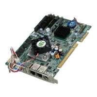
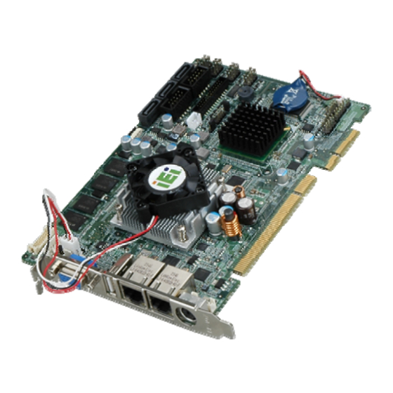
IEI Technology PICOe-PV-D510 User Manual (141 pages)
Half-size PCIe CPU Card with Intel Atom dual-core D510 CPU, 512 MB Onboard Memory, Dual Gigabit Ethernet, Seven USB, RS-232, Three SATA, CompactFlash Type II, VGA, LVDS, RoHS Compliant
Brand:
IEI Technology
| Category:
PCI Card
| Size: 4 MB
Table of Contents
Table of Contents
4
1 Introduction
13
Introduction
14
Connectors
15
Figure 1-2: Connectors
15
Figure 1-3: Picoe-PV-D510 Dimensions (MM)
16
Figure 1-4: Data Flow Block Diagram
17
Technical Specifications
18
Data Flow
17
Dimensions
16
Table 1-1: Technical Specifications
19
2 Unpacking
20
Anti-Static Precautions
21
Unpacking Precautions
21
Unpacking Checklist
21
Package Contents
22
Optional Items
23
3 Connectors
24
Figure 3-1: Connector and Jumper Locations [Front Side]
25
Table 3-2: Rear Panel Connectors
27
Table 3-1: Peripheral Interface Connectors
27
Figure 3-3: ATX Power Supply Enable Connector Location
28
Audio Connector (9-Pin)
29
Figure 3-4: Audio Connector Location (9-Pin)
29
Table 3-3: ATX Power Supply Enable Connector Pinouts
29
Table 3-4: Audio Connector Pinouts (9-Pin)
29
Backlight Inverter Connector
30
Table 3-5: Panel Backlight Connector Pinouts
30
Compactflash® Socket
31
Internal Peripheral Connectors
28
ATX Power Supply Enable Connector
28
Peripheral Interface Connectors
25
Picoe-PV-D510 Layout
25
Figure 3-2: Connector and Jumper Locations [Solder Side]
26
Peripheral Interface Connectors
26
External Interface Panel Connectors
27
Figure 3-5: Backlight Inverter Connector Pinout Locations
30
Figure 1-1: Picoe-PV-D510
31
Figure 3-6: CF Card Socket Location
31
Table 3-6: CF Card Socket Pinouts
32
Digital Input/Output (DIO) Connector
33
CPU Fan Connector (+12V, 4-Pin)
32
Figure 3-7: +12V Fan Connector Location
33
Figure 3-13: LVDS LCD Connector Pinout Location
39
Table 3-13: TFT LCD LVDS Port Connector Pinouts
39
Figure 3-15: Power Button Location
41
Power Button
41
SATA Drive Connectors
41
Table 3-14: Parallel Port Connector Pinouts
41
Figure 3-16: SATA Drive Connector Locations
42
Serial Port Connectors (COM 1 and COM 2)
42
Table 3-15: SATA Drive Connector Pinouts
42
Figure 3-17: COM Connector Pinout Locations
43
SPI Flash Connector
43
Table 3-16: COM Connector Pinouts
43
Figure 3-18: SPI Flash Connector
44
Table 3-17: SPI Flash Connector
44
USB Connectors (Internal)
44
External Peripheral Interface Connector Panel
45
Figure 3-19: USB Connector Pinout Locations
45
Figure 3-20: Picoe-PV-D510 External Peripheral Interface Connector
45
Table 3-18: USB Port Connector Pinouts
45
Figure 3-21: PS/2 Pinout and Configuration
46
Keyboard/Mouse Connector
46
LAN Connectors
46
Table 3-19: Keyboard Connector Pinouts
46
Table 3-20: LAN Pinouts
47
Table 3-21: RJ-45 Ethernet Connector Leds
47
USB Connectors
47
VGA Connector
48
Figure 3-14: Parallel Port Connector Location
40
Parallel Port Connector
40
Table 3-7: +12V Fan Connector Pinouts
33
Figure 3-8: DIO Connector Locations
34
Front Panel Connector (8-Pin)
34
Table 3-8: DIO Connector Connector Pinouts
34
Figure 3-9: Front Panel Connector Pinout Locations (8-Pin)
35
Infrared Interface Connector
35
Table 3-9: Front Panel Connector Pinouts (8-Pin)
35
Figure 3-10: Infrared Connector Pinout Locations
36
Keyboard/Mouse Connector
36
Table 3-10: Infrared Connector Pinouts
36
Figure 3-11: Keyboard/Mouse Connector Location
37
LPC Connector
37
Table 3-11: Keyboard/Mouse Connector Pinouts
37
Figure 3-12: LPC Connector Pinout Locations
38
LVDS LCD Connector
38
Table 3-12: LPC Connector Pinouts
38
Figure 3-22: RJ-45 Ethernet Connector
47
Table 3-22: USB Port Pinouts
48
Figure 3-23: VGA Connector
48
Table 3-23: VGA Connector Pinouts
49
4 Installation
50
Anti-Static Precautions
51
Installation Considerations
52
Installation Notices
52
Installation Checklist
53
Figure 4-1: SO-DIMM Installation
54
Figure 4-2: CF Card Installation
56
AT Power Select Jumper Settings
57
So-DIMM and Cf Card Installation
54
SO-DIMM Installation
54
Unpacking
54
CF Card Installation
55
Table 4-2: at Power Select Jumper Settings
57
Jumper Settings
56
Table 4-1: Jumpers
57
Figure 4-3: at Power Select Jumper Location
58
Figure 4-4: CF Card Setup Jumper Location
59
Figure 4-5: Clear CMOS Jumper
60
LVDS Voltage Selection
60
Table 4-4: Clear CMOS Jumper Settings
60
Figure 4-6: LVDS Voltage Selection Jumper Pinout Locations
61
Pcie Status Select
61
Table 4-5: LVDS Voltage Selection Jumper Settings
61
Airflow
62
Chassis Installation
62
Figure 4-7: Pcie Status Select Jumper Pinout Locations
62
Table 4-6: Pcie Status Select Jumper Settings
62
Backplane Installation
63
CPU Card Installation
63
Internal Peripheral Device Connections
63
Peripheral Device Cables
63
Channel Audio Kit Installation
64
SATA Drive Connection
65
Table 4-3: CF Card Setup Jumper Settings
58
Clear CMOS Jumper
59
CF Card Setup
58
Figure 4-8: 7.1 Channel Audio Kit
65
Figure 4-9: SATA Drive Cable Connection
66
Figure 4-10: SATA Power Drive Connection
67
Figure 4-11: Dual USB Cable Connection
68
Figure 4-12: LPT Cable Connection
69
Dual RS-232 Cable with Slot Bracket
70
Figure 4-13: Connect the LPT Device
70
External Peripheral Interface Connection
71
Figure 4-14: Dual RS-232 Cable Installation
71
Figure 4-15: LAN Connection
72
LAN Connection
72
PS/2 Y-Cable Connection
72
Figure 4-16: PS/2 Keyboard/Mouse Connector
73
USB Connection
73
VGA Monitor Connection
74
Parallel Port Cable Without Bracket
68
Figure 4-17: USB Connector
74
Figure 4-18: VGA Connector
75
Software Installation
75
USB Cable (Dual Port) with Slot Bracket
67
Figure 4-19: Introduction Screen
76
Figure 4-20: Available Drivers
76
5 Bios Screens
77
Introduction
78
Starting Setup
78
Using Setup
78
Getting Help
79
Unable to Reboot after Configuration Changes
79
BIOS Menu Bar
79
Main
80
Advanced
81
CPU Configuration
82
IDE Configuration
83
IDE Master, IDE Slave
84
Super IO Configuration
89
Hardware Health Configuration
93
Remote Access Configuration
96
Power Configuration
99
ACPI Configuration
99
AHCI Configuration
100
AHCI Port N
101
USB Configuration
102
USB Mass Storage Device Configuration
104
Pci/Pnp
106
Boot
108
Boot Settings Configuration
109
Boot Device Priority
111
Hard Disk Drives
112
Removable Drives
113
CD/DVD Drives
113
Security
114
Chipset
115
Northbridge Chipset Configuration
116
Southbridge Configuration
118
Exit
119
ABIOS Options
121
B Terminology
125
C Digital I/O Interface
129
Introduction
130
Dio Connector Pinouts
130
C.1 I Ntroduction
130
Assembly Language Samples
131
Enable the DIO Input Function
131
Enable the DIO Output Function
131
D Watchdog Timer
132
E Compatibility
135
Compatible Operating Systems
136
Compatible Memory Modules
137
F Hazardous Materials Disclosure
138
Hazardous Materials Disclosure Table for IPB Products Certified as Rohs Compliant under 2002/95/EC Without Mercury
139
Advertisement
Advertisement
Related Products
IEI Technology PICOe-9452
IEI Technology PICOe-6612 Series
IEI Technology PICOe-6612-R10
IEI Technology PICOe-6612LVDS-R10
IEI Technology Picoe-PV-N4551
IEI Technology Picoe-PV-D5251
IEI Technology Picoe-PV-D4251
IEI Technology PICOe-945GSE
IEI Technology PICOe-GM45A
IEI Technology PICOe-HM650
IEI Technology Categories
Motherboard
Touch Panel
Computer Hardware
Single board computers
Desktop
More IEI Technology Manuals
Login
Sign In
OR
Sign in with Facebook
Sign in with Google
Upload manual
Upload from disk
Upload from URL