Sign In
Upload
Manuals
Brands
IEI Technology Manuals
Computer Hardware
PCISA-945GSE
IEI Technology PCISA-945GSE Manuals
Manuals and User Guides for IEI Technology PCISA-945GSE. We have
2
IEI Technology PCISA-945GSE manuals available for free PDF download: User Manual, Quick Installation Manual
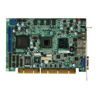
IEI Technology PCISA-945GSE User Manual (190 pages)
PCISA CPU Card with 45 nm Intel Atom CPU, 2x PCIe GbE,512 MB DDR2 Memory, SO-DIMM Slot, CompactFlash, VGA, LVDS, HDTV and SDVO and Dual SATA
Brand:
IEI Technology
| Category:
Computer Hardware
| Size: 3 MB
Table of Contents
Manual Conventions
4
Packing List
6
Table of Contents
7
1 Introduction
19
Introduction
20
Figure 1-1: PCISA-945GSE
20
Overview Photo
21
Figure 1-2: PCISA-945GSE Overview (Front)
21
Peripheral Connectors and Jumpers
22
Figure 1-3: PCISA-945GSE Overview (Rear)
22
Technical Specifications
23
Dimensions
25
Board Dimensions
25
Figure 1-4: PCISA-945GSE Dimensions (MM)
25
Table 1-1: Technical Specifications
25
T Echnical S Pecifications 1.5 D Imensions
25
External Interface Panel Dimensions
26
Figure 1-5: External Interface Panel Dimensions (MM)
26
Data Flow
27
Figure 1-6: Data Flow Block Diagram
27
2 Unpacking
28
Anti-Static Precautions
29
Unpacking
29
Unpacking Precautions
29
Unpacking Checklist
30
Package Contents
30
Optional Items
31
Table 2-1: Packing List
31
Table 2-2: Power Consumption
32
3 Connectors
33
Peripheral Interface Connectors
34
Layout
34
Figure 3-1: Connector and Jumper Locations [Front Side]
34
Internal Peripheral Interface Connectors
35
Figure 3-2: Connector and Jumper Locations [Solder Side]
35
External Interface Panel Connectors
36
Table 3-1: Peripheral Interface Connectors
36
Table 3-2: Rear Panel Connectors
36
Internal Peripheral Connectors
37
ATX Power Control Connector
37
Figure 3-3: ATX Power Supply Enable Connector Location
37
Audio Connector
38
Figure 3-4: Audio Connector Location (9-Pin)
38
Table 3-3: ATX Power Supply Enable Connector Pinouts
38
Backlight Inverter Connector
39
Figure 3-5: LCD Backlight Connector Pinout Locations
39
Table 3-4: Audio Connector Pinouts (9-Pin)
39
Table 3-5: LCD Backlight Connector Pinouts
39
Battery Connector
40
BIOS Programming Connector
40
Figure 3-6: Battery Connector Location
40
Table 3-6: Battery Connector Pinouts
40
Compactflash® Socket
41
Figure 3-7: BIOS Programming Connector Pinouts
41
Table 3-7: BIOS Programming Connector
41
Figure 3-8: CF Card Socket Location
42
Digital I/O Connector
43
Figure 3-9: Digital I/O Connector Locations
43
Table 3-8: CF Card Socket Pinouts
43
Fan Connector
44
Floppy Disk Connector
44
Figure 3-10: CPU Fan Connector Location
44
Table 3-9: DIO Connector Pinouts
44
Table 3-10: CPU Fan Connector Pinouts
44
Figure 3-11: Floppy Disk Connector Location
45
Front Panel Connector
46
Figure 3-12: Front Panel Connector Pinout Locations
46
Table 3-11: Floppy Disk Connector Pinouts
46
IDE Connector
47
Figure 3-13: IDE Device Connector Locations
47
Table 3-12: Front Panel Connector Pinouts
47
Infrared Interface Connector
48
Table 3-13: IDE Connector Pinouts
48
Keyboard/Mouse Connector
49
Figure 3-14: Infrared Connector Pinout Locations
49
Table 3-14: Infrared Connector Pinouts
49
LVDS LCD Connector
50
Figure 3-15: Keyboard/Mouse Connector Location
50
Table 3-15: Keyboard/Mouse Connector Pinouts
50
SATA Drive Connectors
51
Figure 3-16: LVDS LCD Connector Pinout Locations
51
Table 3-16: LVDS LCD Port Connector Pinouts
51
Parallel Port Connector
52
Figure 3-17: SATA Drive Connector Locations
52
Table 3-17: SATA Drive Connector Pinouts
52
Serial Port Connector (RS-232)
53
Figure 3-18: Parallel Port Connector Location
53
Table 3-18: Parallel Port Connector Pinouts
53
Serial Port Connector (RS-232/422/485)
54
Figure 3-19: RS-232 Connector Pinout Locations
54
Table 3-19: RS-232 Connector Pinouts
54
SDVO Connector
55
Figure 3-20: RS-232/422/485 Connector Pinout Locations
55
Table 3-20: RS-232/422/485 Connector Pinouts
55
Figure 3-21: SDVO Connector Pinout Locations
56
TV out Connector
57
Figure 3-22: TV Connector Pinout Locations
57
Table 3-21: SDVO Connector Pinouts
57
Table 3-22: TV Port Connector Pinouts
57
USB Connectors
58
Figure 3-23: USB Connector Pinout Locations
58
Table 3-23: USB Port Connector Pinouts
58
External Peripheral Interface Connector Panel
59
LAN Connectors
59
Figure 3-24: PCISA-945GSE External Peripheral Interface Connector
59
Table 3-24: LAN Connector Pinouts
59
USB Connectors
60
VGA Connector
60
Figure 3-25: LAN Connector
60
Table 3-25: LAN Connector Leds
60
Table 3-26: USB Port Pinouts
60
Figure 3-26: VGA Connector
61
Table 3-27: VGA Connector Pinouts
61
4 Installation
62
Anti-Static Precautions
63
Installation Considerations
64
Installation Notices
64
Installation Checklist
65
Unpacking
65
So-DIMM Installation
66
Cf Card Installation
66
Figure 4-1: SO-DIMM Installation
66
Atx Power Control Connector
67
Figure 4-2: CF Card Installation
67
Figure 4-3: ATX Power Control Connector
68
Jumper Settings
69
Table 4-1: Jumpers
69
AT/ATX Power Selection
70
Figure 4-4: Jumper Location
70
Table 4-2: AT/ATX Power Selection Jumper Settings
70
CF Card Setup
71
Clear CMOS Jumper
71
Table 4-3: Clear CMOS Jumper Settings
71
COM2 RS-232/422/485 Selection Jumper
72
LCD Panel Type Selection
72
Table 4-4: CF Card Setup Jumper Settings
72
Table 4-5: COM2 RS-232/422/485 Selection Jumper Pinouts
72
LVDS Voltage Selection
73
Table 4-6: LCD Panel Type Selection Jumper Settings
73
Table 4-7: LVDS Voltage Selection Jumper Settings
73
Chassis Installation
74
Airflow
74
Motherboard Installation
74
Internal Peripheral Device Connections
74
Channel Audio Kit Installation
75
Table 4-8: IEI Provided Cables
75
Figure 4-5: 5.1 Channel Audio Kit
76
Channel Audio Kit Installation
77
ATA Flat Cable Connection
78
Figure 4-6: 7.1 Channel Audio Kit
78
Dual RS-232 Cable with Slot Bracket
79
Figure 4-7: IDE Cable Connection
79
Floppy Drive Cable Connection
80
Figure 4-8: Dual RS-232 Cable Installation
80
Parallel Port Cable Without Bracket
81
Figure 4-9: FDD Cable Connection
81
SATA Drive Connection
82
Figure 4-10: LPT Cable Connection
82
Figure 4-11: SATA Drive Cable Connection
83
USB Cable (Dual Port) with Slot Bracket
84
Figure 4-12: SATA Power Drive Connection
84
Figure 4-13: Dual USB Cable Connection
85
External Peripheral Interface Connection
86
LAN Connection
86
Figure 4-14: Connect the LPT Device
86
USB Device Connection (Single Connector)
87
Figure 4-15: LAN Connection
87
VGA Monitor Connection
88
Figure 4-16: USB Device Connection
88
Figure 4-17: VGA Connector
89
5 Bios Setup
90
Introduction
91
Starting Setup
91
Using Setup
91
Getting Help
92
Unable to Reboot after Configuration Changes
92
BIOS Menu Bar
92
Table 5-1: BIOS Navigation Keys
92
Main
93
BIOS Menu 1: Main
93
Advanced
94
BIOS Menu 2: Advanced
95
CPU Configuration
96
BIOS Menu 3: CPU Configuration
96
IDE Configuration
97
BIOS Menu 4: IDE Configuration
97
IDE Master, IDE Slave
99
BIOS Menu 5: IDE Master and IDE Slave Configuration
99
Floppy Configuration
104
BIOS Menu 6: IDE Master and IDE Slave Configuration
104
Super IO Configuration
105
BIOS Menu 7: Super IO Configuration
105
Hardware Health Configuration
108
BIOS Menu 8: Hardware Health Configuration
108
Power Configuration
112
ACPI Configuration
112
BIOS Menu 9: Power Configuration
112
BIOS Menu 10: ACPI Configuration
113
APM Configuration
114
BIOS Menu 11:Advanced Power Management Configuration
114
Remote Configuration
117
BIOS Menu 12: Remote Access Configuration
117
USB Configuration
121
BIOS Menu 13: USB Configuration
121
Pci/Pnp
122
BIOS Menu 14: Pci/Pnp Configuration
123
Boot
125
BIOS Menu 15: Boot
125
Boot Settings Configuration
126
BIOS Menu 16: Boot Settings Configuration
126
Boot Device Priority
128
Hard Disk Drives
128
BIOS Menu 17: Boot Device Priority Settings
128
CD/DVD Drives
129
BIOS Menu 18: Hard Disk Drives
129
Removable Drives
130
BIOS Menu 19: CD/DVD Drives
130
BIOS Menu 20: Removable Drives
131
Security
132
BIOS Menu 21: Security
132
Chipset
133
BIOS Menu 22: Chipset
133
Northbridge Chipset Configuration
134
BIOS Menu 23: Northbridge Chipset Configuration
134
Video Function Configuration
136
BIOS Menu 24: Video Function Configuration
136
Southbridge Configuration
138
BIOS Menu 25: Southbridge Chipset Configuration
139
Exit
140
BIOS Menu 26: Exit
140
6 Software Installation
142
Available Software Drivers
143
Starting the Driver Program
143
Figure 6-1: Start up Screen
144
Figure 6-2: Select Operating System
144
Chipset Driver Installation
145
Figure 6-3: Drivers
145
Figure 6-4: Chipset Driver Welcome Screen
146
Figure 6-5: Chipset Driver License Agreement
146
Figure 6-6: Chipset Driver Read Me File
147
Figure 6-7: Chipset Driver Setup Operations
147
Vga Driver Installation
148
Figure 6-8: Chipset Driver Installation Finish Screen
148
Figure 6-9: VGA Driver Read Me File
149
Figure 6-10: VGA Driver Setup Files Extracted
149
Figure 6-11: VGA Driver Welcome Screen
150
Figure 6-12: VGA Driver License Agreement
150
Figure 6-13: VGA Driver Read Me File
151
Figure 6-14: VGA Driver Setup Operations
152
Figure 6-15: VGA Driver Installation Finish Screen
152
Lan Driver Installation
153
Figure 6-16: LAN Driver Welcome Screen
153
Figure 6-17: LAN Driver Welcome Screen
154
Figure 6-18: LAN Driver Installation
154
Audio Driver Installation
155
AC'97 Driver Installation
155
Figure 6-19: LAN Driver Installation Complete
155
Figure 6-20: AC'97 Audio
156
Figure 6-21: AC'97 Audio Driver Options
156
Figure 6-22: AC'97 Driver Installation Welcome Screen
157
Figure 6-23: AC'97 Driver Installation Verification
157
HD Audio Driver Installation
158
Figure 6-24: AC'97 Driver Installation Complete
158
Figure 6-25: HD Audio
159
Figure 6-26: HD Audio Driver Options
159
Figure 6-27: HD Audio Driver Installation Welcome Screen
160
Figure 6-28: HD Audio Driver Installation Complete
160
Ismm Installation
161
Figure 6-29: Ismm Directory
161
Figure 6-30: Ismm Installation File
162
Figure 6-31: Ismm Installshield Welcome Screen
162
Figure 6-32: Ismm License Agreement
163
Figure 6-33: Ismm Customer Information
164
Figure 6-34: Ismm Setup Type
165
Figure 6-35: Ismm Installation Confirmation
166
Figure 6-36: Ismm Installshield Wizard Complete
166
Figure 6-37: Ismm Restart Confirmation
167
ABIOS Options
168
B Terminology
172
C Digital I/O Interface
176
Introduction
177
Dio Connector Pinouts
177
C.1 I Ntroduction
177
Assembly Language Samples
178
Enable the DIO Input Function
178
Enable the DIO Output Function
178
C.3 a Ssembly L Anguage S Amples
178
D Watchdog Timer
179
E Address Mapping
182
Direct Memory Access (Dma)
183
Input/Output (IO)
183
Interrupt Request (Irq)
185
Memory
186
F Hazardous Materials Disclosure
187
Hazardous Materials Disclosure Table for IPB Products Certified as Rohs Compliant under 2002/95/EC Without Mercury
188
Advertisement
IEI Technology PCISA-945GSE Quick Installation Manual (11 pages)
Half-size PCISA SBC with Intel Atom N270 1.6GHz procesor, VGA/LVDS/HDTV-out, dual PCIe GbE, USB2.0 and SATA
Brand:
IEI Technology
| Category:
Motherboard
| Size: 0 MB
Table of Contents
Quick Installation Guide
1
Package Contents
1
Specifications
2
Ordering Information
3
Jumpers Setting and Connectors
4
Board Layout: Jumper and Connector Locations
10
Advertisement
Related Products
IEI Technology PCISA-9652-R10
IEI Technology PCISA-PV-D5251T
IEI Technology PCISA-PV-D4251T
IEI Technology PCISA-PV-D4251
IEI Technology PCISA-PV-N4551T
IEI Technology PCISA-PV-D5251
IEI Technology PCISA-BT
IEI Technology PCISA-BT-E38251
IEI Technology PCISA-PV-N4551-R10
IEI Technology PCISA-PV-D5251-R10
IEI Technology Categories
Motherboard
Touch Panel
Computer Hardware
Single board computers
Desktop
More IEI Technology Manuals
Login
Sign In
OR
Sign in with Facebook
Sign in with Google
Upload manual
Upload from disk
Upload from URL