Sign In
Upload
Manuals
Brands
IEI Technology Manuals
Computer Hardware
PCISA-PV-N4551-R10
IEI Technology PCISA-PV-N4551-R10 Manuals
Manuals and User Guides for IEI Technology PCISA-PV-N4551-R10. We have
1
IEI Technology PCISA-PV-N4551-R10 manual available for free PDF download: User Manual
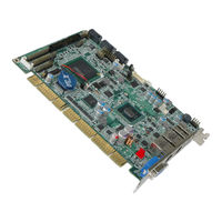
IEI Technology PCISA-PV-N4551-R10 User Manual (145 pages)
Half-Size CPU Card for Intel Atom CPU, DDR3, VGA, LAN, SATA 3Gb/s, USB, HD Audio, RoHS Compliant
Brand:
IEI Technology
| Category:
Computer Hardware
| Size: 7 MB
Table of Contents
Table of Contents
4
Introduction
14
Introduction
15
Model Variations
15
Figure 1-1: PCISA-PV-D4251/N4551/D5251
15
Benefits
16
Features
16
Table 1-1: Model Variations
16
Connectors
17
Figure 1-2: Connectors (Front Side)
17
Figure 1-3: Connectors (Solder Side)
18
Dimensions
19
Figure 1-4: Dimensions (MM)
19
Data Flow
20
Figure 1-5: Data Flow Diagram
20
Technical Specifications
21
Table 1-2: Technical Specifications
22
Packing List
23
Anti-Static Precautions
24
Unpacking Precautions
24
Packing List
25
Optional Items
26
Table 2-1: Packing List
26
Table 2-2: Optional Items
26
Connectors
27
Peripheral Interface Connectors
28
Layout
28
Figure 3-1: Connectors and Jumpers
28
Table 3-1: Internal Peripheral Connectors
29
External Interface Panel Connectors
30
Internal Peripheral Connectors
30
ATX Power Supply Enable Connector
30
Figure 3-2: ATX Power Supply Enable Connector Location
30
Table 3-2: External Peripheral Connectors
30
Audio Connector
31
Figure 3-3: Audio Connector Location
31
Table 3-3: ATX Power Supply Enable Connector Pinouts
31
Table 3-4: AT/ATX Power Mode Setting
31
Battery Connector
32
Figure 3-4: Battery Connector Location
32
Table 3-5: Audio Connector Pinouts
32
Table 3-6: Battery Connector Pinouts
32
Compactflash® Socket
33
Figure 3-5: CF Card Socket Location
33
Digital Input/Output Connector
34
Figure 3-6: DIO Connector Location
34
Table 3-7: CF Card Socket Pinouts
34
Fan Connector
35
Figure 3-7: Fan Connector Locations
35
Table 3-8: DIO Connector Pinouts
35
Floppy Disk Connector (34-Pin)
36
Figure 3-8: 34-Pin FDD Connector Location
36
Table 3-9: Fan Connector Pinouts
36
Flash SPI ROM Connector
37
Figure 3-9: Flash SPI ROM Connector Locations
37
Table 3-10: 34-Pin FDD Connector Pinouts
37
Front Panel Connector
38
Figure 3-10: Front Panel Connector Location
38
Table 3-11: Flash SPI ROM Connector Pinouts
38
IDE Connector
39
Figure 3-11: IDE Device Connector Location
39
Table 3-12: Front Panel Connector Pinouts
39
Infrared Interface Connector
40
Table 3-13: IDE Connector Pinouts
40
Keyboard/Mouse Connector
41
Figure 3-12: Infrared Connector Pinout Locations
41
Figure 3-13: Keyboard/Mouse Connector Location
41
Table 3-14: Infrared Connector Pinouts
41
LCD Backlight Connector
42
Figure 3-14: LCD Backlight Connector Location
42
Table 3-15: Keyboard/Mouse Connector Pinouts
42
LVDS LCD Connector
43
Figure 3-15: LVDS LCD Connector Location
43
Table 3-16: LCD Backlight Connector Pinouts
43
Table 3-17: LVDS LCD Connector Pinouts
43
Parallel Port Connector
44
Figure 3-16: Parallel Port Connector Location
44
Table 3-18: Parallel Port Connector Pinouts
44
Serial Port Connectors (COM1, COM3 and COM4 )
45
Figure 3-17: RS-232 Connector Pinout Locations
45
Table 3-19: RS-232 Connector Pinouts
45
RS-232/422/485 Serial Port Connector (COM2)
46
SATA Drive Connectors
46
Figure 3-18: COM2 Location
46
Table 3-20: COM2 Pinouts
46
Smbus Connector
47
Figure 3-19: SATA Drive Connector Locations
47
Table 3-21: SATA Drive Connector Pinouts
47
USB Connectors (Internal)
48
Figure 3-20: Smbus Connector Location
48
Table 3-22: Smbus Connector Pinouts
48
External Peripheral Interface Connector Panel
49
Figure 3-21: Internal USB Connector Locations
49
Figure 3-22: External Peripheral Interface Connector
49
Table 3-23: USB3 and USB4 Pinouts
49
CRT Connector
50
Ethernet Connectors
50
Figure 3-23: VGA Connector
50
Table 3-24: VGA Connector Pinouts
50
Figure 3-24: RJ-45 Ethernet Connector
51
Table 3-25: LAN1 and LAN2 Pinouts
51
Table 3-26: RJ-45 Ethernet Connector Leds
51
USB Connector
52
Table 3-27: External USB Connector Pinouts
52
Installation
53
Anti-Static Precautions
54
Installation Considerations
54
Basic Installation
56
SO-DIMM Installation
56
Airflow
56
Figure 4-1: SO-DIMM Installation
56
Backplane Installation
57
CPU Card Installation
57
Optional CPU Fan Installation
57
Jumper Settings
58
Figure 4-2: Connect Fan Cable
58
CF Card Setup
59
Table 4-1: Jumpers
59
Table 4-2: CF Card Setup Jumper Settings
59
Clear CMOS Jumper
60
Figure 4-3: CF Card Setup Jumper Location
60
Table 4-3: Clear CMOS Jumper Settings
60
COM 2 Function Select Jumper
61
Figure 4-4: Clear CMOS Jumper
61
Table 4-4: COM 2 Function Select Jumper Settings
61
LVDS Voltage Selection
62
Figure 4-5: COM 2 Function Select Jumper Location
62
LVDS Panel Resolution Selection
63
Figure 4-6: LVDS Voltage Selection Jumper Pinout Locations
63
Table 4-5: LVDS Voltage Selection Jumper Settings
63
Pcie Interface Setup
64
Figure 4-7: LVDS Resolution Selection Jumper Pinout Locations
64
Table 4-6: LVDS Resolution Selection Jumper Settings
64
Table 4-7: Pcie Slot Jumper Setting
64
Internal Peripheral Device Connections
65
SATA Drive Connection
65
Figure 4-8: Pcie Slot Jumper Location
65
Figure 4-9: SATA Drive Cable Connection
66
USB Cable (Dual Port) with Slot Bracket
67
Figure 4-10: SATA Power Drive Connection
67
External Peripheral Interface Connection
68
LAN Connection
68
Figure 4-11: Dual USB Cable Connection
68
USB Device Connection
69
Figure 4-12: LAN Connection
69
VGA Monitor Connection
70
Figure 4-13: USB Device Connection
70
Software Installation
71
Figure 4-14: VGA Connector
71
Bios
72
Introduction
73
Starting Setup
73
Using Setup
73
Getting Help
74
Unable to Reboot after Configuration Changes
74
BIOS Menu Bar
74
Table 5-1: BIOS Navigation Keys
74
Main
75
Advanced
76
Trusted Computing
76
CPU Configuration
77
SATA Configuration
79
USB Configuration
80
Super IO Configuration
81
Floppy Disk Controller Configuration
82
Serial Port N Configuration
83
Irda Configuration
86
Parallel Port Configuration
87
H/W Monitor
88
Serial Port Console Redirection
90
Chipset
91
Host Bridge Configuration
92
Onchip VGA Configuration
93
South Bridge Configuration
94
Intel IGD SWSCI Opregion
95
Boot
97
Security
99
Exit
100
ABIOS Options
102
B Terminology
105
C One Key Recovery
109
One Key Recovery Introduction
110
Figure C-1: IEI One Key Recovery Tool Menu
110
System Requirement
111
Supported Operating System
112
Setup Procedure for Windows
113
Hardware and BIOS Setup
113
Create Partitions
114
Figure C-2: Launching the Recovery Tool
114
Figure C-3: Recovery Tool Setup Menu
115
Figure C-4: Command Mode
115
Figure C-5: Partition Creation Commands
116
Install Operating System, Drivers and Applications
117
Build-Up Recovery Partition
118
Figure C-6: Launching the Recovery Tool
118
Figure C-7: System Configuration for Windows
118
Figure C-8: Build-Up Recovery Partition
119
Figure C-9: Press any Key to Continue
119
Create Factory Default Image
120
Figure C-10: Press F3 to Boot into Recovery Mode
120
Figure C-11: Recovery Tool Menu
120
Figure C-12: about Symantec Ghost Window
121
Figure C-13: Symantec Ghost Path
121
Figure C-14: Select a Local Source Drive
122
Figure C-15: Select a Source Partition from Basic Drive
122
Figure C-16: File Name to Copy Image to
123
Figure C-17: Compress Image
123
Figure C-18: Image Creation Confirmation
124
Figure C-19: Image Creation Complete
124
Figure C-20: Image Creation Complete
124
Setup Procedure for Linux
125
Figure C-21: Press any Key to Continue
125
Figure C-22: Partitions for Linux
126
Figure C-23: System Configuration for Linux
127
Figure C-24: Access Menu.lst in Linux (Text Mode)
127
Recovery Tool Functions
128
Figure C-25: Recovery Tool Menu
128
Figure C-26: Recovery Tool Main Menu
129
Factory Restore
130
Figure C-27: Restore Factory Default
130
Figure C-28: Recovery Complete Window
130
Backup System
131
Figure C-29: Backup System
131
Figure C-30: System Backup Complete Window
131
Restore Your Last Backup
132
Figure C-31: Restore Backup
132
Figure C-32: Restore System Backup Complete Window
132
Manual
133
Figure C-33: Symantec Ghost Window
133
Other Information
134
Using AHCI Mode or Ali M5283 / VIA VT6421A Controller
134
System Memory Requirement
136
D Watchdog Timer
137
E Digital I/O Interface
140
Introduction
141
Dio Connector Pinouts
141
Assembly Language Example
141
F Hazardous Materials Disclosure
142
Hazardous Materials Disclosure Table for IPB Products Certified as Rohs Compliant under 2002/95/EC Without Mercury
143
Advertisement
Advertisement
Related Products
IEI Technology PCISA-PV-D5251T
IEI Technology PCISA-PV-D4251T
IEI Technology PCISA-PV-N4551
IEI Technology PCISA-PV-D4251
IEI Technology PCISA-PV-N4551T
IEI Technology PCISA-PV-D5251
IEI Technology PCISA-PV-D5251-R10
IEI Technology PCISA-MARK
IEI Technology PCISA-6612
IEI Technology PCISA-BT
IEI Technology Categories
Motherboard
Touch Panel
Computer Hardware
Single board computers
Desktop
More IEI Technology Manuals
Login
Sign In
OR
Sign in with Facebook
Sign in with Google
Upload manual
Upload from disk
Upload from URL