Sign In
Upload
Manuals
Brands
IEI Technology Manuals
Desktop
PPC-5150GS
IEI Technology PPC-5150GS Panel PC Manuals
Manuals and User Guides for IEI Technology PPC-5150GS Panel PC. We have
1
IEI Technology PPC-5150GS Panel PC manual available for free PDF download: User Manual
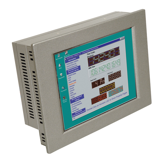
IEI Technology PPC-5150GS User Manual (170 pages)
Flat Panel PC
Brand:
IEI Technology
| Category:
Desktop
| Size: 3 MB
Table of Contents
Table of Contents
8
1 Introduction
17
Ppc-5150Gs Flat Panel Pc Overview
18
PPC-5150GS Flat Panel PC Applications
18
PPC-5150GS Flat Panel PC Features
18
PPC-5150GS Model Variation
18
Table 1-1: PPC-5150GS Model Variation
18
Ppc-5150Gs External Overview
19
Front Panel
19
General Description
19
Rear Panel
20
Top Panel
20
Figure 1-1: PPC-5150GS Front View
20
Figure 1-2: PPC-5150GS Rear View
20
Figure 1-3: PPC-5150GS Top View
21
Figure 1-4: Bottom View
21
PPC-5150GS Bottom Panel
21
Figure 1-5: Right View
22
Figure 1-6: Left View
22
Frame
22
Left Panel
22
Right Panel
22
Ppc-5150Gs Internal Overview
23
Ppc-5150Gs Specifications
23
Preinstalled Hardware Components
23
System Specifications
23
Figure 1-7: Frame Rear View (12 Panel Mount Retention Screw Holes)
23
PPC-5150GS Motherboard Specifications
25
Table 1-2: PPC-5150GS Specifications
25
Flat Panel Screen
26
Table 1-3: Motherboard Specifications
26
Power Supply
27
Table 1-4: 15" TFT LCD Monitor Specifications
27
Dimensions
28
Table 1-5: Power Supply Specifications
28
Figure 1-8: Dimensions (Units in MM)
29
2 Pos-8520 Motherboard
31
Introduction
32
Cpu Support
32
On-Board Chipsets
32
852GME Northbridge Chipset
32
Northbridge and Southbridge Chipsets
32
ICH5 Southbridge Chipset
33
Graphics Support
34
Peripheral Device Interfaces, Connectors, and Slots
36
Internal Peripheral Device Connectors
36
Internal Slots
36
OEM Options
36
External Peripheral Device Connectors
37
3 Installation and Configuration
39
Installation Precautions
40
Preinstalled Components
40
Installation and Configuration Steps
41
Unpacking
41
Packing List
42
Jumper Settings
42
Remove the
43
Table 3-1: Onboard Jumpers
43
CF Card Setup (JP12)
44
Clear CMOS Setup (JP1)
44
Table 3-2: CF Card Setup Jumper Settings
44
COM Port RI and Voltage Selection
45
COM2 Port RS232/422/485 Selection (JP10, JP20)
45
Figure 3-1: Back Cover Retention Screws
44
Table 3-3: Clear CMOS Jumper Settings
45
Table 3-4: COM2 Port Jumper Settings
45
Table 3-5: COM1 RI and Voltage Selection Jumper
45
Table 3-6: COM1 RI Voltage Selection Jumper
45
Table 3-7: COM2 RI and Voltage Selection Jumper
46
Table 3-8: COM2 RI Voltage Selection Jumper
46
Table 3-9: COM3 RI and Voltage Selection Jumper
46
CPU Voltage Setting (S3)
47
Keyboard and Mouse Power Source Setting (JP18)
47
LCD Voltage Setup (JP2)
47
Table 3-10: COM3 RI Voltage Selection Jumper
46
Table 3-11: COM4 RI and Voltage Selection Jumper
47
Table 3-12: COM4 RI Voltage Selection Jumper
47
Table 3-13: CPU Voltage Setting
47
Table 3-14: Keyboard and Mouse Power Source Setting
47
Hdd, Fdd and CD Drive Installation
48
HDD Installation
48
Figure 3-2: HDD Retention Screws
48
Table 3-15: LCD Voltage Setup Jumper Settings
48
FDD Installation
49
Figure 3-3: FDD Retention Screws
49
CD Drive Installation
50
Figure 3-4: FDD Adapter and FDD Bracket Installation
50
Figure 3-5: CD Drive Adapter Installation
51
Figure 3-6: CD Drive Retention Screws
51
Figure 3-7: Remove CD Drive
51
Figure 3-8: CD Drive Blank Plate Assembly
52
Figure 3-9: CD Drive Blank Plate Assembly
52
Figure 3-10: CD Drive Installed
53
Wall Mounting
54
Figure 3-11: Wall-Mounting Bracket
54
Figure 3-12: Mount the Chassis
55
Panel Mounting
56
Figure 3-13: Secure the Chassis
56
Figure 3-14: Cut the Panel
57
Arm Mounting
58
Figure 3-15: Panel Mounting Clamp Positions
58
Figure 3-16: Tighten the Panel Mounting Clamp Screws
58
Cabinet and Rack Installation
59
Figure 3-17: Arm Mount Retention Screw Holes
59
Figure 3-18: Secure the Rack/Cabinet Bracket
60
Mounting the System
53
Rear Panel Connectors
61
LCD Panel Connection
61
Figure 3-19: Install into a Rack/Cabinet
61
Ethernet Connection
62
USB Connection
62
Keyboard and Mouse Connection
62
Parallel Port Connection
62
4 System Maintenance
63
System Maintenance Introduction
64
Motherboard Replacement
64
Back Cover Removal and Elevated Platform Detachment
64
Back Cover Removal
64
Detaching the Elevated Platform
65
Figure 4-1: Rear Cover Retention Screws (Real Panel)
65
Figure 4-3: Elevated Platform Retention Screws (Top Panel)
66
Figure 4-4: Elevated Platform Retention Screws (Right Panel)
66
DIMM Replacement
67
Figure 4-2: Internal Elevated Platform Retention Screws
66
Figure 4-5: Elevated Platform Retention Screws (Bottom Panel)
67
Figure 4-6: PCI Riser Card Retention Screws
67
Figure 4-7: DIMM Socket Clip Locations
68
Psu Module Replacement
68
Figure 4-8: PSU Motherboard Connector
69
Figure 4-9: PSU Internal Retention Screws
69
Figure 4-10: PSU External Retention Screws
69
5 Ami Bios
71
Introduction
72
Starting Setup
72
Using Setup
72
BIOS Menu Bar
73
Getting Help
73
Unable to Reboot after Configuration Changes
73
Table 5-1: BIOS Navigation Keys
73
Main
74
System Overview
74
Advanced
75
System Date [XX/XX/XX]
75
CPU Configuration
76
IDE Configuration
78
System Time [XX:XX:XX]
75
Hyper Threading Technology [Disabled]
78
Max CUPID Value Limit [Disabled]
78
IDE Configuration [P-ATA Only]
79
S-ATA Running Enhanced Mode [Yes]
79
Configure S-ATA as RAID [No]
80
P-ATA Channel Selection [Both]
80
Rd ./P1-4 Th .]
80
S-ATA Ports Definition
80
ATA (PI) 80Pin Cable Detection [Host & Device]
81
IDE Master, IDE Slave
82
Hard Disk Write Protect [Disabled]
81
IDE Detect Time out (Sec) [35]
81
IDE Master and IDE Slave
82
Auto-Detected Drive Parameters
83
Lba/Large Mode [Auto]
84
Type [Auto]
84
Zip
84
Block (Multi Sector Transfer) [Auto]
85
PIO Mode [Auto]
85
Floppy Configuration
86
32Bit Data Transfer [Disabled]
86
Floppy a [1.44 MB 3½"]
87
Super IO Configuration
87
Auto]
86
On Board Floppy Controller [Enabled]
88
Serial Port1 Address [3F8/IRQ4]
88
Parallel Port Address [378]
89
Serial Port2 Address [2F8/IRQ3]
89
Serial Port2 Mode [Normal]
89
Digital I/O Address [280H]
90
Parallel Port IRQ [IRQ7]
90
Parallel Port Mode [Normal]
90
Serial Port3 Address [3E8]
91
Serial Port3 IRQ [11]
91
Serial Port4 Address [2E8]
91
Serial Port4 IRQ [10]
92
Serial Port5 Address [2F0]
92
Serial Port5 IRQ [11]
92
Hardware Health Configuration
93
Serial Port6 Address [2E0]
93
Serial Port6 IRQ [10]
93
H/W Health Function [Enabled]
94
ACPI Configuration
95
General ACPI Configuration
95
Advanced ACPI Configuration
96
Suspend Mode [S1 (POS)]
96
ACPI 2.0 Features [No]
97
ACPI APIC Support [Enabled]
97
AMI OEMB Table [Enabled]
98
APIC ACPI SCI IRQ [Disabled]
98
Headless Mode [Disabled]
98
MPS Configuration
99
MPS Revision [1.4]
99
Remote Access Configuration
100
USB Configuration
100
Flow Control
100
Redirection after BIOS POST
100
Remote Access [Disabled]
100
Serial Port Mode
100
Serial Port Number
100
Terminal Type
100
VT-UTF8 Combo Key Support
100
USB Configuration
101
USB Devices Enabled
101
USB Function [8 USB Ports]
101
Legacy USB Support [Disabled]
102
Pci/Pnp
102
USB 2.0 Controller [Enabled]
102
Plug & Play O/S [No]
103
Allocate IRQ to PCI VGA [Yes]
104
Palette Snooping [Disabled]
104
PCI Latency Timer [64]
104
Offboard PCI/ISA IDE Card [Auto]
105
PCI IDE Busmaster [Disabled]
105
DMA Channel# [Available]
106
IRQ# [Available]
106
Boot
107
Reserved Memory Size [Disabled]
107
Boot Settings Configuration
108
Quick Boot [Enabled]
109
Quiet Boot [Disabled]
109
Addon ROM Display Mode [Force BIOS]
110
Bootup Num-Lock [On]
110
PS/2 Mouse Support [Auto]
110
Boot Device Priority
111
Removable Drives
112
Change Supervisor Password
113
Change User Password
113
Security
113
Chipset
114
Northbridge Configuration
114
Configure DRAM Timing by SPD [Enabled]
115
DRAM Frequency [Auto]
115
Init. Graphic Adapter Priority [Pci/Int-VGA]
116
Memory Hole [Disabled]
116
Boot Display Device [CRT+LFP]
117
Flat Panel Type [640X480]
117
Southbridge Configuration
118
Graphics Aperture Size [64MB]
117
Internal Graphics Mode Select [Enable, 8MB]
117
Onboard AC97 Audio [Auto]
119
Power
119
Power Management/Apm [Enabled]
119
Hard Disk Power down Mode [Suspend]
120
Standby Time out [Disabled]
120
Video Power down Mode [Suspend]
120
Power Button Mode [On/Off]
121
Suspend Time out [Disabled]
121
Restore on AC Power Loss [Last State]
122
Resume on PME# [Disabled]
122
Resume on Ring/Lan [Disabled]
122
Resume on RTC Alarm [Disabled]
122
Exit
123
RTC Alarm Date (Days)
123
System Time
123
Discard Changes
124
Discard Changes and Exit
124
Load Optimal Defaults
124
Save Changes and Exit
124
Ainterface Connectors
125
Floppy Disk Drive Connector
126
Pci E-Ide Disk Drive Connector
127
Parallel Port
128
Serial Ports
128
Keyboard / Mouse Connector
132
External Switches and Indicators
133
Usb Port Connector
134
Irda Infrared Interface Port
134
Vga Connector
135
Lan Rj45 Connector
136
Fan Connector
136
Inverter (LCD Backlight) Connector
137
Lcd Panel Lvds Interface Connector
137
Audio Connectors
138
Digital Input / Output
138
Compact Flash Type II Storage Card Socket
139
Atx Power Connector
140
Atx 12V Power Connector
140
Internal Switches and Indicators
141
Serial Ata Connector
141
Bbios Configuration Options
143
Bios Configuration Options
143
B.1 BIOS Configuration Options
144
Csoftware Drivers
149
Introduction
150
Driver Installation
150
Touch Panel Driver Configuration
157
Diei Panel Pc Product Line
159
Iei Panel Pc Products
160
IEI Panel PC Product Series
160
Overview
160
Panel Pc Product Solutions
160
Series Panel PC Solutions
160
Series Panel PC Solutions
161
Series Panel PC Solutions
163
Series Panel PC Solutions
165
Series Panel PC Solutions
167
Eindex
169
Advertisement
Advertisement
Related Products
IEI Technology PPC-5150A-H61-P/R-R10
IEI Technology PPC-5150AD-H61-P/R-R10
IEI Technology PPC-5150A-H61-i3/R-R10
IEI Technology PPC-5150AD-H61-i3/R-R10
IEI Technology PPC-5150A-H61-i5/R-R10
IEI Technology PPC-5150AD-H61-i5/R-R10
IEI Technology PPC-51 A-H61 Series
IEI Technology PPC-5170A-H61-P/R-R10
IEI Technology PPC-5170AD-H61-i5/R-R10
IEI Technology PPC-5190A-H61-P/R-R10
IEI Technology Categories
Motherboard
Touch Panel
Computer Hardware
Single board computers
Desktop
More IEI Technology Manuals
Login
Sign In
OR
Sign in with Facebook
Sign in with Google
Upload manual
Upload from disk
Upload from URL