Sign In
Upload
Manuals
Brands
IEI Technology Manuals
Motherboard
PCIE-H810
User Manuals: IEI Technology PCIE-H810 Motherboard
Manuals and User Guides for IEI Technology PCIE-H810 Motherboard. We have
1
IEI Technology PCIE-H810 Motherboard manual available for free PDF download: User Manual
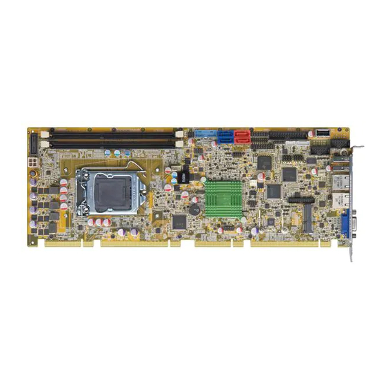
IEI Technology PCIE-H810 User Manual (142 pages)
Full-Size PICMG 1.3 CPU CArd Supports 4th Generation LGA1150 Intel Core i7/i5/i3, Pentium or Celeron CPU, Intel H81 Chipset, DDR3, VGA, iDP, Dual PCIe GbE, SATA 6Gb/s; mSATA, RS-232, HD Audio and RoHS
Brand:
IEI Technology
| Category:
Motherboard
| Size: 3 MB
Table of Contents
Table of Contents
5
1 Introduction
15
Introduction
16
Features
16
Figure 1-1: PCIE-H810
16
Connectors
17
Figure 1-2: Connectors
17
Dimensions
18
Figure 1-3: PCIE-H810 Dimensions (MM)
18
Figure 1-4: External Interface Panel Dimensions (MM)
19
Data Flow
20
Figure 1-5: Data Flow Diagram
20
Technical Specifications
21
Table 1-1: PCIE-H810 Specifications
23
2 Packing List
24
Anti-Static Precautions
25
Unpacking Precautions
25
Packing List
26
Optional Items
26
Table 2-1: Packing List
26
Table 2-2: Optional Items
28
3 Connectors
29
Peripheral Interface Connectors
30
PCIE-H810 Layout
30
Figure 3-1: Connectors and Jumpers
30
Peripheral Interface Connectors
31
External Interface Panel Connectors
32
Table 3-1: Peripheral Interface Connectors
32
Table 3-2: Rear Panel Connectors
32
Internal Peripheral Connectors
33
Power Connector
33
Audio Kit Connector
33
Figure 3-2: +12V Power Connector Pinout Location
33
Table 3-3: +12V Power Connector Pinouts
33
Battery Connector
34
Figure 3-3: Audio Kit Connector Location
34
Table 3-4: Audio Kit Connector Pinouts
34
Chassis Intrusion Connector
35
Figure 3-4: Battery Connector Location
35
Figure 3-5: Chassis Intrusion Connector Location
35
Table 3-5: Battery Connector Pinouts
35
DDR3 DIMM Slots
36
Digital I/O Connector
36
Figure 3-6: DDR3 DIMM Slot Locations
36
Table 3-6: Chassis Intrusion Connector Pinouts
36
EC Debug Connector
37
Figure 3-7: Digital I/O Connector Location
37
Table 3-7: Digital I/O Connector Pinouts
37
Fan Connector (CPU)
38
Figure 3-8: EC Debug Connector Location
38
Table 3-8: EC Debug Connector Pinouts
38
Fan Connector (System)
39
Figure 3-9: CPU Fan Connector Location
39
Table 3-9: CPU Fan Connector Pinouts
39
Front Panel Connector
40
Figure 3-10: System Fan Connector Location
40
Figure 3-11: Front Panel Connector Location
40
Table 3-10: System Fan Connector Pinouts
40
I 2 C Connector
41
Figure 3-12: I 2 C Connector Location
41
Table 3-11: Front Panel Connector Pinouts
41
Table 3-12: I2C Connector Pinouts
41
Infrared Connector
42
Internal Displayport Connector
42
Figure 3-13: Infrared Connector Location
42
Table 3-13: Infrared Connector Pinouts
42
Keyboard and Mouse Connector
43
Figure 3-14: Internal Displayport Connector Location
43
Table 3-14: Internal Displayport Connector Pinouts
43
LAN LED Connectors
44
Figure 3-15: Keyboard and Mouse Connector Location
44
Table 3-15: Keyboard and Mouse Connector Pinouts
44
Parallel Port Connector
45
Figure 3-16: LAN LED Connector Locations
45
Table 3-16: LAN1 LED Connector (LED_LAN1) Pinouts
45
Table 3-17: LAN2 LED Connector (LED_LAN2) Pinouts
45
Figure 3-17: Parallel Port Connector Location
46
Table 3-18: Parallel Port Connector Pinouts
46
Pcie Mini Slot
47
Figure 3-18: Pcie Mini Slot Location
47
SATA 3Gb/S Drive Connectors
48
Table 3-19: Pcie Mini Slot Pinouts
48
SATA 6Gb/S Drive Connectors
49
Figure 3-19: SATA 3Gb/S Drive Connector Location
49
Table 3-20: SATA 3Gb/S Drive Connector Pinouts
49
Serial Port Connectors, RS-232
50
Figure 3-20: SATA 6Gb/S Drive Connector Location
50
Table 3-21: SATA 6Gb/S Drive Connector Pinouts
50
Serial Port Connector, RS-422/485
51
Figure 3-21: Serial Port Connector Location
51
Table 3-22: Serial Port Connector Pinouts
51
Smbus Connector
52
Figure 3-22: RS-422/485 Connector Location
52
Table 3-23: RS-422/485 Connector Pinouts
52
Table 3-24: DB-9 RS-422/485 Pinouts
52
SPI Flash Connector
53
Figure 3-23: Smbus Connector Location
53
Figure 3-24: SPI Flash Connector Location
53
Table 3-25: Smbus Connector Pinouts
53
SPI Flash Connector (EC)
54
Figure 3-25: SPI EC Flash Connector Location
54
Table 3-26: SPI Flash Connector Pinouts
54
Table 3-27: SPI EC Flash Connector Pinouts
54
TPM Connector
55
Figure 3-26: TPM Connector Location
55
Table 3-28: TPM Connector Pinouts
55
USB 2.0 Connectors
56
Figure 3-27: USB 2.0 Connector Pinout Locations
56
Table 3-29: USB 2.0 Connector Pinouts
56
USB 2.0 Connector (Type A)
57
USB 3.1 Gen 1 Connector
57
Figure 3-28: USB 2.0 Connector (Type A) Pinout Location
57
Table 3-30: USB 2.0 Connector (Type A) Pinouts
57
External Peripheral Interface Connector Panel
58
Figure 3-29: USB 3.1 Gen 1 Connector Location
58
Figure 3-30: External Peripheral Interface Connector
58
Table 3-31: USB 3.1 Gen 1 Connector Pinouts
58
Ethernet Connectors
59
Figure 3-31: Ethernet Connector
59
Table 3-32: LAN Pinouts
59
Table 3-33: Connector Leds
59
USB 2.0 Connectors
59
Figure 3-32: VGA Connector
60
Table 3-34: USB 2.0 Port Pinouts
60
Table 3-35: VGA Connector Pinouts
60
VGA Connector
60
4 Installation
61
Anti-Static Precautions
62
Installation Considerations
62
Socket Lga1150 Cpu Installation
64
Figure 4-1: Disengage the CPU Socket Load Lever
64
Figure 4-2: Remove Protective Cover
65
Figure 4-3: Insert the Socket LGA1150 CPU
66
Figure 4-4: Close the Socket LGA1150
66
Socket Lga1150 Cooling Kit Installation
67
Figure 4-5: Cooling Kit Support Bracket
67
DIMM Installation
68
Figure 4-6: DIMM Installation
68
Full-Size Pcie Mini Card Installation
69
Figure 4-7: Removing the Retention Screw and Standoff for a Half-Size Pcie Mini Card
69
Figure 4-8: Removing the Retention Screw
70
Figure 4-9: Inserting the Full-Size Pcie Mini Card into the Slot at an Angle
70
Half-Size Pcie Mini Card Installation
71
Figure 4-10: Securing the Full-Size Pcie Mini Card
71
Figure 4-11: Removing the Retention Screw
72
Figure 4-12: Inserting the Half-Size Pcie Mini Card into the Slot at an Angle
72
System Configuration
73
AT/ATX Power Mode Setting
73
Figure 4-13: Securing the Half-Size Pcie Mini Card
73
Figure 4-14: AT/ATX Power Mode Switch Location
73
Clear CMOS Button
74
Flash Descriptor Security Override
74
Figure 4-15: Clear CMOS Button Location
74
Figure 4-16: Flash Descriptor Security Override Jumper Location
74
Table 4-1: AT/ATX Power Mode Switch Settings
74
Table 4-2: Flash Descriptor Security Override Jumper Settings
74
Msata Mode Selection
75
USB Power Selection
75
Figure 4-17: Msata Mode Selection Jumper Location
75
Table 4-3: Msata Mode Selection Jumper Settings
75
Table 4-4: BIOS Options and Configured USB Ports
75
Table 4-5: USB Power Source Setup
75
Chassis Installation
76
Airflow
76
CPU Card Installation
76
Internal Peripheral Device Connections
77
SATA Drive Connection
77
Figure 4-18: SATA Drive Cable Connection
77
Figure 4-19: SATA Power Drive Connection
78
5 Bios
79
Introduction
80
Starting Setup
80
Using Setup
80
Getting Help
81
Unable to Reboot after Configuration Changes
81
BIOS Menu Bar
81
Table 5-1: BIOS Navigation Keys
81
Main
82
BIOS Menu 1: Main
82
Advanced
83
ACPI Settings
84
BIOS Menu 2: Advanced
84
BIOS Menu 3: ACPI Configuration
84
RTC Wake Settings
85
BIOS Menu 4: RTC Wake Settings
85
Trusted Computing
87
BIOS Menu 5: TPM Configuration
87
CPU Configuration
88
BIOS Menu 6: CPU Configuration
88
SATA Configuration
90
BIOS Menu 7: SATA Configuration
90
USB Configuration
91
BIOS Menu 8: USB Configuration
91
F81866 Super IO Configuration
92
Serial Port N Configuration
92
BIOS Menu 9: F81866 Super IO Configuration
92
BIOS Menu 10: Serial Port N Configuration Menu
92
Irda Configuration
97
BIOS Menu 11: Irda Configuration Menu
97
Parallel Port Configuration
99
BIOS Menu 12: Parallel Port Configuration Menu
99
Iwdd H/W Monitor
100
BIOS Menu 13: Iwdd H/W Monitor
100
Smart Fan Mode Configuration
101
BIOS Menu 14: Smart Fan Mode Configuration
101
Serial Port Console Redirection
102
BIOS Menu 15: Serial Port Console Redirection
103
Iei Feature
105
BIOS Menu 16: IEI Feature
105
Chipset
106
BIOS Menu 17: Chipset
106
PCH-IO Configuration
107
BIOS Menu 18: PCH-IO Configuration
107
Table 5-2: BIOS Options and Configured USB Ports
108
PCI Express Configuration
109
BIOS Menu 19: PCI Express Configuration
109
BIOS Menu 20: PCIEX4_1 Slot Configuration Menu
109
PCH Azalia Configuration
111
BIOS Menu 21: PCH Azalia Configuration
111
System Agent (SA) Configuration
112
Graphics Configuration
112
BIOS Menu 22: System Agent (SA) Configuration
112
BIOS Menu 23: Graphics Configuration
113
BIOS Menu 24: LCD Control
114
NB Pcie Configuration
115
BIOS Menu 25: NB Pcie Configuration
115
Memory Configuration
116
BIOS Menu 26: Memory Configuration
116
Boot
117
BIOS Menu 27: Boot
117
Security
119
Save & Exit
119
BIOS Menu 28: Security
119
BIOS Menu 29: Save & Exit
120
6 Software Drivers
121
Available Drivers
122
Driver Download
122
Figure 6-1: IEI Resource Download Center
122
A Regulatory Compliance
124
BBIOS Options
126
C Terminology
130
D Digital I/O Interface
134
E Watchdog Timer
137
F Hazardous Materials Disclosure
140
Advertisement
Advertisement
Related Products
IEI Technology PCIE-G41A2
IEI Technology PCIE-G41A
IEI Technology PCIE-Q57A
IEI Technology PCIE-Q670-R10
IEI Technology PCIE-Q670-DVI-R10
IEI Technology PCIE-Q670-R20
IEI Technology PCIE-Q170
IEI Technology PCIE-Q870-i2
IEI Technology PCISA-9652
IEI Technology PM-PV-D4251
IEI Technology Categories
Motherboard
Touch Panel
Computer Hardware
Single board computers
Desktop
More IEI Technology Manuals
Login
Sign In
OR
Sign in with Facebook
Sign in with Google
Upload manual
Upload from disk
Upload from URL