Sign In
Upload
Manuals
Brands
IEI Technology Manuals
Motherboard
PCIE-Q670-DVI-R10
IEI Technology PCIE-Q670-DVI-R10 Manuals
Manuals and User Guides for IEI Technology PCIE-Q670-DVI-R10. We have
1
IEI Technology PCIE-Q670-DVI-R10 manual available for free PDF download: User Manual
IEI Technology PCIE-Q670-DVI-R10 User Manual (164 pages)
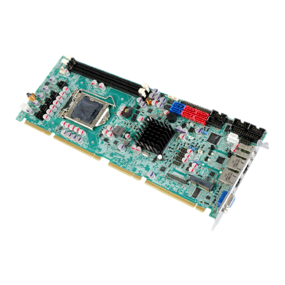
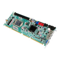
PCIE-Q670 Series
Brand:
IEI Technology
| Category:
Motherboard
| Size: 8 MB
Table of Contents
User Manual
1
Table of Contents
5
1 Introduction
15
Introduction
16
Figure 1-1: PCIE-Q670 Series
16
Model Variations
17
Features
17
Table 1-1: PCIE-Q670 Series Model Variations
17
Connectors
18
Figure 1-2: Connectors
18
Dimensions
19
Figure 1-3: PCIE-Q670 Series Dimensions (MM)
19
Figure 1-4: External Interface Panel Dimensions (MM)
20
Data Flow
21
Figure 1-5: Data Flow Diagram
21
Technical Specifications
22
Table 1-2: PCIE-Q670 Series Specifications
24
2 Packing List
25
Anti-Static Precautions
26
Unpacking Precautions
26
Packing List
27
Optional Items
28
Table 2-1: Packing List
28
Table 2-2: Optional Items
30
3 Connectors
31
Peripheral Interface Connectors
32
PCIE-Q670 Series Layout
32
Figure 3-1: Connectors and Jumpers
32
External Interface Panel Connectors
33
Table 3-1: Peripheral Interface Connectors
33
Internal Peripheral Connectors
34
Power Connector
34
Audio Kit Connector
34
Figure 3-2: ATX Power Connector Pinout Location
34
Table 3-2: Rear Panel Connectors
34
Table 3-3: ATX Power Connector Pinouts
34
Battery Connector
35
Figure 3-3: Audio Connector Location
35
Table 3-4: Audio Connector Pinouts
35
DDR3 DIMM Slots
36
Figure 3-4: Battery Connector Location
36
Table 3-5: Battery Connector Pinouts
36
Digital I/O Connector
37
Figure 3-5: DDR3 DIMM Slot Locations
37
Figure 3-6: Digital I/O Connector Location
37
DVI-D Connector (DVI Model Only)
38
Figure 3-7: DVI-D Connector Location
38
Table 3-6: Digital I/O Connector Pinouts
38
Fan Connector (CPU)
39
Figure 3-8: CPU Fan Connector Location
39
Table 3-7: DVI-D Connector Pinouts
39
Table 3-8: CPU Fan Connector Pinouts
39
Front Panel Connector
40
Figure 3-9: Front Panel Connector Location
40
Table 3-9: Front Panel Connector Pinouts
40
I 2 C Connector
41
Infrared Interface Connector
41
Figure 3-10: I 2 C Connector Location
41
Table 3-10: I 2 C Connector Pinouts
41
Keyboard/Mouse Connector
42
Figure 3-11: Infrared Connector Location
42
Table 3-11: Infrared Connector Pinouts
42
Parallel Port Connector
43
Figure 3-12: Keyboard/Mouse Connector Location
43
Table 3-12: Keyboard/Mouse Connector Pinouts
43
Pcie Mini Card Slot
44
Figure 3-13: Parallel Port Connector Location
44
Table 3-13: Parallel Port Connector Pinouts
44
Figure 3-14: Pcie Mini Card Slot Location
45
SATA 3Gb/S Drive Connector
46
Figure 3-15: SATA 3Gb/S Drive Connector Location
46
Table 3-14: Pcie Mini Card Slot Pinouts
46
Table 3-15: SATA 3Gb/S Drive Connector Pinouts
46
SATA 6Gb/S Drive Connector
47
Serial Port Connectors, RS-232
47
Figure 3-16: SATA 6Gb/S Drive Connector Location
47
Table 3-16: SATA 6Gb/S Drive Connector Pinouts
47
Serial Port Connector, RS-422/485
48
Figure 3-17: Serial Port Connector Location
48
Table 3-17: Serial Port Connector Pinouts
48
Smbus Connector
49
Figure 3-18: RS-422/485 Connector Location
49
Table 3-18: RS-422/485Connector Pinouts
49
Table 3-19: DB-9 RS-422/485 Pinouts
49
SPI ROM Connector
50
Figure 3-19: Smbus Connector Location
50
Table 3-20: Smbus Connector Pinouts
50
TPM Connector
51
Figure 3-20: SPI Connector Location
51
Table 3-21: SPI Connector Pinouts
51
USB Connectors
52
Figure 3-21: TPM Connector Location
52
Table 3-22: TPM Connector Pinouts
52
External Peripheral Interface Connector Panel
53
Ethernet Connectors
53
Figure 3-22: USB Connector Pinout Locations
53
Figure 3-23: External Peripheral Interface Connector
53
Table 3-23: USB Port Connector Pinouts
53
USB Connectors
54
Figure 3-24: Ethernet Connector
54
Table 3-24: LAN Pinouts
54
Table 3-25: Connector Leds
54
VGA Connector
55
Figure 3-25: VGA Connector
55
Table 3-26: USB Port Pinouts
55
Table 3-27: VGA Connector Pinouts
55
4 Installation
56
Anti-Static Precautions
57
Installation Considerations
57
Socket LGA1155 CPU Installation
59
Figure 4-1: Disengage the CPU Socket Load Lever
59
Figure 4-2: Remove Protective Cover
60
Figure 4-3: Insert the Socket LGA1155 CPU
61
Figure 4-4: Close the Socket LGA1155
61
Socket LGA1155 Cooling Kit Installation
62
Figure 4-5: Cooling Kit Support Bracket
62
DIMM Installation
63
Figure 4-6: DIMM Installation
63
Jumper Settings
64
AT/ATX Power Select Jumper
64
Table 4-1: Jumpers
64
Clear CMOS Jumper
65
Figure 4-7: AT/ATX Power Mode Jumper Location
65
Table 4-2: AT/ATX Power Mode Jumper Settings
65
Table 4-3: Clear BIOS Jumper Settings
65
Wake-On LAN Jumper
66
Figure 4-8: Clear BIOS Jumper Location
66
Figure 4-9: Wake-On LAN Connector Pinout Locations
66
Table 4-4: Wake-On LAN Connector Pinouts
66
Chassis Installation
67
Airflow
67
CPU Card Installation
67
Internal Peripheral Device Connections
67
Dual RS-232 Cable with Slot Bracket
67
DVI-D/USB Kit Installation (DVI Model Only)
68
Figure 4-10: Dual RS-232 Cable Installation
68
SATA Drive Connection
69
Figure 4-11: DVI-D/USB Kit Installation
69
Figure 4-12: SATA Drive Cable Connection
70
USB Cable (Dual Port) with Slot Bracket
71
Figure 4-13: SATA Power Drive Connection
71
Pcie Mini Card Installation
72
Figure 4-14: Dual USB Cable Connection
72
External Peripheral Interface Connection
73
LAN Connection
73
Figure 4-15: Pcie Mini Card Installation
73
USB Device Connection (Single Connector)
74
Figure 4-16: LAN Connection
74
VGA Monitor Connection
75
Figure 4-17: USB Device Connection
75
Intel ® Amt Setup Procedure
76
Figure 4-18: VGA Connector
76
5 Bios
78
Introduction
79
Starting Setup
79
Using Setup
79
Getting Help
80
Unable to Reboot after Configuration Changes
80
BIOS Menu Bar
80
Table 5-1: BIOS Navigation Keys
80
Main
81
Advanced
82
ACPI Settings
83
Trusted Computing
84
CPU Configuration
85
CPU Information
86
SATA Configuration
88
Intel TXT(LT) Configuration
89
USB Configuration
90
Super IO Configuration
92
Serial Port N Configuration
93
Parallel Port Configuration
97
H/W Monitor
98
FAN 1 Configuration
99
BIOS Menu 14: FAN 1 Configuration
100
Serial Port Console Redirection
101
Iei Feature
102
Chipset
103
Northbridge Configuration
104
Southbridge Configuration
107
Integrated Graphics
110
ME Subsystem
111
Boot
112
Security
114
Exit
115
6 Software Drivers
117
Available Software Drivers
118
Software Installation
118
Figure 6-1: Introduction Screen
119
Figure 6-2: Available Drivers
119
Chipset Driver Installation
120
Figure 6-3: Chipset Driver Screen
120
Figure 6-4: Chipset Driver Welcome Screen
121
Figure 6-5: Chipset Driver License Agreement
121
Figure 6-6: Chipset Driver Read Me File
122
Figure 6-7: Chipset Driver Setup Operations
122
Graphics Driver Installation
123
Figure 6-8: Chipset Driver Installation Finish Screen
123
Figure 6-9: Graphics Driver Welcome Screen
124
Figure 6-10: Graphics Driver License Agreement
124
Figure 6-11: Graphics Driver Setup Operations
125
Figure 6-12: Graphics Driver Installation Finish Screen
125
Lan Driver Installation
126
Figure 6-13: Intel® Network Connection Menu
126
Figure 6-14: LAN Driver Welcome Screen
127
Figure 6-15: LAN Driver License Agreement
127
Figure 6-16: LAN Driver Setup Options
128
Figure 6-17: LAN Driver Installation
129
Figure 6-18: LAN Driver Installation Complete
129
Audio Driver Installation
130
Figure 6-19: Audio Driver - Extracting Files
130
Figure 6-20: Audio Driver Welcome Screen
131
Figure 6-21: Audio Driver Installation
131
Figure 6-22: Audio Driver Installation Complete
131
Intel® AMT Driver and Application
132
Intel® Management Engine Components Installation
132
Figure 6-23: Intel® ME Driver Welcome Screen
133
Figure 6-24: Intel® ME Driver License Agreement
133
Figure 6-25: Intel® ME Driver Read Me File
134
Figure 6-26: Intel® ME Driver Setup Operations
135
Figure 6-27: Intel® ME Driver Installation Finish Screen
135
Intel® IT Director Application Installation
136
Figure 6-28: IT Director Welcome Screen
137
Figure 6-29: IT Director License Agreement
137
Figure 6-30: IT Director Installation
138
Figure 6-31: IT Director Installation Complete
139
Figure 6-32: IT Director Configuration Tool Welcome Screen
139
Figure 6-33: IT Director - Creating Password
140
Figure 6-34: IT Director Configuration Complete
141
A Regulatory Compliance
142
BBIOS Options
144
C Terminology
147
D Digital I/O Interface
151
Introduction
152
Assembly Language Sample
153
Assembly Language Sample 2
153
E Watchdog Timer
154
F Intel® Matrix Storage Manager
157
Introduction
158
Precautions
158
Features and Benefits
159
Accessing the Intel® Matrix Storage Manager
159
Installing the Operating System to the Raid Array
160
G Hazardous Materials Disclosure
161
Hazardous Materials Disclosure Table for IPB Products Certified as Rohs Compliant under 2002/95/EC Without Mercury
162
Advertisement
Advertisement
Related Products
IEI Technology PCIE-Q670-R10
IEI Technology PCIE-Q670-R20
IEI Technology PCIE-G41A2
IEI Technology PCIE-G41A
IEI Technology PCISA-9652
IEI Technology PCIE-Q57A
IEI Technology PCIE-Q170
IEI Technology PCIE-Q870-i2
IEI Technology PCIE-H810
IEI Technology PM-PV-D5251
IEI Technology Categories
Motherboard
Touch Panel
Computer Hardware
Single board computers
Desktop
More IEI Technology Manuals
Login
Sign In
OR
Sign in with Facebook
Sign in with Google
Upload manual
Upload from disk
Upload from URL