Sign In
Upload
Manuals
Brands
IEI Technology Manuals
Motherboard
KINO-9455
IEI Technology KINO-9455 Manuals
Manuals and User Guides for IEI Technology KINO-9455. We have
1
IEI Technology KINO-9455 manual available for free PDF download: User Manual
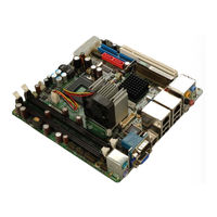
IEI Technology KINO-9455 User Manual (233 pages)
Intel Core 2 Duo/Core Duo/Core Solo Mini-ITX Dual PCIe GbE, SATA, USB 2.0, Two Independent Audio Streams, HDTV Output and 24-bit Dual-channel LVDS
Brand:
IEI Technology
| Category:
Motherboard
| Size: 7.76 MB
Table of Contents
Table of Contents
7
Introduction
19
Introduction
20
KINO-9455 Benefits
20
KINO-9455 Features
21
Kino-9455 Overview
22
KINO-9455 Overview Photo
22
Figure 1-1: KINO-9455 Overview [Front View]
22
KINO-9455 Peripheral Connectors and Jumpers
23
Technical Specifications
24
Table 1-1: Technical Specifications
25
Detailed Specifications
27
Overview
28
Dimensions
28
Board Dimensions
28
Figure 2-1: KINO-9455 Dimensions (MM)
28
External Interface Panel Dimensions
29
Figure 2-2: External Interface Panel Dimensions (MM)
29
Data Flow
30
Figure 2-3: Data Flow Block Diagram
30
Compatible Processors
31
Compatible Processor Overview
31
Figure 2-4: Socket M
31
Intel ® 945Gm Northbridge Chipset
32
Intel ® 945GM Overview
32
Figure 2-5: Socket M
32
Intel ® 945GM Memory Support
33
Figure 2-6: 240-Pin DDR2 DIMM Sockets
33
Intel ® 945GM Integrated Graphics
34
Intel ® 945GM VGA Support
34
Intel ® 945GM TV out Support
34
Figure 2-7: TV Out, VGA and LVDS
34
Chrontel CH7308A LVDS Support
35
Intel ® 945GM Direct Media Interface (DMI)
35
Intel ® Ich7-M Southbridge Chipset
36
Intel ® ICH7-M Overview
36
Figure 2-8: DMI Interface
36
Intel ® ICH7-M HD Audio Controller
38
Figure 2-9: HD Audio Codec
38
Intel ® ICH7-M IDE Interface
39
Figure 2-10: IDE Interface
39
Table 2-1: Supported HDD Specifications
39
Intel ® ICH7-M Low Pin Count (LPC) Interface
40
Intel ® ICH7-M PCI Interface
40
Figure 2-11: PCI Interface
40
Intel ® ICH7-M Real Time Clock
41
Intel ® ICH7-M SATA Controller
41
Intel ® ICH7-M Pcie X1 Bus: Pcie Gbe Controller
41
Figure 2-12: SATA Controller
41
Intel ® ICH7-M USB Controller
42
Figure 2-13: Pcie Gbe LAN Chipset and Connector
42
Lpc Bus Components
43
LPC Bus Overview
43
Figure 2-14: Onboard USB Implementation
43
BIOS Chipset
44
Figure 2-15: LPC Interface
44
Figure 2-16: BIOS Chipset
44
Fintek F81216D LPC Serial Port Chipset
45
Figure 2-17: Fintek F81286D Serial Port Chipset
45
Ite IT8712F Super I/O Chipset
46
Figure 2-18: Fintek F81286D Serial Port Chipset
46
Super I/O LPC Interface
47
Super I/O 16C550 Uarts
47
Super I/O Enhanced Hardware Monitor
47
Super I/O Fan Speed Controller
47
Super I/O GPIO Controller
47
Super I/O Keyboard/Mouse Controller
48
Environmental and Power Specifications
48
System Monitoring
48
Operating Temperature and Temperature Control
49
Power Consumption
50
Table 2-2: Power Consumption
50
Unpacking
51
Anti-Static Precautions
52
Unpacking
52
Unpacking Precautions
52
Unpacking Checklist
53
Package Contents
53
Table 3-1: Package List Contents
54
Connector Pinouts
55
Peripheral Interface Connectors
56
KINO-9455 Layout
56
Figure 4-1: Connector and Jumper Locations
56
Peripheral Interface Connectors
57
External Interface Panel Connectors
58
Table 4-1: Peripheral Interface Connectors
58
Table 4-2: Rear Panel Connectors
58
Internal Peripheral Connectors
59
ATX Power Connector
59
Figure 4-2: ATX Power Connector Pinout Locations
59
Audio Connector (9-Pin)
60
Figure 4-3: Audio Connector Location (9-Pin)
60
Table 4-3: ATX Power Connector Pinouts
60
Backlight Inverter Connector
62
Figure 4-4: Panel Backlight Connector Pinout Locations
62
Table 4-4: Audio Connector Pinouts (9-Pin)
62
Battery Connector
63
Figure 4-5: Battery Connector Location
63
Table 4-5: Panel Backlight Connector Pinouts
63
Digital Input/Output (DIO) Connector
64
Figure 4-6: DIO Connector Locations
64
Table 4-6: Battery Connector Pinouts
64
Fan Connector (+12V, 3-Pin)
65
Figure 4-7: +12V Fan Connector Location
65
Table 4-7: DIO Connector Connector Pinouts
65
Front Panel Connector (14-Pin)
66
Table 4-8: +12V Fan Connector Pinouts
66
IDE Connector (40-Pin)
67
Figure 4-8: Front Panel Connector Pinout Locations
67
Table 4-9: Front Panel Connector Pinouts
67
Figure 4-9: IDE Device Connector Locations
68
LVDS LCD Connector
69
Table 4-10: IDE Connector Pinouts
69
Figure 4-10: LVDS LCD Connector Pinout Locations
70
Table 4-11: LVDS LCD Port Connector Pinouts
70
Mini PCI Slot
71
Figure 4-11: Mini PCI Slot Location
72
PCI Slot
75
Table 4-12: Mini PCI Slot Pinouts
75
Figure 4-12: PCI Slot Location
76
Table 4-13: PCI Slot
78
SATA Drive Connectors
79
Figure 4-13: SATA Drive Connector Locations
79
Table 4-14: SATA Drive Connector Pinouts
79
Serial Port Connector (COM 2)(RS-232, RS-422 or RS-485)
80
Figure 4-14: RS-232/422/485 Serial Port Connector Location
80
Serial Port Connector (COM 3 and COM4)
81
Figure 4-15: COM3 and COM4 Connector Pinout Locations
81
Table 4-15: RS-232/RS-485 Serial Port Connector Pinouts
81
SPDIF Connector
82
Figure 4-16: SPDIF Connector Pinout Locations
82
Table 4-16: COM3 and COM4 Connector Pinouts
82
USB Connectors (Internal)
83
Figure 4-17: USB Connector Pinout Locations
83
Table 4-17: SPDIF Connector Pinouts
83
External Peripheral Interface Connector Panel
84
Figure 4-18: KINO-9455 External Peripheral Interface Connector
84
Table 4-18: USB Port Connector Pinouts
84
Audio Connector
85
Keyboard/Mouse Connector
85
Figure 4-19: Audio Connector
85
LAN Connectors
86
Figure 4-20: PS/2 Pinouts
86
Table 4-19: PS/2 Connector Pinouts
86
Serial Port Connectors (COM1 )
87
Figure 4-21: RJ-45 Ethernet Connector
87
Table 4-20: LAN Pinouts
87
Table 4-21: RJ-45 Ethernet Connector Leds
87
USB Connector
88
Figure 4-22: COM1 Pinout Locations
88
Table 4-22: RS-232 Serial Port (COM 1) Pinouts
88
TV Connector
89
Table 4-23: USB Port Pinouts
89
Table 4-24: TV Pinouts
89
VGA Connector
90
Figure 4-23: VGA Connector
90
Table 4-25: VGA Connector Pinouts
90
Installation
92
Anti-Static Precautions
93
Installation Considerations
94
Installation Notices
94
Installation Checklist
95
Cpu, Cpu Cooling Kit and DIMM Installation
96
Socket M CPU Installation
96
Figure 5-1: Make Sure the CPU Socket Retention Screw Is Unlocked
97
Figure 5-2: Lock the CPU Socket Retention Screw
98
Socket M CF-518-RS CPU Cooling Kit Installation
99
Figure 5-3: IEI CF-518-RS Cooling Kit
99
Figure 5-4: Securing the Cooling Kit
100
Figure 5-5: Cooling Fan Cable Connection
100
Cooling Kit CF-479B-RS Installation
101
Figure 5-6: IEI CF-479B-RS Cooling Kit
101
Figure 5-7: Cooling Kit Support Bracket
102
Figure 5-8: Connect the Cooling Fan Cable
102
DIMM Installation
103
Figure 5-9: Installing a DIMM
103
Jumper Settings
104
Figure 5-10: Jumper Locations
104
Clear CMOS Jumper
105
Table 5-1: Jumpers
105
Table 5-2: Clear CMOS Jumper Settings
105
LVDS Voltage Selection
106
Figure 5-11: Clear CMOS Jumper
106
RS-232/RS-422 or RS-485 Serial Port Select Jumper
107
Figure 5-12: LVDS Voltage Selection Jumper Pinout Locations
107
Table 5-3: LVDS Voltage Selection Jumper Settings
107
Chassis Installation
108
Airflow
108
Figure 5-13: RS-232/485 Serial Port Select Jumper Location
108
Table 5-4: RS-232/485 Serial Port Select Jumper Settings
108
Motherboard Installation
109
Internal Peripheral Device Connections
109
Peripheral Device Cables
109
ATA Flat Cable Connection
109
Table 5-5: IEI Provided Cables
109
Dual RS-232 Cable with Slot Bracket
110
Figure 5-14: IDE Cable Connection
110
SATA Drive Connection
111
Figure 5-15: Dual RS-232 Cable Installation
111
Figure 5-16: SATA Drive Cable Connection
112
External Peripheral Interface Connection
113
Figure 5-17: SATA Power Drive Connection
113
Audio Connection
114
LAN Connection (Single Connector)
114
Figure 5-18: Audio Connectors
114
PS/2 Keyboard and Mouse Connection
115
Figure 5-19: LAN Connection
115
Serial Device Connection
116
Figure 5-20: PS/2 Keyboard/Mouse Connector
116
S-Video Cable Connection
117
Figure 5-21: Serial Device Connector
117
USB Connection (Dual Connector)
118
Figure 5-22: S-Video Cable Connector
118
VGA Monitor Connection
119
Figure 5-23: USB Connector
119
Figure 5-24: VGA Connector
120
Ami Bios
122
Introduction
123
Starting Setup
123
Using Setup
123
Getting Help
124
Unable to Reboot after Configuration Changes
124
BIOS Menu Bar
124
Table 6-1: BIOS Navigation Keys
124
Main
125
Advanced
126
CPU Configuration
127
IDE Configuration
128
IDE Master, IDE Slave
130
Super IO Configuration
136
Hardware Health Configuration
139
ACPI Configuration
144
APM Configuration
145
Remote Access Configuration
148
USB Configuration
152
USB Mass Storage Device Configuration
155
Pci/Pnp
157
Boot
160
Boot Settings Configuration
160
Boot Device Priority
163
Hard Disk Drives
164
CD/DVD Drives
166
Security
168
Chipset
169
Northbridge Configuration
171
Southbridge Sis964 Configuration
175
Exit
176
Driver Installation
180
Available Software Drivers
181
Driver CD Auto-Run
181
Figure 7-1: Introduction Screen
182
Intel ® Chipset Driver Installation
183
Figure 7-2: Available Drivers
183
Figure 7-3: Chipset Driver Installation Program
184
Figure 7-4: Chipset Driver Installation Welcome Screen
184
Figure 7-5: Chipset Driver Installation License Agreement
185
Figure 7-6: Chipset Driver Readme File Information
185
Intel ® Graphics Media Accelerator Driver Installation
186
Figure 7-7: Chipset Driver Installation Complete
186
Figure 7-8: Select the Operating System
187
Figure 7-9: VGA Driver
187
Figure 7-10: Intel® Graphics Media Accelerator Installshield Wizard
188
Figure 7-11: Installshield Wizard Extracting Files
188
Figure 7-12: Intel® Graphics Media Accelerator Driver Welcome Screen
189
Figure 7-13: Intel® Graphics Media Accelerator Driver License Agreement
189
Broadcom LAN Driver (for Gbe LAN) Installation
190
Figure 7-14: Intel® Graphics Media Accelerator Driver Installing Notice
190
Figure 7-15: Intel® Graphics Media Accelerator Installation Complete
190
Figure 7-16: Windows Control Panel
191
Figure 7-17: System Icon
191
Figure 7-18: Device Manager Tab
192
Figure 7-19: Device Manager List
193
Figure 7-20: Search for Suitable Driver
194
Figure 7-21: Locate Driver Files
194
Realtek Hd Audio Driver (Alc883) Installation
195
BIOS Setup
195
Driver Installation
195
Figure 7-22: Location Browsing Window
195
Figure 7-23: Select the Audio CODEC
196
Figure 7-24: Select the os
197
Figure 7-25: Select the os Version
197
Figure 7-26: Locate the Setup Program Icon
198
Figure 7-27: the Installshield Wizard Starts
198
Figure 7-28: Preparing Setup Screen
199
Figure 7-29: Installshield Wizard Welcome Screen
199
Figure 7-30: Audio Driver Software Configuration
200
Figure 7-31: Installation Wizard Updates the System
200
Figure 7-32: Restart the Computer
201
Abios Options
202
Bterminology
206
Cdio Interface
212
Dio Interface Introduction
213
Gpio Connector Pinouts
213
Assembly Language Samples
214
Enable the DIO Input Function
214
Enable the DIO Output Function
214
Dwatchdog Timer
216
Eaddress Mapping
220
Address Map
221
St Mb Memory Address Map
221
Irq Mapping Table
222
Dma Channel Assignments
222
Hazardous Materials Disclosure
224
Hazardous Material Disclosure Table for IPB Products Certified as Rohs Compliant under 2002/95/EC Without Mercury
225
Gindex
228
Advertisement
Advertisement
Related Products
IEI Technology KINO-9453
IEI Technology KINO-945GSE
IEI Technology KINO-945GSE3
IEI Technology KINO-945GSE2
IEI Technology KINO-9454
IEI Technology KINO-9451
IEI Technology KINO-9452
IEI Technology KINO-9653
IEI Technology Kino-9654G4
IEI Technology KINO-9152G4
IEI Technology Categories
Motherboard
Touch Panel
Computer Hardware
Single board computers
Desktop
More IEI Technology Manuals
Login
Sign In
OR
Sign in with Facebook
Sign in with Google
Upload manual
Upload from disk
Upload from URL