Sign In
Upload
Manuals
Brands
IEI Technology Manuals
Motherboard
KINO-945GSE
IEI Technology KINO-945GSE Manuals
Manuals and User Guides for IEI Technology KINO-945GSE. We have
2
IEI Technology KINO-945GSE manuals available for free PDF download: User Manual, Quick Installation Manual
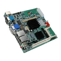
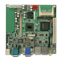
IEI Technology KINO-945GSE User Manual (190 pages)
Mini-ITX Motherboard with 45 nm Intel Atom CPU DDR2 Memory (up to 2 GB), VGA, DVI, LVDS, HDTV Dual PCIe GbE, CompactFlash, Dual SATA and PCIe Mini
Brand:
IEI Technology
| Category:
Motherboard
| Size: 12.58 MB
Table of Contents
Packing List
4
Table of Contents
5
1 Introduction
17
Introduction
18
Kino-945Gse Overview
18
Overview Photo
18
Figure 1-1: KINO-945GSE
18
Peripheral Connectors and Jumpers
19
Figure 1-2: KINO-945GSE Overview
19
Technical Specifications
20
Table 1-1: Technical Specifications
22
2 Detailed Specifications
23
Dimensions
24
Board Dimensions
24
Figure 2-1: KINO-945GSE Dimensions (MM)
24
External Interface Panel Dimensions
25
Figure 2-2: External Interface Panel Dimensions (MM)
25
Data Flow
26
Figure 2-3: Data Flow Block Diagram
26
Embedded Intel® Atom™ Processor
27
Overview
27
Features
27
Figure 2-4: Intel® Atom™ N270 CPU
27
Front Side Bus (FSB)
28
Figure 2-5: Front Side Bus
28
Intel® 945GSE Northbridge Chip
29
DDR2 Controller
29
Figure 2-6: Intel® 945GSE Northbridge Chip
29
Graphics
30
Figure 2-7: DDR2 SO-DIMM Socket
30
Analog CRT (VGA)
31
Figure 2-8: Graphics
31
Lvds
31
TV out
31
SDVO and DVI
32
Intel® ICH7M Southbridge Chipset
32
Figure 2-9: Intel® ICH7M Southbridge Chipset
33
Audio Codec '97 Controller
34
IDE Interface
34
IDE Connector
34
Figure 2-10: IDE Connector
34
Compactflash® Slot
35
Table 2-1: Supported HDD Specifications
35
Low Pin Count (LPC) Interface
36
PCI Bus
36
Figure 2-11: Compactflash® Slot
36
PCI Expansion Card Slot
37
Pcie Bus
37
Pcie Gbe Ethernet
37
Figure 2-12: PCI Edge Connector
37
Figure 2-13: Realtek PCI Gbe Controllers
38
Pcie Mini Card
39
Figure 2-14: Pcie Mini Card Slot
39
Real Time Clock
39
Figure 2-15: SATA Connectors
40
SATA Controller
40
USB Controller
40
Lpc Bus Components
41
Figure 2-16: Onboard USB Implementation
41
BIOS Chipset
42
Ite IT8718F Super I/O Chipset
42
Figure 2-17: LPC Bus
42
16C550 Uarts
43
Digital Input/Output
43
Enhanced Hardware Monitor
43
Fan Speed Controller
43
LPC Interface
43
Keyboard/Mouse Controller
44
Parallel Port
44
Fintek F81216D LPC Serial Port Chipset
44
Environmental and Power Specifications
44
System Monitoring
44
Operating Temperature and Temperature Control
45
Power Consumption
46
Table 2-2: Power Consumption
46
3 Unpacking
47
Anti-Static Precautions
48
Unpacking
48
Unpacking Precautions
48
Unpacking Checklist
49
Package Contents
49
Optional Items
50
Table 3-1: Packing List
50
Table 3-2: Power Consumption
50
4 Connectors
51
Peripheral Interface Connectors
52
Layout
52
Figure 4-1: Connector and Jumper Locations [Front Side]
52
Internal Peripheral Interface Connectors
53
External Interface Panel Connectors
54
Table 4-1: Peripheral Interface Connectors
54
Internal Peripheral Connectors
55
ATX Power Connector
55
Figure 4-2: ATX Power Connector Pinout Locations
55
Table 4-2: Rear Panel Connectors
55
Battery Connector
56
Table 4-3: ATX Power Connector Pinouts
56
Compactflash® Socket
57
Figure 4-3: Battery Connector Location
57
Table 4-4: Battery Connector Pinouts
57
Figure 4-4: CF Card Socket Location
58
Digital I/O Connector
59
Figure 4-5: Digital I/O Connector Locations
59
Table 4-5: CF Card Socket Pinouts
59
Fan Connector
60
Table 4-6: DIO Connector Pinouts
60
Front Panel Connector
61
Figure 4-6: CPU Fan Connector Location
61
Table 4-7: CPU Fan Connector Pinouts
61
IDE Connector
62
Figure 4-7: Front Panel Connector Pinout Locations
62
Table 4-8: Front Panel Connector Pinouts
62
Figure 4-8: IDE Device Connector Locations
63
Infrared Interface Connector
64
Figure 4-9: Infrared Connector Pinout Locations
64
Table 4-9: IDE Connector Pinouts
64
LCD Backlight Inverter Connector
65
Figure 4-10: LCD Backlight Connector Pinout Locations
65
Table 4-10: Infrared Connector Pinouts
65
LVDS LCD Connector
66
Figure 4-11: LVDS LCD Connector Pinout Locations
66
Table 4-11: LCD Backlight Connector Pinouts
66
Pcie Mini Card Slot
67
Table 4-12: LVDS LCD Port Connector Pinouts
67
Figure 4-12: Pcie Mini Card Slot Location
68
SATA Drive Connectors
69
Table 4-13: Pcie Mini Card Slot Pinouts
69
Serial Port Connectors (RS-232)
70
Figure 4-13: SATA Drive Connector Locations
70
Table 4-14: SATA Drive Connector Pinouts
70
Serial Port Connectors (RS-422/485)
71
Figure 4-14: RS-232 Connector Pinout Locations
71
Table 4-15: RS-232 Connector Pinouts
71
Figure 4-15: RS-422/485 Connector Pinout Locations
72
Table 4-16: RS-422/485 Connector Pinouts
72
TV out Connector
73
Figure 4-16: TV Connector Pinout Locations
73
USB Connectors
74
Figure 4-17: USB Connector Pinout Locations
74
Table 4-17: TV Port Connector Pinouts
74
External Peripheral Interface Connector Panel
75
Audio Connector
75
Figure 4-18: KINO-945GSE External Peripheral Interface Connector
75
Table 4-18: USB Port Connector Pinouts
75
Keyboard/Mouse Connector
76
Figure 4-19: Audio Connector
76
Figure 4-20: PS/2 Pinouts
76
DVI Connector
77
LAN Connectors
77
Table 4-19: PS/2 Connector Pinouts
77
Table 4-20: DVI Connector Pinouts
77
Serial Port Connectors
78
Figure 4-21: RJ-45 Ethernet Connector
78
Table 4-21: LAN Pinouts
78
Table 4-22: RJ-45 Ethernet Connector Leds
78
USB Connectors
79
Figure 4-22: RS-232 Serial Port Pinout Locations
79
Table 4-23: RS-232 Serial Port Pinouts
79
VGA Connector
80
Figure 4-23: VGA Connector
80
Table 4-24: USB Port Pinouts
80
Table 4-25: VGA Connector Pinouts
80
5 Installation
81
Anti-Static Precautions
82
Installation Considerations
83
Installation Notices
83
Installation Checklist
84
Unpacking
84
So-DIMM Installation
85
Figure 5-1: SO-DIMM Installation
85
Cf Card Installation
86
Jumper Settings
87
Figure 5-2: CF Card Installation
87
AT/ATX Selection
88
Table 5-1: Jumpers
88
Table 5-2: AT/ATX Power Selection Jumper Settings
88
Clear CMOS Jumper
89
Figure 5-3: AT/ATX Power Selection Jumper Location
89
CF Card Setup
90
Figure 5-4: Clear CMOS Jumper
90
Table 5-3: Clear CMOS Jumper Settings
90
Table 5-4: CF Card Setup Jumper Settings
90
COM3 RS-232/422/485 Selection Jumper
91
Figure 5-5: CF Card Setup Jumper Location
91
Table 5-5: COM3 RS-232/422/485 Selection Jumper Pinouts
91
Figure 5-6: COM3 RS-232/422/485 Selection Jumper Location
92
LCD Panel Type Selection
92
Table 5-6: LCD Panel Type Selection Jumper Settings
92
Figure 5-7: LCD Panel Type Selection Jumper Pinout Locations
93
LVDS Voltage Selection
93
Chassis Installation
94
Airflow
94
Figure 5-8: LVDS Voltage Selection Jumper Pinout Locations
94
Table 5-7: LVDS Voltage Selection Jumper Settings
94
Motherboard Installation
95
Internal Peripheral Device Connections
95
Table 5-8: IEI Provided Cables
95
ATA Flat Cable Connection
96
Figure 5-9: IDE Cable Connection
96
Figure 5-10: SATA Drive Cable Connection
97
SATA Drive Connection
97
Dual RS-232 Cable with Slot Bracket
98
Figure 5-11: SATA Power Drive Connection
98
Figure 5-12: Dual RS-232 Cable Installation
99
USB Cable (Dual Port) with Slot Bracket
99
Figure 5-13: Dual USB Cable Connection
100
External Peripheral Interface Connection
101
LAN Connection (Single Connector)
101
PS/2 Y-Cable Connection
102
Figure 5-14: LAN Connection
102
Serial Device Connection
103
Figure 5-15: PS/2 Keyboard/Mouse Connector
103
USB Connection (Dual Connector)
104
Figure 5-16: Serial Device Connector
104
VGA Monitor Connection
105
Figure 5-17: USB Connector
105
Figure 5-18: VGA Connector
106
6 Bios Setup
107
Introduction
108
Starting Setup
108
Using Setup
108
Getting Help
109
Unable to Reboot after Configuration Changes
109
BIOS Menu Bar
109
Table 6-1: BIOS Navigation Keys
109
Main
110
Advanced
111
CPU Configuration
113
IDE Configuration
114
IDE Master, IDE Slave
116
Super IO Configuration
121
Hardware Health Configuration
124
Power Configuration
128
APM Configuration
129
Remote Configuration
132
USB Configuration
136
Pci/Pnp
137
Boot
140
Boot Settings Configuration
141
Boot Device Priority
143
Security
143
Chipset
144
Northbridge Chipset Configuration
146
Southbridge Configuration
149
Exit
150
7 Software Installation
152
Available Software Drivers
153
Starting the Driver Program
153
Figure 7-1: Start up Screen
154
Figure 7-2: Select Operating System
154
Chipset Driver Installation
155
Figure 7-3: Drivers
155
Figure 7-4: Chipset Driver Welcome Screen
156
Figure 7-5: Chipset Driver License Agreement
156
Figure 7-6: Chipset Driver Read Me File
157
Figure 7-7: Chipset Driver Setup Operations
157
Vga Driver Installation
158
Figure 7-8: Chipset Driver Installation Finish Screen
158
Figure 7-9: VGA Driver Read Me File
159
Figure 7-10: VGA Driver Setup Files Extracted
159
Figure 7-11: VGA Driver Welcome Screen
160
Figure 7-12: VGA Driver License Agreement
160
Figure 7-13: VGA Driver Read Me File
161
Figure 7-14: VGA Driver Setup Operations
162
Figure 7-15: VGA Driver Installation Finish Screen
162
Lan Driver Installation
163
Figure 7-16: LAN Driver Welcome Screen
163
Figure 7-17: LAN Driver Welcome Screen
164
Figure 7-18: LAN Driver Installation
164
Audio Driver Installation
165
Figure 7-19: LAN Driver Installation Complete
165
Figure 7-20: Audio Driver Options
166
Figure 7-21: AC'97 Driver Installation Welcome Screen
166
Figure 7-22: AC'97 Driver Installation Verification
167
Figure 7-23: AC'97 Driver Installation Complete
167
ABIOS Options
168
B Terminology
172
C Digital I/O Interface
176
Introduction
177
Dio Connector Pinouts
177
C.1 I Ntroduction
177
C.2 Dio C Onnector P Inouts
177
Assembly Language Samples
178
C.3 a Ssembly L Anguage S Amples
178
Enable the DIO Input Function
178
Enable the DIO Output Function
178
D Watchdog Timer
179
E Address Mapping
182
Direct Memory Access (Dma)
183
Input/Output (IO)
183
E.1 D Irect M Emory a Ccess (Dma)
183
E.2 I Nput /O Utput (Io)
183
Advertisement
IEI Technology KINO-945GSE Quick Installation Manual (13 pages)
Mini-ITX Motherboard
Brand:
IEI Technology
| Category:
Motherboard
| Size: 0.13 MB
Advertisement
Related Products
IEI Technology KINO-9453
IEI Technology KINO-945GSE3
IEI Technology KINO-945GSE2
IEI Technology KINO-9454
IEI Technology KINO-9451
IEI Technology KINO-9452
IEI Technology KINO-9455
IEI Technology KINO-9653
IEI Technology Kino-9654G4
IEI Technology KINO-9152G4
IEI Technology Categories
Motherboard
Touch Panel
Computer Hardware
Single board computers
Desktop
More IEI Technology Manuals
Login
Sign In
OR
Sign in with Facebook
Sign in with Google
Upload manual
Upload from disk
Upload from URL