Sign In
Upload
Manuals
Brands
IEI Technology Manuals
Motherboard
KINO-9451
IEI Technology KINO-9451 Motherboard Manuals
Manuals and User Guides for IEI Technology KINO-9451 Motherboard. We have
1
IEI Technology KINO-9451 Motherboard manual available for free PDF download: User Manual
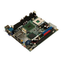
IEI Technology KINO-9451 User Manual (212 pages)
Mini-ITX Motherboard with Intel Core 2 Duo CPU with VGA/DVi, Dual GbE, USB 2.0, SATA, Audio and PCIe x16 Expansion
Brand:
IEI Technology
| Category:
Motherboard
| Size: 6 MB
Table of Contents
Packing List
6
Table of Contents
7
1 Introduction
19
Figure 1-1: KINO-9451 Embedded SBC
20
Figure 1-2: KINO-9451 Board Overview (Top View)
22
Technical Specifications
24
Kino-9451 Overview
20
KINO-9451 Benefits
21
KINO-9451 Features
21
Kino-9451 Board Overview
22
KINO-9451 Connectors
22
Table 1-1: Technical Specifications
25
2 Detailed Specifications
26
Dimensions
27
Board Dimensions
27
External Interface Panel Dimensions
27
Figure 2-1: KINO-9451 Dimensions (MM)
27
Figure 2-2: External Interface Panel Dimensions (MM)
28
Figure 2-3: Data Flow Block Diagram
29
Supported Processors
30
Table 2-1: Processor Features
30
Intel ® 945Gme Graphics and Memory Controller Hub
31
Intel ® 945GME Memory Support
31
Intel ® 945GME Overview
31
Table 2-2: Supported Processors
31
Intel ® 945GME Pcie X16
32
Pcie X16 Bus Overview
32
Compatible Processors
29
Compatible Processor Overview
29
Overview
27
Data Flow
28
Figure 2-4: 240-Pin DDR2 DIMM Sockets
32
Figure 2-5: Pcie X16 Socket
33
Intel ® 945GME Integrated Graphics
33
Pcie X16 Bus Specifications
33
Intel 945GME Analog CRT Support
34
Intel 945GME LVDS Support
34
Intel 945GME TV out Support
34
Intel ® 945GME Direct Media Interface (DMI)
35
Intel ® Ich7-M I/O Controller Hub
35
Intel ® ICH7-M Overview
35
Figure 2-6: HD Audio Codec
36
Intel ® ICH7-M HD Audio Controller
36
Intel ® ICH7-M Pcie Bus: Pcie Gbe Ethernet Controller
36
Figure 2-7: Pcie Gbe Connectors
37
Figure 2-8: Mini PCI Slot
38
Figure 2-9: Onboard USB Implementation
40
Pcie Bu Component
40
BIOS Chipset
41
Lpc Bus Components
41
LPC Bus Overview
41
Super I/O Chipset
41
Super I/O 16C550 Uarts
42
Super I/O LPC Interface
42
Fintek F81216DG LPC Serial Port Chipset
43
Super I/O Enhanced Hardware Monitor
43
Super I/O Fan Speed Controller
43
Super I/O Keyboard Controller
43
Environmental and Power Specifications
44
Operating Temperature and Temperature Control
44
System Monitoring
44
Power Consumption
45
Intel ® ICH7-M Low Pin Count (LPC) Interface
38
Intel ® ICH7-M PCI Interface
38
Intel ICH7-M Real Time Clock
39
Intel ® ICH7-M SATA Controller
39
Intel ® ICH7-M USB Controller
39
Pcie Bus Components
40
Broadcom PCI Express Gbe Interface
40
Pcie Bus Overview
40
Pcie X16 Expansion
40
ICH7-M IDE Interface
37
Table 2-3: Supported HDD Specifications
37
Table 2-4: Power Consumption
45
Table 2-5: Power Consumption
45
3 Unpacking
46
Anti-Static Precautions
47
Unpacking
47
Unpacking Precautions
47
Unpacking Checklist
48
Package Contents
48
Optional Items
49
Table 3-1: Package List Contents
49
Table 3-2: Optional Items
50
4 Connectors and Jumpers
51
Figure 4-1: Connector and Jumper Locations
52
Peripheral Interface Connectors
52
KINO-9451 Layout
52
Peripheral Interface Connectors
53
Rear Panel Connectors
54
Table 4-2: Rear Panel Connectors
54
Table 4-1: Peripheral Interface Connectors
54
Figure 4-2: Audio Connector Location
55
Table 4-4: GPIO Connector Pinouts
56
Fan Connectors
57
Table 4-3: Audio Connector Pinouts
55
Digital Input/Output Connector
56
Internal Peripheral Connectors
55
Audio Connector
55
Figure 4-3: GPIO Connector Location
56
Figure 4-4: Fan Connector Locations
57
Figure 4-5: Front Panel Connector Location
58
Front Panel Connector
58
Table 4-5: Fan Connector Pinouts
58
IDE Connector
59
Table 4-6: Front Panel Connector Pinouts
59
Figure 4-14: Power Button Connector Location
71
Figure 4-15: 14-Pin Serial Port Connector Locations
72
Table 4-17: COM5 Pinouts
72
Figure 4-16: 10-Pin Serial Port Connector Locations
73
Figure 4-17: SATA Drive Connector Locations
74
SPDIF Connector
74
SATA Drive Connectors
73
Table 4-18: COM3 and COM4 Pinouts
73
Table 4-19: SATA Drive Connector Pinouts
74
Figure 4-18: SPDIF Connector Locations
75
Internal USB Connectors
75
Table 4-20: SPDIF Pinouts
75
External Interface Connectors
76
Figure 4-19: Internal USB Connector Locations
76
Table 4-21: USB3 and USB4 Pinouts
76
Audio Connectors
77
Figure 4-20: KINO-9451 External Interface Connectors
77
CRT Connector
78
Figure 4-21: Audio Connectors
78
Figure 4-22: VGA Connector
78
Ethernet Connectors
79
Figure 4-23: RJ-45 Ethernet Connector
79
Table 4-22: VGA Connector Pinouts
79
Table 4-23: LAN1 and LAN2 Pinouts
79
Figure 4-24: PS/2 Pinouts
80
Keyboard/Mouse Connector
80
Table 4-24: RJ-45 Ethernet Connector Leds
80
Figure 4-25: External Serial Port Connector
81
Serial Port Connectors
81
Table 4-25: PS/2 Connector Pinouts
81
Table 4-26: External Serial Port Pinouts
82
TV-Out Connector
82
USB Connector
83
Figure 4-6: IDE Device Connector Location
60
Figure 4-7: Infrared Connector Pinout Locations
61
Infrared Interface Connector
61
Table 4-8: Infrared Connector Pinouts
61
Figure 4-8: LCD Backlight Connector Location
62
Figure 4-9: LVDS LCD Connector Location
63
LVDS LCD Connector
63
Table 4-7: IDE Connector Pinouts
61
LCD Backlight Connector
62
Table 4-9: LCD Backlight Connector Pinouts
62
Figure 4-10: Mini PCI Slot Location
64
Mini PCI Slot
64
Table 4-10: LVDS LCD Connector Pinouts
64
Table 4-11: Mini PCI Slot Pinouts
65
Figure 4-11: Panel ID Connector Location
66
Figure 4-12: Pcie X16 Connector Location
67
PCI Express X16 Slot
67
Panel ID Connector
66
Table 4-12: Panel ID Connector Pinouts
66
Table 4-13: Pcie X16 Side a Pinouts
68
Figure 4-13: Power Connector Location
69
Power Connector
69
Table 4-14: Pcie X16 Side B Pinouts
69
Power Button Connector
70
Table 4-15: Power Connector Pinouts
70
14-Pin Serial Port Connectors
71
Table 4-16: Power Button Connector Pinouts
71
10-Pin Serial Port Connectors
72
Figure 4-26: TV-Out Connector
82
Table 4-27: TV-Out Pinouts
83
Table 4-28: External USB Connector Pinouts
83
5 Installation
84
Anti-Static Precautions
85
Installation Considerations
86
Installation Notices
86
Installation Checklist
87
Cpu, Cpu Cooling Kit and DIMM Installation
88
Socket 479 CPU Installation
88
Figure 5-1: Make Sure the CPU Socket Retention Screw Is Unlocked
89
Cooling Kit CF-479B-RS Installation
90
Figure 5-3: IEI CF-479B-RS Cooling Kit
90
Figure 5-5: Connect the Cooling Fan Cable
92
Figure 5-6: Installing a DIMM
93
Table 5-1: Jumpers
94
Clear CMOS Jumper
95
Jumper Settings
94
AT/ATX Power Select Jumper Settings
94
Figure 5-2: Lock the CPU Socket Retention Screw
90
Figure 5-4: Cooling Kit Support Bracket
91
DIMM Installation
92
Figure 5-7: Jumper Locations
94
Figure 5-9: Clear CMOS Jumper
97
Figure 5-10: COM 5 Function Select Jumper Location
98
Or RS-486 Termination Resister
98
Table 5-5: RS-485 Termination Resister Jumper Settings
98
Figure 5-11: RS-422 and RS-485 Termination Resister Jumper Locations
99
LVDS Voltage Selection
99
Table 5-6: RS-422 Termination Resister Jumper Settings
99
Figure 5-12: LVDS Voltage Selection Jumper Pinout Locations
100
Table 5-7: LVDS Voltage Selection Jumper Settings
100
Airflow
101
Chassis Installation
101
Motherboard Installation
101
IDE Cable Connection
102
Internal Peripheral Device Connections
102
Peripheral Device Cables
102
Table 5-8: IEI Provided Cables
102
Dual RS-232 Cable Connection
103
Figure 5-13: IDE Cable Connection
103
Figure 5-14: Dual RS-232 Cable Installation
104
SATA Drive Connection
104
Figure 5-15: SATA Drive Cable Connection
105
External Peripheral Interface Connection
106
Figure 5-16: SATA Power Drive Connection
106
Audio Connection
107
Ethernet and USB Connection
107
Figure 5-17: Audio Connectors
107
Figure 5-18: RJ-45 Ethernet Connector
108
VGA Monitor Connection
108
Figure 5-19: VGA Connector
109
Serial Device Connection
109
PS/2 Keyboard/Mouse Connection
110
Table 5-4: COM 5 Function Select Jumper Settings
98
Table 5-2: AT/ATX Power Select Jumper Settings
95
Figure 5-8: AT/ATX Power Select Jumper Location
95
Table 5-3: Clear CMOS Jumper Settings
96
COM 5 Function Select Jumper
97
Figure 5-20: Serial Device Connector
110
Figure 5-21: PS/2 Keyboard/Mouse Connector
111
6 Ami Bios
112
Introduction
113
Starting Setup
113
Using Setup
113
Getting Help
114
Unable to Reboot after Configuration Changes
114
BIOS Menu Bar
114
Table 6-1: BIOS Navigation Keys
114
Main
115
Advanced
116
CPU Configuration
117
IDE Configuration
118
Menu 4: IDE Configuration
119
IDE Master, IDE Slave
120
Menu 5: IDE Master and IDE Slave Configuration
121
Super IO Configuration
125
Hardware Health Configuration
128
Menu 7: Hardware Health Configuration
129
ACPI Configuration
130
APM Configuration
131
Remote Access Configuration
133
USB Configuration
137
USB Mass Storage Device Configuration
139
Pci/Pnp
141
Menu 13: Pci/Pnp Configuration
142
Boot
144
Boot Settings Configuration
144
Menu 15: Boot Settings Configuration
145
Boot Device Priority
147
Hard Disk Drives
148
Security
149
Menu 18: Security
150
Chipset
151
Northbridge Configuration
152
Video Function Configuration
153
Southbridge Configuration
155
Exit
156
Menu 22:Exit
157
7 Software Driver
159
Available Software Drivers
160
Chipset Driver Installation
160
Figure 7-2: Welcome Screen
161
Figure 7-4: Readme Information
162
Figure 7-5: Restart the Computer
163
Figure 7-12: Access Windows Control Panel
167
Figure 7-13: Double Click the System Icon
168
Figure 7-14: Double Click the Device Manager Tab
168
Figure 7-19: Access Windows Control Panel
172
Figure 7-20: Double Click the System Icon
173
Figure 7-21: Double Click the Device Manager Tab
174
Figure 7-22: Device Manager List
175
Figure 7-23: Search for Suitable Driver
176
Intel Matrix Storage Manager Installation
177
Figure 7-1: Installshield Wizard Preparation Screen
161
Figure 7-3: License Agreement
162
Figure 7-15: Device Manager List
169
Figure 7-16: Search for Suitable Driver
170
Figure 7-18: Location Browsing Window
171
Figure 7-17: Locate Driver Files
171
Realtek HD Audio Driver (ALC883) Installation
172
Vga Driver
163
Figure 7-6: Starting Install Shield Wizard Screen
164
Figure 7-7: Preparing Setup Screen
164
Figure 7-8: VGA Driver Installation Welcome Screen
165
Figure 7-9: VGA Driver License Agreement
165
Figure 7-10: VGA Driver Installing Notice
166
Figure 7-11: VGA Driver Installation Complete
166
Broadcom LAN Driver (for Gbe LAN) Installation
167
Figure 7-24: Locate Driver Files
177
Figure 7-25: Preparing Setup Screen
178
Abios Configuration Options
180
Bios Configuration Options
180
A.1 Bios C Onfiguration O Ptions
181
Bdio Interface
184
Dio Interface Introduction
185
Dio Connector Pinouts
185
B.1 Dio I Nterface I Ntroduction
185
Assembly Language Samples
186
Enable the DIO Input Function
186
Enable the DIO Output Function
186
Cwatchdog Timer
187
Daddress Mapping
190
Io Address Map
191
St Mb Memory Address Map
191
Addres Map
191
Irq Mapping Table
192
Dma Channel Assignments
192
Ecompatibility
193
Compatible Processors
194
Compatible Memory Modules
194
Hazardous Materials Disclosure
196
Hazardous Material Disclosure Table for Ipb Products Certified as R Ohs Compliant under 2002/95/Ec Without Mercury
197
Gasf Function
200
Introduction
201
Client Configuration
201
Management Console Configuration
205
Hindex
207
Advertisement
Advertisement
Related Products
IEI Technology KINO-9453
IEI Technology KINO-945GSE
IEI Technology KINO-945GSE3
IEI Technology KINO-945GSE2
IEI Technology KINO-9454
IEI Technology KINO-9452
IEI Technology KINO-9455
IEI Technology KINO-9653
IEI Technology Kino-9654G4
IEI Technology KINO-9152G4
IEI Technology Categories
Motherboard
Touch Panel
Computer Hardware
Single board computers
Desktop
More IEI Technology Manuals
Login
Sign In
OR
Sign in with Facebook
Sign in with Google
Upload manual
Upload from disk
Upload from URL