Sign In
Upload
Manuals
Brands
IEI Technology Manuals
Motherboard
KINO-QM670
User Manuals: IEI Technology KINO-QM670 Motherboard
Manuals and User Guides for IEI Technology KINO-QM670 Motherboard. We have
1
IEI Technology KINO-QM670 Motherboard manual available for free PDF download: User Manual
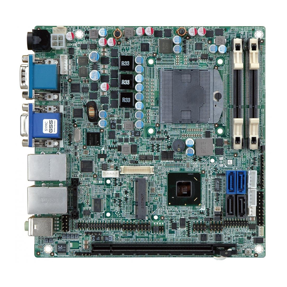
IEI Technology KINO-QM670 User Manual (186 pages)
Mini-ITX Motherboard Supports Socket G2 for Intel Mobile Core i7/i5 CPU, VGA/LVDS/HDMI Dual GbE, USB 3.0, PCIe Mini, SATA 6Gb/s and Audio
Brand:
IEI Technology
| Category:
Motherboard
| Size: 9.19 MB
Table of Contents
User Manual
1
Table of Contents
4
1 Introduction
16
Introduction
17
Figure 1-1: KINO-QM670
17
Connectors
18
Figure 1-2: Connectors
18
Dimensions
19
Board Dimensions
19
Figure 1-3: KINO-QM670 Dimensions (MM)
19
External Interface Panel Dimensions
20
Figure 1-4: External Interface Panel Dimensions (MM)
20
Data Flow
21
Figure 1-5: Data Flow Block Diagram
21
Technical Specifications
22
Table 1-1: Technical Specifications
23
2 Unpacking
24
Anti-Static Precautions
25
Unpacking Precautions
25
Packing List
26
Optional Items
27
3 Connectors
28
Peripheral Interface Connectors
29
KINO-QM670 Layout
29
Figure 3-1: Connector and Jumper Locations
29
Peripheral Interface Connectors
30
External Interface Panel Connectors
31
Table 3-1: Peripheral Interface Connectors
31
Table 3-2: Rear Panel Connectors
31
Internal Peripheral Connectors
32
Audio Connector
32
Figure 3-2: Audio Connector Location
32
Table 3-3: Audio Connector Pinouts
32
Battery Connector
33
Figure 3-3: Battery Connector Location
33
Table 3-4: Battery Connector Pinouts
33
Backlight Inverter Connector
34
Figure 3-4: Panel Backlight Connector Pinout Location
34
Table 3-5: Panel Backlight Connector Pinouts
34
Digital I/O Connector
35
Figure 3-5: Digital I/O Connector Location
35
Table 3-6: Digital I/O Connector Pinouts
35
EC Debug Port
36
Figure 3-6: BIOS Debug Port Location
36
Table 3-7: EC Debug Port Pinouts
36
Fan Connector (CPU)
37
Fan Connector (System)
37
Figure 3-7: CPU Fan Connector Location
37
Table 3-8: CPU Fan Connector Pinouts
37
Front Panel Connector
38
Figure 3-8: +12V Fan Connector Location
38
Table 3-9: +12V Fan Connector Pinouts
38
Infrared Interface Connector
39
Figure 3-9: Front Panel Connector Location
39
Table 3-10: Front Panel Connector Pinouts
39
Keyboard/Mouse Connector
40
Figure 3-10: Infrared Connector Location
40
Table 3-11: Infrared Connector Pinouts
40
LVDS Connector
41
Figure 3-11: Keyboard/Mouse Connector Location
41
Table 3-12: Keyboard/Mouse Connector Pinouts
41
Figure 3-12: LVDS LCD Connector Pinout Location
42
Table 3-13: LVDS LCD Port Connector Pinouts
42
Pcie Mini Card Slot
43
Figure 3-13: Pcie Mini Card Slot Location
43
Power Connector
44
Table 3-14: Pcie Mini Card Slot Pinouts
44
SATA Drive Connectors
45
Figure 3-14: CPU 12V Power Connector Location
45
Table 3-15: CPU 12V Power Connector Pinouts
45
SATA Power Connector
46
Figure 3-15: SATA Drive Connector Location
46
Table 3-16: SATA Drive Connector Pinouts
46
Serial Port Connector (RS-232)
47
Figure 3-16: SATA Power Connector Location
47
Table 3-17: SATA Power Connector Pinouts
47
Serial Port Connectors (RS-422/485)
48
Figure 3-17: Serial Port Connector Location
48
Table 3-18: Serial Port Connector Pinouts
48
Smbus Connector
49
Figure 3-18: Serial Port Connector (RS-422/485) Location
49
Table 3-19: Serial Port Connector (RS-422/485) Pinouts
49
Table 3-20: DB-9 RS-422/485 Pinouts
49
SPDIF Connector
50
Figure 3-19: Smbus Connector Location
50
Table 3-21: Smbus Connector Pinouts
50
SPI Flash Connector
51
Figure 3-20: SPDIF Connector Location
51
Table 3-22: SPDIF Connector Pinouts
51
TPM Connector
52
Figure 3-21: SPI Flash Connector Location
52
Table 3-23: JSPI1 Flash Connector Pinouts
52
Table 3-24: JSPI2 Flash Connector Pinouts
52
USB Connectors
53
Figure 3-22: TPM Connector Pinout Location
53
Table 3-25: TPM Connector Pinouts
53
External Peripheral Interface Connector Panel
54
Figure 3-23: USB Connector Pinout Location
54
Table 3-26: USB Port Connector Pinouts
54
Audio Connector
55
Figure 3-24: KINO-QM670 External Peripheral Interface Connector
55
Figure 3-25: Audio Jacks
55
Ethernet and USB 2.0 Connector
56
Figure 3-26: Ethernet Connector
56
Table 3-27: LAN Pinouts
56
Table 3-28: Ethernet Connector Leds
56
Ethernet and USB 3.0 Connector
57
Table 3-29: USB 2.0 Port Pinouts
57
Table 3-30: USB 3.0 Port Pinouts
57
HDMI Connectors
58
Power Connector (12 V, Power Adapter)
58
Table 3-31: HDMI Connector Pinouts
58
Figure 3-27: 4-Pin Power Mini-DIN Connection
59
Figure 3-28: Serial Port Pinouts
59
Serial Port Connector (COM1)
59
Table 3-32: Serial Port Pinouts
59
Figure 3-29: VGA Connector
60
Table 3-33: VGA Connector Pinouts
60
VGA Connector
60
4 Installation
61
Anti-Static Precautions
62
Installation Considerations
63
Installation Notices
63
Unpacking
64
Cpu, Cpu Cooling Kit and So-DIMM Installation
64
Socket G2 CPU Installation
65
Figure 4-1: Unlock CPU Socket Retention Screw
66
Socket G2 Cooling Kit Installation
67
Figure 4-2: Lock the CPU Socket Retention Screw
67
Figure 4-3: Cooling Kit Support Bracket
68
SO-DIMM Installation
69
Jumper Settings
69
Figure 4-4: SO-DIMM Installation
69
Figure 4-5: Jumper Locations
69
AT/ATX Power Mode Jumper Settings
70
Table 4-1: Jumpers
70
Table 4-2: AT/ATX Power Mode Jumper Settings
70
Clear CMOS Jumper
71
Figure 4-6: AT/ATX Power Mode Jumper Location
71
Figure 4-7: Clear CMOS Jumper
72
LVDS Panel Resolution Jumper
72
Table 4-3: Clear CMOS Jumper Settings
72
Figure 4-8: LVDS Panel Resolution Jumper Pinout Locations
73
Table 4-4: LVDS Panel Resolution Jumper Settings
73
LVDS Voltage Selection
74
Table 4-5: LVDS Voltage Selection Jumper Settings
74
Figure 4-9: LVDS Voltage Selection Jumper Pinout Locations
75
ME RTC Register Jumper
75
Table 4-6: ME RTC Register Jumper Settings
75
Figure 4-10: ME RTC Register Jumper Location
76
Flash Security Override Jumper
76
Table 4-7: Flash Security Override Jumper Settings
76
Figure 4-11: Flash Security Override Jumper Location
77
MPC Switch Control (Reserved)
77
Table 4-8: MPC Switch Control Jumper Settings (Reserved)
77
Chassis Installation
78
Airflow
78
Motherboard Installation
78
Internal Peripheral Device Connections
78
Figure 4-12: MPC Switch Control Jumper Location
78
Figure 4-13: SATA Drive Cable Connection
79
SATA Drive Connection
79
Dual RS-232 Cable with Slot Bracket
80
Figure 4-14: SATA Power Drive Connection
80
External Peripheral Interface Connection
81
Figure 4-15: Dual RS-232 Cable Installation
81
Audio Connector
82
Figure 4-16: Audio Connector
82
LAN and USB Connection
82
Figure 4-17: LAN Connection
83
Figure 4-18: Serial Device Connector
84
Serial Device Connection
84
Figure 4-19: VGA Connector
85
VGA Monitor Connection
85
Software Installation
86
Figure 4-20: Introduction Screen
86
Figure 4-21: Available Drivers
87
5 Bios Screens
88
Introduction
89
Starting Setup
89
Using Setup
89
Getting Help
90
Unable to Reboot after Configuration Changes
90
BIOS Menu Bar
90
Table 5-1: BIOS Navigation Keys
90
Main
91
BIOS Menu 1: Main
91
Advanced
92
ACPI Settings
93
BIOS Menu 2: Advanced
93
BIOS Menu 3: ACPI Configuration
93
Trusted Computing
94
BIOS Menu 4: TPM Configuration
94
CPU Configuration
95
BIOS Menu 5: CPU Configuration
95
SATA Configuration
96
BIOS Menu 6: SATA Configuration
96
USB Configuration
97
BIOS Menu 7: USB Configuration
97
Super IO Configuration
99
Serial Port N Configuration
99
BIOS Menu 8: Super IO Configuration
99
BIOS Menu 9: Serial Port N Configuration Menu
99
H/W Monitor
104
BIOS Menu 10: H/W Monitor
104
FAN 1 Configuration
105
BIOS Menu 11: FAN 1 Configuration
105
FAN 2 Configuration
106
BIOS Menu 12: FAN 2 Configuration
106
Serial Port Console Redirection
107
BIOS Menu 13: Serial Port Console Redirection
108
Iei Feature
110
Chipset
110
BIOS Menu 14: Iei Feature
110
BIOS Menu 15: Chipset
111
Northbridge Configuration
112
BIOS Menu 16: Northbridge Chipset Configuration
112
Graphics Configuration
113
BIOS Menu 17: Northbridge Chipset Configuration
113
Southbridge Configuration
116
BIOS Menu 18: Southbridge Chipset Configuration
116
ME Configuration
118
BIOS Menu 19: ME Subsystem
118
Boot
119
BIOS Menu 20: Boot
119
Security
120
Save & Exit
121
BIOS Menu 21: Security
121
BIOS Menu 22:Exit
122
A Intel® Amt Configuration
123
Intel ® Amt Setup Procedure
124
Intel ® Management Engine Bios Extension
124
Figure A-1: Intel® Active Management Technology Status Dialog
124
Figure A-2: Intel® Current ME Password
125
Figure A-3: Intel® ME New Password
125
Figure A-4: Intel® AMT Configuration
126
Figure A-5: Select KVM Configuration
126
Figure A-6: KVM Configuration
127
Figure A-7: KVM User Opt-In
127
Figure A-8: Exit
128
Iei Easy Manager Application
129
BBIOS Menu Options
130
C One Key Recovery
133
One Key Recovery Introduction
134
Figure C-1: IEI One Key Recovery Tool Menu
134
System Requirement
135
Supported Operating System
136
Setup Procedure for Windows
137
Hardware and BIOS Setup
138
Create Partitions
138
Figure C-2: Launching the Recovery Tool
139
Figure C-3: Recovery Tool Setup Menu
139
Figure C-4: Command Mode
140
Figure C-5: Partition Creation Commands
141
Install Operating System, Drivers and Applications
142
Build-Up Recovery Partition
143
Figure C-6: Launching the Recovery Tool
143
Figure C-7: Manual Recovery Environment for Windows
143
Figure C-8: Building the Recovery Partition
144
Figure C-9: Press any Key to Continue
144
Create Factory Default Image
145
Figure C-10: Press F3 to Boot into Recovery Mode
145
Figure C-11: Recovery Tool Menu
145
Figure C-12: about Symantec Ghost Window
146
Figure C-13: Symantec Ghost Path
146
Figure C-14: Select a Local Source Drive
147
Figure C-15: Select a Source Partition from Basic Drive
147
Figure C-16: File Name to Copy Image to
148
Figure C-17: Compress Image
148
Figure C-18: Image Creation Confirmation
149
Figure C-19: Image Creation Complete
149
Figure C-20: Image Creation Complete
149
Auto Recovery Setup Procedure
150
Figure C-21: Press any Key to Continue
150
Figure C-22: Auto Recovery Utility
151
Figure C-23: Disable Automatically Restart
151
Figure C-24: Launching the Recovery Tool
152
Figure C-25: Auto Recovery Environment for Windows
152
Figure C-26: Building the Auto Recovery Partition
153
Figure C-27: Factory Default Image Confirmation
153
Figure C-28: Image Creation Complete
154
Figure C-29: Press any Key to Continue
154
Setup Procedure for Linux
155
BIOS Menu 23: IEI Feature
155
Figure C-30: Partitions for Linux
156
Figure C-31: System Configuration for Linux
157
Figure C-32: Access Menu.lst in Linux (Text Mode)
157
Figure C-33: Recovery Tool Menu
158
Figure C-34: Recovery Tool Main Menu
159
Factory Restore
160
Figure C-35: Restore Factory Default
160
Figure C-36: Recovery Complete Window
160
Backup System
161
Figure C-37: Backup System
161
Figure C-38: System Backup Complete Window
161
Figure C-39: Restore Backup
162
Figure C-40: Restore System Backup Complete Window
162
Restore Your Last Backup
162
Figure C-41: Symantec Ghost Window
163
Manual
163
Recovery Tool Functions
158
Restore Systems from a Linux Server through Lan
164
Configure DHCP Server Settings
165
Configure TFTP Settings
166
Configure One Key Recovery Server Settings
167
Start the DHCP, TFTP and HTTP
168
Create Shared Directory
168
Setup a Client System for Auto Recovery
169
Figure C-42: Disable Automatically Restart
170
Other Information
172
Using AHCI Mode or Ali M5283 / VIA VT6421A Controller
172
C.7 O Ther I Nformation
172
System Memory Requirement
174
D Terminology
175
E Watchdog Timer
180
F Hazardous Materials Disclosure
183
Hazardous Materials Disclosure Table for IPB Products Certified as Rohs Compliant under 2002/95/EC Without Mercury
184
Advertisement
Advertisement
Related Products
IEI Technology KINO-QM57A
IEI Technology KINO-QM770
IEI Technology KINO-QM770-R10
IEI Technology Kino-9654G4
IEI Technology KINO-945GSE2
IEI Technology KINO-9451
IEI Technology KINO-AH612
IEI Technology KINO-6614
IEI Technology KINO-AA750-i2
IEI Technology KINO-9455
IEI Technology Categories
Motherboard
Touch Panel
Computer Hardware
Single board computers
Desktop
More IEI Technology Manuals
Login
Sign In
OR
Sign in with Facebook
Sign in with Google
Upload manual
Upload from disk
Upload from URL