Sign In
Upload
Manuals
Brands
IEI Technology Manuals
Motherboard
KINO-9652
IEI Technology KINO-9652 Manuals
Manuals and User Guides for IEI Technology KINO-9652. We have
1
IEI Technology KINO-9652 manual available for free PDF download: User Manual
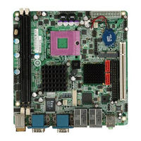
IEI Technology KINO-9652 User Manual (269 pages)
Brand:
IEI Technology
| Category:
Motherboard
| Size: 10 MB
Table of Contents
Packing List
6
Table of Contents
7
This Page Is Intentionally Left Blank
22
1 Introduction
23
Kino-9652 Overview
24
KINO-9652 Features
24
Figure 1-1: KINO-9652 Embedded SBC
24
Kino-9652 Board Overview
25
Figure 1-2: KINO-9652 Board Overview
25
KINO-9652 Connectors
26
Technical Specifications
27
Table 1-1: Technical Specifications
28
2 Detailed Specifications
29
Overview
30
Dimensions
30
Board Dimensions
30
Figure 2-1: KINO-9652 Dimensions (MM)
30
External Interface Panel Dimensions
31
Data Flow
31
Figure 2-2: External Interface Panel Dimensions (MM)
31
Compatible Processors
32
Figure 2-3: Data Flow Block Diagram
32
Intel ® Gm965 Graphics and Memory Controller Hub
33
Intel ® GM965 Overview
33
Table 2-1: Supported Intel® Core™2 Duo (Merom) Processors
33
Intel® GM965 Front Side Bus (FSB) Support
34
Intel ® GM965 Memory Support
34
Figure 2-4: Front Side Bus (FSB)
34
Figure 2-5: 240-Pin DDR2 DIMM Sockets
35
Intel ® GM965 Integrated Graphics
36
Intel GM965 Analog CRT Support
36
Intel GM965 LVDS Support
36
Intel
36
Figure 2-6: Integrated Graphics Interfaces
36
Intel ® GM965 Direct Management Interface (DMI)
37
Intel ® GM965 TV out Support
37
Intel ® Ich8Me I/O Controller Hub
38
Intel ® ICH8ME Overview
38
Figure 2-7: DMI Chip-To-Chip Connection
38
Intel ® ICH8ME HD Audio Controller
39
Figure 2-8: HD Audio Codec
39
Intel ® ICH8ME Ethernet Controller
40
Intel® 82566MM Gigabit LAN Connect Device
41
Intel ® ICH8ME IDE Interface
41
Figure 2-9: Intel® 82566MM Gigabit LAN Connect Device
41
Intel ® ICH8ME Low Pin Count (LPC) Interface
42
Intel ® ICH8ME PCI Interface
42
Table 2-2: Supported HDD Specifications
42
Intel ® ICH8ME Pcie X1 Bus
43
Intel ® ICH8ME Real Time Clock
43
Intel ® ICH8ME SATA Controller
43
Figure 2-10: PCI Slot
43
Intel ® ICH8ME Serial Peripheral Interface (SPI) BIOS
44
Intel ® ICH8ME USB Controller
44
Figure 2-11: SATA Drive Connectors
44
Pcie Bus Components
45
Pcie Bus Overview
45
Pcie Mini Card Expansion
45
Figure 2-12: Onboard USB Implementation
45
Pcie Bu Component
45
Intel® 82573L Pcie Gbe Controller
46
Figure 2-13: Pcie Mini Card Slot
46
Figure 2-14: Intel® 82573L Pcie Gbe Controller
46
Lpc Bus Components
47
LPC Bus Overview
47
TPM Module
47
Super I/O Chipset
48
Figure 2-15: TPM Connector
48
Figure 2-16: Ite IT8712F Super I/O
49
Super I/O 16C550 Uarts
50
Super I/O Enhanced Hardware Monitor
50
Super I/O Fan Speed Controller
50
Super I/O GPIO Ports
50
Super I/O Infrared
50
Super I/O LPC Interface
50
Super I/O Keyboard Controller
51
Fintek F81216DG LPC Serial Port Chipset
51
Environmental and Power Specifications
51
System Monitoring
51
Operating Temperature and Temperature Control
52
Power Consumption
53
Table 2-3: Power Consumption
53
3 Unpacking
55
Anti-Static Precautions
56
Unpacking
56
Unpacking Precautions
56
Unpacking Checklist
57
Package Contents
57
Optional Items
58
Table 3-1: Package List Contents
58
Table 3-2: Optional Items
59
4 Connectors and Jumpers
61
Peripheral Interface Connectors
62
KINO-9652 Layout
62
Figure 4-1: Connector and Jumper Locations
62
Peripheral Interface Connectors
63
Rear Panel Connectors
64
Table 4-1: Peripheral Interface Connectors
64
Table 4-2: Rear Panel Connectors
64
Internal Peripheral Connectors
65
Audio Connector
65
Figure 4-2: Audio Connector Location
65
Table 4-3: Audio Connector Pinouts
65
Audio CD in Connector
66
ATX Power Connector
66
Figure 4-3: Audio CD in Connector Pinouts (4-Pin)
66
Table 4-4: Audio CD in Connector Pinouts
66
Figure 4-4: ATX Power Connector Pinout Locations
67
Table 4-5: ATX Power Connector Pinouts
67
Compactflash® Socket (Optional)
68
Figure 4-5: CF Card Socket Location
69
Fan Connectors
70
Table 4-6: CF Card Socket Pinouts
70
Front Panel Connector
71
Figure 4-6: Fan Connector Locations
71
Table 4-7: Fan Connector Pinouts
71
Figure 4-7: Front Panel Connector Location
72
Table 4-8: Front Panel Connector Pinouts
72
Digital Input/Output Connector
73
Figure 4-8: GPIO Connector Location
73
Table 4-9: GPIO Connector Pinouts
73
IDE Connector
74
Figure 4-9: IDE Device Connector Location
74
Infrared Interface Connector
75
Table 4-10: IDE Connector Pinouts
75
LCD Backlight Connector
76
Figure 4-10: Infrared Connector Pinout Locations
76
Table 4-11: Infrared Connector Pinouts
76
LVDS LCD Connector
77
Figure 4-11: LCD Backlight Connector Location
77
Table 4-12: LCD Backlight Connector Pinouts
77
Figure 4-12: LVDS LCD Connector Location
78
SATA Drive Connectors
79
Figure 4-13: SATA Drive Connector Locations
79
Table 4-13: LVDS LCD Connector Pinouts
79
Serial Port Connector
80
Figure 4-14: 14-Pin Serial Port Connector Locations
80
Table 4-14: SATA Drive Connector Pinouts
80
Trusted Platform Module (TPM) Connector
81
Table 4-15: COM1 Pinouts
81
TV out Connector
82
Figure 4-15: TPM Connector Pinout Locations
82
Table 4-16: TPM Connector Pinouts
82
Figure 4-16: TV Connector Pinout Locations
83
Table 4-17: TV Port Connector Pinouts
83
Internal USB Connectors
84
Figure 4-17: Internal USB Connector Locations
84
Table 4-18: USB3 and USB4 Pinouts
84
External Interface Connectors
85
Audio Connectors
85
Figure 4-18: KINO-9652 External Interface Connectors
85
CRT Connector
86
Figure 4-19: Audio Connectors
86
Figure 4-20: VGA Connector
86
Ethernet Connectors
87
Figure 4-21: RJ-45 Ethernet Connector
87
Table 4-19: VGA Connector Pinouts
87
Table 4-20: LAN1 and LAN2 Pinouts
87
Keyboard/Mouse Connector
88
Figure 4-22: PS/2 Pinouts
88
Table 4-21: RJ-45 Ethernet Connector Leds
88
Serial Port Connectors
89
Figure 4-23: External Serial Port Connector
89
Table 4-22: PS/2 Connector Pinouts
89
USB Connector
90
Table 4-23: External Serial Port Pinouts
90
Table 4-24: External USB Connector Pinouts
90
5 Installation
91
Anti-Static Precautions
92
Installation Considerations
93
Installation Notices
93
Installation Checklist
94
Cpu, Cpu Cooling Kit and DIMM Installation
95
Socket P CPU Installation
95
Figure 5-1: Make Sure the CPU Socket Retention Screw Is Unlocked
96
Figure 5-2: Lock the CPU Socket Retention Screw
97
Cooling Kit CF-479B-RS Installation
98
Figure 5-3: IEI CF-479B-RS Cooling Kit
98
Figure 5-4: Cooling Kit Support Bracket
99
Figure 5-5: Connect the Cooling Fan Cable
99
DIMM Installation
100
Figure 5-6: Installing a DIMM
101
Jumper Settings
102
Clear CMOS Jumper
102
Figure 5-7: Jumper Locations
102
Table 5-1: Jumpers
102
Table 5-2: Clear CMOS Jumper Settings
103
COM 4 Function Select Jumper
104
Figure 5-8: Clear CMOS Jumper
104
Table 5-3: COM 4 Function Select Jumper Settings
104
COM Port Pin 9 Setting Jumpers
105
Figure 5-9: COM 4 Function Select Jumper Location
105
Figure 5-10: COM Port Pin 9 Setting Jumper Locations
106
Table 5-4: COM 1/2 Pin 9 Setting Jumper Settings
106
Table 5-5: COM 3/4 Pin 9 Setting Jumper Settings
106
LVDS Voltage Selection
107
Table 5-6: LVDS Voltage Selection Jumper Settings
107
LVDS Panel Resolution Selection
108
Figure 5-11: LVDS Voltage Selection Jumper Pinout Locations
108
Chassis Installation
109
Airflow
109
Figure 5-12: LVDS Resolution Selection Jumper Pinout Locations
109
Table 5-7: LVDS Resolution Selection Jumper Settings
109
Motherboard Installation
110
Internal Peripheral Device Connections
110
Peripheral Device Cables
110
Table 5-8: IEI Provided Cables
110
IDE Cable Connection
111
Figure 5-13: IDE Cable Connection
111
Dual RS-232 Cable Connection
112
SATA Drive Connection
112
Figure 5-14: Dual RS-232 Cable Installation
112
Figure 5-15: SATA Drive Cable Connection
113
USB Cable (Dual Port) with Slot Bracket
114
Figure 5-16: SATA Power Drive Connection
114
External Peripheral Interface Connection
115
Figure 5-17: Dual USB Cable Connection
115
Audio Connection
116
Ethernet and USB Connection
116
Figure 5-18: Audio Connectors
116
Figure 5-19: RJ-45 Ethernet Connector
117
VGA Monitor Connection
117
Figure 5-20: VGA Connector
118
Serial Device Connection
118
Figure 5-21: Serial Device Connector
119
PS/2 Keyboard/Mouse Connection
119
Figure 5-22: PS/2 Keyboard/Mouse Connector
120
6 Ami Bios
121
Introduction
122
Starting Setup
122
Using Setup
122
Getting Help
123
Unable to Reboot after Configuration Changes
123
BIOS Menu Bar
123
Table 6-1: BIOS Navigation Keys
123
Main
124
Advanced
125
CPU Configuration
126
IDE Configuration
127
Menu 4: IDE Configuration
128
IDE Master, IDE Slave
129
Menu 5: IDE Master and IDE Slave Configuration
130
Super IO Configuration
134
Hardware Health Configuration
137
Intel AMT Configuration
138
Intel Robson Configuration
139
Remote Access Configuration
140
Menu 10: Remote Access Configuration [Advanced]
141
Trusted Computing
143
USB Configuration
144
Menu 12: USB Configuration
145
USB Mass Storage Device Configuration
147
Power Configuration
149
ACPI Configuration
150
APM Configuration
151
Pci/Pnp
153
Menu 17: Pci/Pnp Configuration
154
Boot
156
Boot Settings Configuration
156
Menu 19: Boot Settings Configuration
157
Boot Device Priority
159
Removable Drives
159
Security
161
Chipset
162
Northbridge Configuration
162
Menu 23:Northbridge Chipset Configuration
163
Video Function Configuration
164
Southbridge Configuration
165
Menu 24:Southbridge Chipset Configuration
166
ME Subsystem Configuration
167
Exit
169
7 Software Drivers
171
Available Software Drivers
172
Driver CD Auto-Run
172
Figure 7-1: Introduction Screen
173
Figure 7-2: Available Drivers
173
Intel® Chipset Driver
174
Figure 7-3: Intel® Chipset Driver Directory
174
Figure 7-4: Intel® Chipset Driver Setup Icon
175
Figure 7-5: Intel® Package Manager
176
Figure 7-6: Intel® Setup Welcome Screen
176
Figure 7-7: Intel® Chipset Driver License Agreement
177
Figure 7-8: Readme File
177
Intel® Graphics Media Accelerator Driver
178
Figure 7-9: Intel® Chipset Driver Complete Installation Screen
178
Figure 7-10: Select the Operating System
179
Figure 7-11: Intel® Driver Directory
179
Figure 7-12: Intel® VGA Driver Setup Icon
180
Figure 7-13: GMA Driver Readme File
181
Figure 7-14: GMA Driver File Extraction
181
Figure 7-15: GMA Driver Installation Welcome Screen
182
Figure 7-16: GMA Driver License Agreement
182
Intel® 82566 Gigabit LAN Connect Device Driver
183
Figure 7-17: GMA Driver Installing Notice
183
Figure 7-18: GMA Driver Installation Complete
183
Figure 7-19: Intel® 82566 Driver Directory Icon
184
Figure 7-20: Intel® 82566 Operating System
185
Figure 7-21: Select Operating System Type
186
Figure 7-22: Driver Directory
186
Figure 7-23: Intel® 82566 Device Driver Startup Icon
187
Figure 7-24: Intel® 82566 Welcome Screen
188
Figure 7-25: Intel® 82566 Driver License Agreement
188
Figure 7-26: Intel® 82566 Driver Setup Options
189
Figure 7-27: Intel® 82566 Driver Installation Ready Window
189
Intel® 82573 PCI Express Gigabit Ethernet Controller Driver
190
Figure 7-28: Intel® 82566 Driver Installation Progress
190
Figure 7-29: Intel® 82573 Driver Directory Icon
191
Figure 7-30: Intel® 82573 Operating System
192
Figure 7-31: Select Operating System Type
193
Figure 7-32: Driver Directory
193
Figure 7-33: Intel® 82573 Driver Startup Icon
194
Figure 7-34: Intel® 82573 License Agreement
195
Figure 7-35: Intel® 82573 File Location Select
195
Figure 7-36: Intel® 82573 Installation Files Extraction
196
Figure 7-37: Intel® PRO Network Connections Window
196
Figure 7-38: Intel® PRO Network Connections Welcome
197
Figure 7-39: License Agreement
197
Figure 7-40: Setup Type
198
Figure 7-41: Intel® 82573 Driver Installation Progress
198
Realtek Hd Audio Driver (Alc883) Installation
199
BIOS Setup
199
Driver Installation
199
Figure 7-42: Select the Audio CODEC
200
Figure 7-43: Select the os
201
Figure 7-44: Select the os Version
201
Figure 7-45: Locate the Setup Program Icon
202
Figure 7-46: the Installshield Wizard Starts
202
Figure 7-47: Preparing Setup Screen
203
Figure 7-48: Installshield Wizard Welcome Screen
203
Figure 7-49: Audio Driver Software Configuration
204
Figure 7-50: Installation Wizard Updates the System
204
Intel ® Matrix Storage Manager Driver Installation
205
Figure 7-51: Restart the Computer
205
Figure 7-52: SATA RAID Driver Installation Program
206
Figure 7-53: SATA RAID Setup Program Icon
207
Figure 7-54: Installshield Wizard Setup Screen
207
Figure 7-55: Matrix Storage Manager Setup Screen
208
Figure 7-56: Matrix Storage Manager Welcome Screen
208
Figure 7-57: Matrix Storage Manager Warning Screen
209
Figure 7-58: Matrix Storage Manager License Agreement
209
Figure 7-59: Matrix Storage Manager Readme File
210
Figure 7-60: Matrix Storage Manager Setup Complete
210
Intel® Active Management Technology Driver Installation
211
Figure 7-61: IAMT Driver Directory
211
Figure 7-62: IAMT Driver Installation Icon
212
Figure 7-63: IAMT Welcome Screen
212
Figure 7-64: IAMT License Agreement
213
Figure 7-65: IAMT Readme File
213
Figure 7-66: IAMT Setup Operations
214
Figure 7-67: Completed Installation
214
Figure 7-68: IAMT Driver Directory
215
Figure 7-69: HECI Driver Installation Icon
215
8 Intel Amt Configuration
217
Intel ® Amt Setup Procedure
218
Figure 8-1: Intel® Active Management Technology Status Dialog
218
Intel ® Management Engine Bios Extension
219
Figure 8-2: Intel® Current ME Password
219
Figure 8-3: Change Intel® ME Password
220
Figure 8-4: Verify New Password
220
Figure 8-5: Intel® AMT Configuration
220
Figure 8-6: Provision Model
221
Figure 8-7: Intel® AMT 2.0 Mode
221
Figure 8-8: Enterprise
222
Figure 8-9: Enable Network Interface
222
Figure 8-10: Exit
223
Using the Intel AMT Web Interface
224
Figure 8-11: Intel® AMT Web Address
224
Figure 8-12: Intel® AMT Web Login Dialog
225
Figure 8-13: Intel® AMT Web Interface
226
Abios Configuration Options
227
Bios Configuration Options
227
O Ptions
228
Bterminology
232
Cdio Interface
238
Dio Interface Introduction
239
Dio Connector Pinouts
239
Assembly Language Samples
240
Enable the DIO Input Function
240
Enable the DIO Output Function
240
Dwatchdog Timer
242
Eaddress Mapping
246
Io Address Map
247
St Mb Memory Address Map
247
Addres Map
247
Irq Mapping Table
248
Dma Channel Assignments
248
Fcompatibility
250
Compatible Processors
251
Compatible Memory Modules
251
Hazardous Materials Disclosure
254
Hazardous Material Disclosure Table for IPB Products Certified as Rohs Compliant under 2002/95/EC Without Mercury
255
Hexternal Ac'97 Audio Codec
258
Introduction
259
Accessing the AC'97 CODEC
259
Driver Installation
259
H.1 I Ntroduction
259
Sound Effect Configuration
260
Accessing the Sound Effects Manager
260
Sound Effect Manager Configuration Options
261
Iindex
264
Advertisement
Advertisement
Related Products
IEI Technology KINO-9653
IEI Technology Kino-9654G4
IEI Technology KINO-9453
IEI Technology KINO-945GSE3
IEI Technology KINO-9152G4
IEI Technology KINO-945GSE2
IEI Technology KINO-9454
IEI Technology KINO-9451
IEI Technology KINO-9452
IEI Technology KINO-9455
IEI Technology Categories
Motherboard
Touch Panel
Computer Hardware
Single board computers
Desktop
More IEI Technology Manuals
Login
Sign In
OR
Sign in with Facebook
Sign in with Google
Upload manual
Upload from disk
Upload from URL