Sign In
Upload
Manuals
Brands
IEI Technology Manuals
Motherboard
IMB-ADL-Q670
IEI Technology IMB-ADL-Q670 Manuals
Manuals and User Guides for IEI Technology IMB-ADL-Q670. We have
2
IEI Technology IMB-ADL-Q670 manuals available for free PDF download: User Manual, Quick Installation Manual
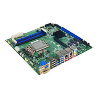
IEI Technology IMB-ADL-Q670 User Manual (161 pages)
MicroATX motherboard supports LGA1700 12th/13th Generation Intel Core i9/i7/i5/i3, Pentium and Celeron processor, triple independent display, dual 2.5GbE LAN, M.2, DDR4, USB 3.2, SATA 6Gb/s, HD Audio and RoHS
Brand:
IEI Technology
| Category:
Motherboard
| Size: 13 MB
Table of Contents
Table of Contents
5
Introduction
15
Ntroduction
16
Figure 1-1: IMB-ADL-Q670
16
Features
17
Connectors
18
Figure 1-2: Connectors
18
Dimensions
19
Figure 1-3: IMB-ADL-Q670 Dimensions (MM)
19
Data Flow
20
Figure 1-4: Data Flow Diagram
20
Technical Specifications
21
Table 1-1: IMB-ADL-Q670 Specifications
22
Packing List
23
Anti-Static Precautions
24
Unpacking Precautions
24
Packing List
25
Table 2-1: Packing List
25
Optional Items
26
Table 2-2: Optional Items
26
Connectors
27
Peripheral Interface Connectors
28
IMB-ADL-Q670 Layout
28
Figure 3-1: Peripheral Interface Connectors
28
External Interface Panel Connectors
30
Table 3-1: Peripheral Interface Connectors
30
Table 3-2: Rear Panel Connectors
30
Internal Peripheral Connectors
31
CPU 12V Power Connector
31
Figure 3-2: CPU 12V Power Connector Location
31
ATX Power Connector
32
Figure 3-3: ATX Power Connector Location
32
Table 3-3: CPU 12V Power Connector Pinouts
32
Battery Connector
33
Table 3-4: ATX Power Connector Pinouts
33
Chassis Intrusion Connector
34
Figure 3-4: Battery Connector Location
34
Table 3-5: Battery Connector Pinouts
34
Figure 3-5: Chassis Intrusion Connector Location
35
Table 3-6: Chassis Intrusion Connector Pinouts
35
AT/ATX Power Mode Setting
36
Figure 3-6: AT/ATX Power Mode Switch Locations
36
Table 3-7: AT/ATX Power Mode Switch Settings
36
Digital I/O Connector
37
Figure 3-7: Digital I/O Connector Location
37
Table 3-8: Digital I/O Connector Pinouts
37
EC Debug Connector
38
Figure 3-8: EC Debug Connector Location
38
Table 3-9: EC Debug Connector Pinouts
38
Clear CMOS Button
39
Figure 3-9: Clear CMOS Jumper Location
39
Table 3-10: Clear CMOS Jumper Pinouts
39
Fan Connector (CPU)
40
Figure 3-10: CPU Fan Connector Location
40
Table 3-11: CPU Fan Connector Pinouts
40
Fan Connectors (System)
41
Figure 3-11: System Fan Connector Locations
41
Table 3-12: System Fan Connector Pinouts
41
Audio Connector
42
Figure 3-12: Audio Connector Location
42
Table 3-13: Audio Connector Pinouts
42
Front Panel Connector
43
Figure 3-13: Front Panel Connector Location
43
Table 3-14: Front Panel Connector Pinouts
43
I 2 C Connector
44
Figure 3-14: I 2 C Connector Location
44
Table 3-15: I² C Connector Pinouts
44
Smbus Connector
45
Figure 3-15: Smbus Connector Location
45
Table 3-16: Smbus Connector Pinouts
45
LAN Link LED Connector
46
Figure 3-16: LAN LED Connector Locations
46
Table 3-17: LAN1 LED Connector (JLAN_LED1) Pinouts
46
Table 3-18: LAN2 LED Connector (JLAN_LED 2) Pinouts
46
M-Key Slot
47
Figure 3-17: M.2 M-Key Slot Location
47
Table 3-19: M.2 M-Key Connector Pinouts
48
Pcie X1 Slots
49
Figure 3-18: Pcie X1 Slot Locations
49
Pcie X4 Slots
50
Figure 3-19: Pcie X4 Slot Locations
50
Pcie X16 Slots
51
Figure 3-20: Pcie X16 Slot Locations
51
Onboard Power Button
52
Figure 3-21: Power Button Location
52
DDR4 DIMM Sockets
53
Figure 3-22: DDR4 DIMM Sockets Location
53
SATA 6Gb/S Connectors
54
Figure 3-23: SATA 6Gb/S Connector Locations
54
Table 3-20: SATA 6Gb/S Connector Pinouts
54
Serial Port Connectors
55
Figure 3-24: RS-232 Connector Location
55
Table 3-21: RS-232 Connector Pinouts
56
Serial Port Connectors
57
Figure 3-25: RS-232 Connector Location
57
Table 3-22: RS-232 Connector Pinouts
58
RS-232/422/485 Serial Port Connectors
59
Figure 3-26: RS-232/422/485 Connector Location
59
Table 3-23: RS-232/422/485 Connector Pinouts
59
Flash SPI ROM Connector
60
Figure 3-27: Flash SPI ROM Connector Location
60
Table 3-24: Flash SPI ROM Connector Pinouts
60
RAA229132 FW Flash Connector
61
Figure 3-28: RAA229132 FW Flash Connector Location
61
Table 3-25: RAA229132 FW Flash Connector Pinouts
61
MP2940C FW Flash Connector
62
Figure 3-29: MP2940C FW Flash Connector Location
62
Table 3-26: MP2940C FW Flash Connector Pinouts
62
External Peripheral Interface Connector Panel
63
External USB 2.0 Connector
63
Figure 3-30: External Peripheral Interface Connector
63
Figure 3-31: USB 2.0 Connector
63
External USB 3.2 Gen 1 Connector
64
Figure 3-32: USB 3.2 Gen 1 Connector
64
Table 3-27: USB 2.0 Port Pinouts
64
Table 3-28: USB 3.2 Gen 1 Port Pinouts
64
External 2.5Gbe RJ-45 and Dual USB 3.2 Gen 2 Combo Connector
65
Figure 3-33: USB 3.2 and RJ45 Connector
65
Table 3-29: USB 3.2 Port Pinouts
65
External VGA and DVI-I Combo Connector
66
Figure 3-34: VGA and DVI-I Connector
66
Table 3-30: Dual RJ45 Pinouts
66
Table 3-31: External VGA Connector Pinouts
67
Table 3-32: External DVI-I Connector Pinouts
67
Installation
68
Anti-Static Precautions
69
Internal Peripheral Device Connections
69
SATA Drive Connection
69
Figure 4-1: SATA Drive Cable Connection
70
Figure 4-2: SATA Power Drive Connection
71
Installation Considerations
72
Socket Lga1700 Cpu Installation
73
Figure 4-3: Disengage the CPU Socket Load Lever
74
Figure 4-4: Remove Protective Cover
75
Figure 4-5: Insert the Socket LGA1700 CPU
76
Socket Lga1700 Cooling Kit Installation
77
Figure 4-6: Close the Socket LGA1700
77
Figure 4-7: Cooling Kit Support Bracket
78
DIMM Installation
79
Figure 4-8: DIMM Installation
79
Module Installation
80
Figure 4-9: Inserting the M.2 Module into the Slot at an Angle
80
Figure 4-10: Securing the M.2 Module
81
Figure 4-11: Press the Retainer
81
Figure 4-12: Aligning the M.2 Module with the Retainer
82
Figure 4-13: Securing the M.2 Module
82
Software Installation
83
Driver Download
83
Figure 4-14: IEI Resource Download Center
83
Bios
85
Introduction
86
Starting Setup
86
Figure 5-1: BIOS Starting Menu
86
Using Setup
87
Keyboard Navigation
87
Table 5-1: BIOS Navigation Keys
87
Touch Navigation
88
Table 5-2: BIOS On-Screen Navigation Keys
88
Getting Help
89
Unable to Reboot after Configuration Changes
89
BIOS Menu Bar
89
Main
90
Advanced
93
CPU Configuration
95
Trusted Computing
100
BIOS Menu 10: PCH-FW Configuration
100
RTC Wake Settings
101
F81966 Super IO Configuration
103
BIOS Menu 13: F81966 Super IO Configuration
103
Serial Port 1 Configuration
104
BIOS Menu 14: Serial Port 1 Configuration Menu
104
Serial Port 2 Configuration
105
BIOS Menu 15: Serial Port 2 Configuration Menu
105
Serial Port 3 Configuration
106
BIOS Menu 16: Serial Port 3 Configuration Menu
106
Serial Port 4 Configuration
107
BIOS Menu 17: Serial Port 4 Configuration Menu
107
Serial Port 5 Configuration
108
BIOS Menu 18: Serial Port 5 Configuration Menu
108
Serial Port 6 Configuration
109
BIOS Menu 19: Serial Port 6 Configuration Menu
109
F81216SEC Super IO Configuration
110
BIOS Menu 20: F81216SEC Super IO Configuration
110
Serial Port 7 Configuration
111
BIOS Menu 21: Serial Port 7 Configuration Menu
111
Serial Port 8 Configuration
112
BIOS Menu 22: Serial Port 8 Configuration Menu
112
Serial Port 9 Configuration
113
BIOS Menu 23: Serial Port 9 Configuration Menu
113
Serial Port 10 Configuration
114
BIOS Menu 24: Serial Port 10 Configuration Menu
114
EC KB9068 H/W Monitor
115
Smart Fan Mode Configuration
117
BIOS Menu 27: Smart Fan Mode Configuration
117
Serial Port Console Redirection
119
Console Redirection Settings
121
BIOS Menu 32: COM Console Redirection Settings
122
Nvme Configuration
124
BIOS Menu 33: Nvme Configuration
124
Chipset
125
BIOS Menu 34: Chipset
125
System Agent (SA) Configuration
126
BIOS Menu 35: System Agent (SA) Configuration
126
Memory Configuration
127
BIOS Menu 36: Memory Configuration
127
Graphics Configuration
128
BIOS Menu 37: Graphics Configuration
128
BIOS Menu 38: LCD Control
130
VMD Configuration
131
BIOS Menu 39: VMD Configuration
131
PEG Port Configuration
132
BIOS Menu 40: PEG Port Configuration
132
PCH-IO Configuration
133
PCI Express Configuration
135
BIOS Menu 43: PCI Express Configuration
135
Pcie Root Port Setting
136
BIOS Menu 44: Pcie Slot Configuration Submenu
136
SATA Configuration
138
BIOS Menu 45: SATA Configuration
138
HD Audio Configuration
139
BIOS Menu 46: HD Audio Configuration
139
Security
140
Boot
142
Boot Configuration
142
BIOS Menu 49: Boot
142
Boot Option Priorities
143
Save & Exit
144
BIOS Menu 50: Save & Exit
144
A Regulatory Compliance
146
B Product Disposal
148
CBIOS Options
150
D Watchdog Timer
154
E Error Beep Code
157
Pei Beep Codes
158
Dxe Beep Codes
158
F Hazardous Materials Disclosure
159
Rohs II Directive (2015/863/EU)
160
China Rohs
161
Advertisement
IEI Technology IMB-ADL-Q670 Quick Installation Manual (16 pages)
micro-ATX Motherboard
Brand:
IEI Technology
| Category:
Motherboard
| Size: 0 MB
Advertisement
Related Products
IEI Technology IMB-ADL-H610
IEI Technology IMB-ADL-Q670-R10
IEI Technology IMBA-9454G
IEI Technology IMBA-C604EN
IEI Technology IMBA-BDE-1518
IEI Technology IMBA-Q370-R20
IEI Technology IMBA-Q370-R10
IEI Technology IMBA-R680
IEI Technology IMBA-H810-R10
IEI Technology IMBA-BDE-D1548-R10
IEI Technology Categories
Motherboard
Touch Panel
Computer Hardware
Single board computers
Desktop
More IEI Technology Manuals
Login
Sign In
OR
Sign in with Facebook
Sign in with Google
Upload manual
Upload from disk
Upload from URL