Sign In
Upload
Manuals
Brands
IEI Technology Manuals
Touch Panel
IOVU-xxF-AD
IEI Technology IOVU-xxF-AD Manuals
Manuals and User Guides for IEI Technology IOVU-xxF-AD. We have
1
IEI Technology IOVU-xxF-AD manual available for free PDF download: User Manual
IEI Technology IOVU-xxF-AD User Manual (89 pages)
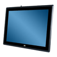
12'/15'/17' RISC-Based Panel PC with Touchscreen, Freescale i.MX6 Cortex-A9 Quad-Core CPU, CAN 2.0, Android 4.2.2 OS, Wi-Fi, Bluetooth, PoE, RoHS Compliant
Brand:
IEI Technology
| Category:
Touch Panel
| Size: 6 MB
Table of Contents
Table of Contents
5
1 Introduction
11
Figure 1-1: IOVU-Xxf-AD Panel PC
12
Figure 1-3: Rear Panel
14
Figure 1-4: IO Interfaces
15
System Specifications
16
Dimensions
17
Table 1-2: Technical Specifications
17
D Imensions 1.8.1 Iovu-12F-Ad
18
Dimensions
18
Figure 1-5: IOVU-12F-AD Dimensions (Unit: MM)
18
Iovu-12F-Ad
18
Figure 1-6: IOVU-15F-AD Dimensions (Unit: MM)
19
Iovu-15F-Ad
19
Iovu-17F-Ad
20
Figure 1-2: Front Panel
14
I/O Interfaces
15
Model Variations
12
Overview
12
Table 1-1: Model Variations
12
Features
13
Front Panel
14
Rear Panel
14
Figure 1-7: IOVU-17F-AD Dimensions (Unit: MM)
20
2 Unpacking
21
Packing List
22
Optional Items
23
Table 2-1: Packing List
23
Table 2-2: Optional Items
25
3 Installation
26
Anti-Static Precautions
27
Installation Precautions
27
Figure 3-1: Retention Screws on the Rear Cover
28
Figure 3-2: Microsd Card Installation
28
Microsd Card Installation
28
Mounting the System
29
Wall Mounting
29
Figure 3-3: Wall-Mounting Bracket
30
Figure 3-5: Secure the IOVU-Xxf-AD
31
Figure 3-4: Chassis Support Screws
31
Figure 3-6: IOVU-12F-AD Panel Cutout Dimensions
32
Figure 3-7: IOVU-15F-AD Panel Cutout Dimensions
32
Figure 3-9: Mounting Bracket Installation
33
Figure 3-8: IOVU-17F-AD Panel Cutout Dimensions
33
Arm Mounting
34
Figure 3-10: Tightening the Mounting Clamp Screws
34
Figure 3-11: Arm Mounting Retention Screw Holes
35
Figure 3-12: Arm Mounting
35
Figure 3-13: Stand Mounting
36
Figure 3-14: 10-Pin I/O Connector Pinouts Location
37
Table 3-1: 10-Pin I/O Connector Pinouts
37
DC Power Input Interfaces
38
Figure 3-15: 12 V ~ 36 V DC Power Input Connector Locations
38
Figure 3-16: DC-In Power Terminal Block
38
Table 3-2: DC-In Power Terminal Block Pinouts
38
10/100/1000 Mbps Poe Connector
39
Figure 3-17: RJ-45 Connector
39
Table 3-3: RJ-45 Connector Pinouts
39
RS-232 Serial Interface Pinouts (COM 1)
40
Serial Interfaces
40
Table 3-4: RJ-45 Connector Leds
40
Table 3-5: RS-232 Serial Port Pinouts
40
RS-232/422/485 Serial Interface Pinouts (COM 2)
41
System Maintenance
41
Table 3-6: RS-232/422/485 Serial Port Pinouts
41
Table 3-7: USB 2.0 Host Connector Pinouts
41
USB 2.0 Host Connectors
41
Stand Mounting
36
External I/O Connectors
37
10-Pin I/O Connector
37
Panel Mounting
32
4 Using the Iovu-Xxf-Ad
42
Figure 4-1: Power Switch
43
Figure 4-4: Multiple Home Screens
45
Figure 4-5: Launcher Button
46
Figure 4-6: Launcher Page
46
Figure 4-7: Favorites Tray
47
Arranging the Home Screen
48
Figure 4-8: Move and Trash Item on Home Screen
48
Figure 4-9: Navigation Buttons
49
Navigation Buttons
49
Table 4-1: Navigation Buttons
49
Figure 4-10: Status Bar
50
Figure 4-11: Status Bar - Setting Shortcut
50
Status Bar
50
Figure 4-12: Status Bar - Notification
51
Figure 4-13: Wireless and Networks Settings
52
Settings
52
Wireless & Networks
52
Figure 4-14: more Settings Menu
53
More Settings
53
Figure 4-15: Sound Menu
54
Sound
54
Display
55
Figure 4-16: Display Menu
55
Figure 4-17: Storage Menu
56
Storage
56
Apps
57
Figure 4-18: Apps Menu
57
Figure 4-19: Users Menu
57
Users
57
Figure 4-20: Location Access Menu
58
Location Access
58
Figure 4-21: Security Menu
59
Security
59
Figure 4-22: Language & Input Menu
60
Language & Input
60
Add Account
61
Backup & Reset
61
Figure 4-23: Backup & Reset Menu
61
Figure 4-24: Add Account Menu
61
Date & Time
62
Figure 4-25: Date & Time Menu
62
Accessibility
63
Figure 4-26: Accessibility Menu
63
About Tablet
64
Figure 4-27: about Tablet Menu
64
Figure 4-28: es File Explorer Screen
65
File Management
65
Favorites Tray
47
Power-On/Off Procedure
43
Installation Checklist
43
Power-On Procedure
43
Figure 4-2: Power-Off Menu
44
Figure 4-3: Power-Off Confirmation Screen
44
Power-Off Procedure
44
Home Screen
45
Switching between Home Screens
45
Adding Shortcuts
45
Figure 4-29: Possible Storage Devices
66
5 Interface Connectors
67
Figure 5-1: Main Board Layout Diagram
68
Table 5-1: Peripheral Interface Connectors
69
12"/15" LCD Connector (12_15_CN1)
70
17" LCD Connector (17_21_24_CN)
70
Table 5-2: 12"/15" LCD Connector (12_15_CN1) Pinouts
70
Backlight Inverter Connector (CN6)
71
Install os Switch (SW3)
71
JATG Interface for Wi-Fi & BT Module (CN15)
71
Table 5-3: 17" LCD Connector (17_21_24_CN) Pinouts
71
Peripheral Interface Connectors
68
Internal Peripheral Connectors
69
Table 5-6: JATG Interface for Wi-Fi & BT Module (CN15) Pinouts
71
Table 5-5: Install os Switch (SW3) Pinouts
71
Table 5-4: Backlight Inverter Connector (CN6) Pinouts
71
Left Speaker Connector (CN11)
72
Microphone Connector (MIC1)
72
Power Button Connector (CN18)
72
Power LED Connector (JP1)
72
Right Speaker Connector (CN13)
72
Table 5-10: Power LED Connector (JP1) Pinouts
72
Table 5-11: Right Speaker Connector (CN13) Pinouts
72
Table 5-12: Touchscreen Connector (J1) Pinouts
73
Table 5-13: UART COM Port (CN20) Pinouts
73
Table 5-14: UART Connector (Debug COM Port) (CN14) Pinouts
73
Table 5-15: USB Client Connector (USB2) Pinouts
74
Table 5-16: USB Host Connector (J3) Pinouts
74
USB Client Connector (USB2)
74
USB Host Connector (J3)
74
Preconfigured Jumper/Switch Settings
75
Panel Backlight Setting Jumper (JP2)
75
Panel Selection Switch (SW4)
75
Table 5-9: Power Button Connector (CN18) Pinouts
72
Table 5-8: Microphone Connector (MIC1) Pinouts
72
Table 5-7: Left Speaker Connector (CN11) Pinouts
72
Touchscreen Connector (J1)
73
UART COM Port (CN20)
73
UART Connector (Debug COM Port) (CN14)
73
Table 5-17: Preconfigured Jumpers/Switches
75
Table 5-18: Panel Backlight Setting Jumper (JP2) Settings
75
Table 5-19: Panel Selection Switch (JP2) Settings
75
A Regulatory Compliance
76
B Safety Precautions
81
Safety Precautions
82
General Safety Precautions
82
Anti-Static Precautions
83
Product Disposal
84
Maintenance and Cleaning Precautions
84
Maintenance and Cleaning
84
Cleaning Tools
85
C Hazardous Materials Disclosure
86
Hazardous Materials Disclosure Table for IPB Products Certified as Rohs Compliant under 2002/95/EC Without Mercury
87
C.1 H Azardous M Aterials D Isclosure T Able for Ipb P Roducts C Ertified as R O Hs C Ompliant U Nder 2002/95/Ec W Ithout M Ercury
87
Advertisement
Advertisement
Related Products
IEI Technology IOVU-570M
IEI Technology IOVU-572M
IEI Technology IOVU-571N
IEI Technology IOVU-752S
IEI Technology IOVU-751R-CE5/UX-R10
IEI Technology IOVU-207AR-RK39
IEI Technology IOVU-210AR-RK39
IEI Technology IOVU-210AD-RK39
IEI Technology IOBA-10F-AD
IEI Technology IASO-W08PLED-N6210
IEI Technology Categories
Motherboard
Touch Panel
Computer Hardware
Single board computers
Desktop
More IEI Technology Manuals
Login
Sign In
OR
Sign in with Facebook
Sign in with Google
Upload manual
Upload from disk
Upload from URL