Sign In
Upload
Manuals
Brands
IEI Technology Manuals
Touch Panel
IKARPC-W10A
IEI Technology IKARPC-W10A Manuals
Manuals and User Guides for IEI Technology IKARPC-W10A. We have
1
IEI Technology IKARPC-W10A manual available for free PDF download: User Manual
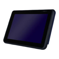
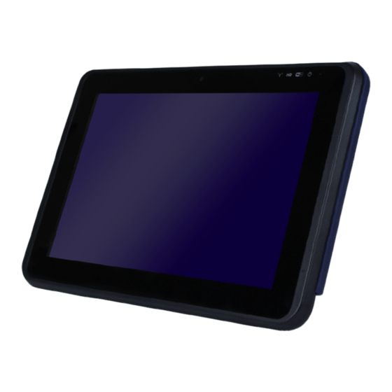
IEI Technology IKARPC-W10A User Manual (118 pages)
10.1” In-Vehicle Panel PC with Touchscreen, Intel Atom Processor E3826, OBD-II, GPS, USB 2.0/3.0, HDMI, RS-232/422/485, RoHS Compliant, IP 64 Front Panel
Brand:
IEI Technology
| Category:
Touch Panel
| Size: 3 MB
Table of Contents
Table of Contents
5
Introduction
13
Overview
14
Features
14
Figure 1-1: IKARPC-W10A-BT Panel PC
14
Front Panel
15
Figure 1-2: Front View
15
LED Indicators
16
Figure 1-3: LED Indicators
16
Table 1-1: LED Indicators
16
Rear Panel
17
Bottom Panel
17
Figure 1-4: Rear Panel
17
Right Side Panel
18
Figure 1-5: Bottom View
18
Figure 1-6: Right Side Panel
18
Top Panel
19
System Specifications
19
Figure 1-7: Top Panel
19
Table 1-2: Technical Specifications
21
Dimensions
22
Figure 1-8: Dimensions (Unit: MM)
22
Unpacking
23
Packing List
24
Optional Items
25
Table 2-1: Packing List
25
Table 2-2: Optional Items
27
Installation
28
Anti-Static Precautions
29
Installation Precautions
29
Sd Card Installation
30
Figure 3-1: I/O Cover of the Side Panel
30
Figure 3-2: Install SD Card
30
Sim Card Installation
31
Figure 3-3: SIM Card Slot Access Panel Retention Screws
31
Hdd/Ssd Installation
32
Figure 3-4: Install SIM Card
32
Figure 3-5: Back Cover Retention Screws
33
Figure 3-6: HDD Holder Bracket Retention Screw
34
Figure 3-7: HDD Installation
35
Figure 3-8: Secure HDD with Holder Bracket
35
Mounting the System
36
Figure 3-9: VESA Mount Retention Screw Holes
36
External I/O Connectors
37
COM Port Connection
37
Figure 3-10: RS-232 Connector (COM1, COM2)
37
Table 3-1: RS-232 Connector Pinouts
37
GPIO and RS-422/485 Connection
38
Figure 3-11: GPIO and RS-422/485 Connector
38
Table 3-2: GPIO and RS-422/485 Connector Pinouts
38
OBD-II Connection
39
Figure 3-12: OBD-II Connector
39
Table 3-3: OBD-II Connector Pinouts
39
Figure 3-13: OBD-II Cable and J1939/FMS Cable
40
Figure 3-14: OBD-II Connector Pinouts
40
Figure 3-15: J1939/FMS Connector Pinouts
40
Power Input Connection
41
Figure 3-16: Power Input Connector
41
Figure 3-17: ACC Power Cable
41
Table 3-4: Power Input Connector Pinouts
41
Power-On Procedure
42
Figure 3-18: Optional Cigarette Lighter Cable
42
Power State
43
System Maintenance
43
Table 3-5: Power State and Ignition System
43
Software Drivers
44
Utility CD Auto Run
45
Drivers
46
Figure 4-1: Utility CD Menu
46
Mobile Ap
48
Installation
48
Usage
49
Figure 4-2: Mobile AP-Connection
49
Figure 4-3: Mobile AP-Dial up
50
Bios
51
Introduction
52
Starting Setup
52
Using Setup
52
Getting Help
53
BIOS Menu Bar
53
Table 5-1: BIOS Navigation Keys
53
Main
54
Advanced
56
ACPI Settings
57
Super IO Configuration
58
Serial Port N Configuration
58
Hardware Monitor
62
Power Management
63
SMS/RTC Wake Settings
65
Serial Port Console Redirection
66
CPU Configuration
69
IDE Configuration
71
USB Configuration
72
Chipset
73
North Bridge Configuration
74
Intel IGD Configuration
75
South Bridge Configuration
76
Security
77
Boot
78
Save & Exit
80
Interface Connectors
82
Peripheral Interface Connectors
83
Figure 6-1: Main Board Layout Diagram (Front Side)
83
Internal Peripheral Connectors
84
Battery Connector (BT1)
85
BIOS Flash Connector (JSPI1)
85
Camera Connector (WEB1)
85
Table 6-1: Peripheral Interface Connectors
85
Table 6-2: Battery Connector (BT1) Pinouts
85
Table 6-3: BIOS Flash Connector (JSPI1) Pinouts
85
Table 6-4: Camera Connector (WEB1) Pinouts
85
Clear CMOS Connector (C_CMOS1)
86
Debug Port Connector (DBG_PORT1)
86
LED Connector (JLED1)
86
Table 6-5: Clear CMOS Connector (C_CMOS1) Pinouts
86
Table 6-6: Debug Port Connector (DBG_PORT1) Pinouts
86
LVDS Connector (LVDS1)
87
Table 6-7: LED Connector (JLED1) Pinouts
87
Table 6-8: LVDS Connector (LVDS1) Pinouts
87
Microphone Connector (JMIC1)
88
Pcie Mini Socket for 3.75G Module (MINI_PCIE1)
88
Table 6-9: Microphone Connector (JMIC1) Pinouts
88
Pcie Mini Socket for Wireless Module (MINI_PCIE2)
89
Table 6-10: Pcie Mini Socket for 3.75G Module (MINI_PCIE1) Pinouts
89
Pcie Mini Socket (MINI_PCIE3)
90
Table 6-11: Pcie Mini Socket for Wireless Module (MINI_PCIE2) Pinouts
90
Programming Connector (JMCU1)
91
Programming Connector (JOBD1)
91
Speaker Connector (JSP1)
91
Table 6-12: Pcie Mini Socket (MINI_PCIE3) Pinouts
91
Table 6-13: Programming Connector (JMCU1) Pinouts
91
Table 6-14: Programming Connector (JOBD1) Pinouts
91
Table 6-15: Speaker Connector (JSP1) Pinouts
91
Touch Panel Connector (TOUCH1)
92
Table 6-16: Touch Panel Connector (TOUCH1) Pinouts
92
A Regulatory Compliance
93
B Safety Precautions
98
Safety Precautions
99
General Safety Precautions
99
Anti-Static Precautions
100
Product Disposal
101
Maintenance and Cleaning Precautions
102
Maintenance and Cleaning
102
Cleaning Tools
102
COBD-II Reader Command
104
Select a Chip Initial Mode: Update F/W or RUN F/W
105
Boot Mode
105
Run Mode
105
Into Can_Standard V2.2.B (CAN Standard)
107
Into Telematics (Vehicel Information)
109
D Watchdog Timer
113
Advertisement
Advertisement
Related Products
IEI Technology IKARPC-W10A-BT
IEI Technology IKARPC-07A-BT
IEI Technology IKARPC-07A-A9
IEI Technology IOVU-xxF-AD
IEI Technology IOVU-752S
IEI Technology ICEFIRE2-T10
IEI Technology IOBA-10F-AD
IEI Technology IOVU-210AD-RK39
IEI Technology IASO-W10B-N6210
IEI Technology IASO-W07A-N6210
IEI Technology Categories
Motherboard
Touch Panel
Computer Hardware
Single board computers
Desktop
More IEI Technology Manuals
Login
Sign In
OR
Sign in with Facebook
Sign in with Google
Upload manual
Upload from disk
Upload from URL