Sign In
Upload
Manuals
Brands
IEI Technology Manuals
Motherboard
eKINO-945GSE
IEI Technology eKINO-945GSE Manuals
Manuals and User Guides for IEI Technology eKINO-945GSE. We have
2
IEI Technology eKINO-945GSE manuals available for free PDF download: User Manual, Quick Installation Manual
IEI Technology eKINO-945GSE User Manual (215 pages)
Brand:
IEI Technology
| Category:
Motherboard
| Size: 6.51 MB
Table of Contents
User Manual
1
Packing List
4
Table of Contents
5
1 Introduction
17
Ekino-945Gse Overview
18
Overview Photo
18
Peripheral Connectors and Jumpers
19
Introduction
18
Figure 1-2: Ekino-945GSE Overview
19
Technical Specifications
21
Table 1-1: Technical Specifications
22
2 Detailed Specifications
23
Dimensions
24
Board Dimensions
24
Figure 2-1: Ekino-945GSE Dimensions (MM)
24
Figure 2-2: External Interface Panel Dimensions (MM)
25
Figure 2-3: Data Flow Block Diagram
26
Embedded Intel® Atom™ Processor
27
Features
27
Figure 2-4: Chipset
27
DDR2 Controller
28
Front Side Bus (FSB)
28
Intel® 945GSE Northbridge Chip
28
Analog CRT (VGA)
29
Graphics
29
Lvds
29
TV out
29
Intel® ICH7M Southbridge Chipset
30
SDVO and DVI
30
Figure 2-5: Intel® ICH7M Southbridge Chipset
31
Audio Codec '97 Controller
32
IDE Connector
32
IDE Interface
32
Compactflash® Slot
33
Low Pin Count (LPC) Interface
33
PCI Bus
33
PCI Expansion Card Slot
33
Table 2-1: Supported HDD Specifications
33
Pcie Bus
34
Pcie Gbe Ethernet
34
Pcie Mini Card
35
Real Time Clock
35
SATA Controller
35
USB Controller
35
BIOS Chipset
36
Ite IT8718F Super I/O Chipset
36
Lpc Bus Components
36
16C550 Uarts
37
Digital Input/Output
37
Enhanced Hardware Monitor
37
Fan Speed Controller
37
Keyboard/Mouse Controller
37
LPC Interface
37
Environmental and Power Specifications
38
Fintek F81216D LPC Serial Port Chip
38
Parallel Port
38
System Monitoring
38
Operating Temperature and Temperature Control
39
Power Consumption
39
Data Flow
26
External Interface Panel Dimensions
25
Table 2-2: Power Consumption
40
3 Unpacking
41
Anti-Static Precautions
42
Unpacking
42
Unpacking Precautions
42
Unpacking Checklist
43
Package Contents
43
Optional Items
44
Table 3-1: Packing List
44
Table 3-2: Optional Items
45
4 Connectors
46
Figure 4-1: Connector and Jumper Locations
47
Peripheral Interface Connectors
47
Layout
47
Internal Peripheral Interface Connectors
48
External Interface Panel Connectors
49
Internal Peripheral Connectors
49
BIOS Battery Connector
49
Table 4-1: Peripheral Interface Connectors
49
Table 4-2: Rear Panel Connectors
49
Figure 4-2: Battery Connector Location
50
Figure 4-3: CF Card Socket Location
51
Fan Connector
52
Table 4-3: Battery Connector Pinouts
50
Digital I/O Connector
51
Compactflash® Socket
50
Figure 4-4: Digital I/O Connector Locations
52
Figure 4-12: LVDS LCD Connector Pinout Locations
60
Figure 4-23: USB Connector Pinout Locations
70
Figure 4-24: Ekino-945GSE External Peripheral Interface Connector
71
Table 4-19: USB Port Connector Pinouts
71
DVI Connector
72
Figure 4-25: Audio Connector
72
Figure 4-26: RJ-45 Ethernet Connector
73
LAN Connectors
73
Table 4-20: DVI Connector Pinouts
73
Table 4-21: LAN Pinouts
73
Figure 4-27: RS-232 Serial Port Pinout Locations
74
Serial Port Connectors
74
Table 4-22: RJ-45 Ethernet Connector Leds
74
Table 4-23: RS-232 Serial Port Pinouts
74
USB Connectors
75
VGA Connector
75
Figure 4-13: MCU LAN Connector Location
61
MCU LAN Connector
61
Table 4-11: LVDS LCD Port Connector Pinouts
61
Figure 4-14: Pcie Mini Card Slot Location
62
Pcie Mini Card Slot
62
Power Connectors
62
Table 4-12: MCU LAN Connector Pinouts
62
Figure 4-15: Power Connector Location
63
SATA Drive Connectors
63
Table 4-13: Power Connector Pinouts
63
Figure 4-16: SATA Drive Connector Locations
64
SATA Power Connectors
64
Figure 4-17: SATA Power Connector Location
65
Serial Port Connectors (RS-232)
65
Table 4-14: SATA Power Connector Pinouts
65
Figure 4-18: RS-232 Connector Pinout Locations
66
Serial Port Connectors (RS-422/485)
66
Table 4-15: RS-232 Connector Pinouts
66
Figure 4-19: RS-422/485 Connector Pinout Locations
67
SO-DIMM Socket
67
Table 4-16: RS-422/485 Connector Pinouts
67
Figure 4-20: SO-DIMM Location
68
Figure 4-21: SPDIF Connector Location
68
SPDIF Connector
68
Figure 4-22: TV Connector Pinout Locations
69
Table 4-17: SPDIF Connector Pinouts
69
TV out Connector
69
Table 4-18: TV Port Connector Pinouts
70
USB Connectors
70
Audio Connector
71
External Peripheral Interface Connector Panel
71
Table 4-4: DIO Connector Pinouts
52
Figure 1-1: Ekino-945GSE
52
Figure 4-5: CPU Fan Connector Location
53
Front Panel Connector
53
Table 4-5: CPU Fan Connector Pinouts
53
Figure 4-6: Front Panel Connector Pinout Locations
54
Figure 4-7: IDE Device Connector Locations
55
Infrared Interface Connector
55
IDE Connector
54
Table 4-6: Front Panel Connector Pinouts
54
Figure 4-8: Infrared Connector Pinout Locations
56
Keyboard/Mouse Connector
56
Table 4-7: Infrared Connector Pinouts
56
Figure 4-9: Keyboard/Mouse Connector Location
57
LCD Backlight Inverter Connector
57
Table 4-8: Keyboard/Mouse Connector Pinouts
57
Figure 4-10: LCD Backlight Connector Pinout Locations
58
LED Connector
58
Table 4-9: LCD Backlight Connector Pinouts
58
Figure 4-11: LED Connector Location
59
LVDS LCD Connector
59
Table 4-10: LED Connector Pinouts
59
Figure 4-28: VGA Connector
75
Table 4-24: USB Port Pinouts
75
Table 4-25: VGA Connector Pinouts
76
5 Installation
77
Anti-Static Precautions
78
Installation Considerations
79
Installation Notices
79
Installation Checklist
80
Unpacking
80
Figure 5-1: SO-DIMM Installation
81
Figure 5-2: CF Card Installation
83
Jumper Settings
84
Ups Installation
84
So-DIMM Installation
81
Cf Card Installation
82
Figure 5-3: UPS Installation
84
Table 5-1: Jumpers
85
Figure 5-4: Jumpers
86
Table 5-2: AT/ATX Power Selection Jumper Settings
86
CF Card Setup
87
Clear CMOS Jumper
87
Table 5-4: CF Card Setup Jumper Settings
88
Table 5-5: COM3 RS-232/422/485 Selection Jumper Pinouts
88
LVDS Voltage Selection
89
Table 5-6: LCD Panel Type Selection Jumper Settings
89
Table 5-7: LVDS Voltage Selection Jumper Settings
89
Table 5-8: UPS Enable/Disable Jumper Settings
90
Table 5-9: Ups/Battery Mode Selection Jumper Settings
90
UPS Enable/Disable
90
Ups/Battery Mode Selection
90
Airflow
91
Chassis Installation
91
Internal Peripheral Device Connections
91
Motherboard Installation
91
ATA Flat Cable Connection
92
Table 5-10: IEI Provided Cables
92
Figure 5-5: IDE Cable Connection
93
SATA Drive Connection
93
Figure 5-6: SATA Drive Cable Connection
94
Dual RS-232 Cable with Slot Bracket
95
Figure 5-7: SATA Power Drive Connection
95
Figure 5-8: Dual RS-232 Cable Installation
96
USB Cable (Dual Port) with Slot Bracket
96
Figure 5-9: Dual USB Cable Connection
97
Figure 5-10: LPT Cable Connection
98
Parallel Port Cable Without Bracket
98
External Peripheral Interface Connection
99
Figure 5-11: Connect the LPT Device
99
Figure 5-12: LAN Connection
100
LAN Connection (Single Connector)
100
PS/2 Y-Cable Connection
100
Figure 5-13: PS/2 Keyboard/Mouse Connector
101
Serial Device Connection
101
Figure 5-14: Serial Device Connector
102
USB Connection (Dual Connector)
102
VGA Monitor Connection
103
Table 5-3: Clear CMOS Jumper Settings
87
COM3 RS-232/422/485 Selection Jumper
88
LCD Panel Type Selection
88
AT/ATX Selection
86
Figure 5-15: USB Connector
103
Figure 5-16: VGA Connector
104
6 Bios Setup
105
Introduction
106
Starting Setup
106
Using Setup
106
Getting Help
107
Unable to Reboot after Configuration Changes
107
BIOS Menu Bar
107
Table 6-1: BIOS Navigation Keys
107
BIOS Menu 1: Main
108
Advanced
109
Main
108
BIOS Menu 2: Advanced
110
CPU Configuration
111
BIOS Menu 3: CPU Configuration
111
IDE Configuration
112
BIOS Menu 4: IDE Configuration
112
IDE Master, IDE Slave
114
BIOS Menu 5: IDE Master and IDE Slave Configuration
114
Super IO Configuration
119
BIOS Menu 6: Super IO Configuration
119
Hardware Health Configuration
122
BIOS Menu 7: Hardware Health Configuration
122
Power Configuration
126
ACPI Configuration
126
BIOS Menu 8: Power Configuration
126
BIOS Menu 9: ACPI Configuration
127
APM Configuration
128
BIOS Menu 10:Advanced Power Management Configuration
128
Remote Configuration
130
BIOS Menu 11: Remote Access Configuration
130
USB Configuration
134
BIOS Menu 12: USB Configuration
134
Pci/Pnp
135
BIOS Menu 13: Pci/Pnp Configuration
136
Boot
138
BIOS Menu 14: Boot
138
Boot Settings Configuration
139
BIOS Menu 15: Boot Settings Configuration
139
Boot Device Priority
141
Hard Disk Drives
141
BIOS Menu 16: Boot Device Priority Settings
141
CD/DVD Drives
142
BIOS Menu 17: Hard Disk Drives
142
Removable Drives
143
BIOS Menu 18: CD/DVD Drives
143
Security
144
BIOS Menu 19: Removable Drives
144
Chipset
145
BIOS Menu 20: Security
145
BIOS Menu 21: Chipset
146
Northbridge Chipset Configuration
147
BIOS Menu 22: Northbridge Chipset Configuration
147
Video Function Configuration
149
BIOS Menu 23: Video Function Configuration
149
Southbridge Configuration
152
BIOS Menu 24: Southbridge Chipset Configuration
152
Exit
153
BIOS Menu 25: Exit
153
7 Software Installation
155
Available Software Drivers
156
Starting the Driver Program
156
Figure 7-2: Select Operating System
157
Figure 7-1: Start up Screen
157
Chipset Driver Installation
158
Figure 7-3: Drivers
158
Figure 7-9: VGA Driver Read Me File
162
Figure 7-10: VGA Driver Setup Files Extracted
163
Figure 7-11: VGA Driver Welcome Screen
163
Figure 7-15: VGA Driver Installation Finish Screen
166
Figure 7-16: LAN Driver Welcome Screen
167
Figure 7-17: LAN Driver Welcome Screen
167
Figure 7-18: LAN Driver Installation
168
Figure 7-19: LAN Driver Installation Complete
168
Audio Driver Installation
169
Figure 7-13: VGA Driver Read Me File
164
Figure 7-12: VGA Driver License Agreement
164
Figure 7-14: VGA Driver Setup Operations
165
Lan Driver Installation
166
Figure 7-4: Chipset Driver Welcome Screen
159
Figure 7-5: Chipset Driver License Agreement
159
Figure 7-6: Chipset Driver Read Me File
160
Figure 7-8: Chipset Driver Installation Finish Screen
161
Figure 7-7: Chipset Driver Setup Operations
161
Vga Driver Installation
162
Figure 7-20: Audio Driver Options
169
Figure 7-21: AC'97 Driver Installation Welcome Screen
170
Figure 7-22: AC'97 Driver Installation Verification
170
Figure 7-23: AC'97 Driver Installation Complete
171
8 Battery Monitoring
172
Figure 8-1: Welcome Screen
173
Introduction
173
Monitoring DC Power and Smart Battery
173
Application Installation
173
Figure 8-2: Select Installation Folder
174
Figure 8-3: Ready to Install the Program
174
Figure 8-4: Installing AUPS
175
Figure 8-5: Installation Complete
175
Figure 8-6: AUPS Battery Status Monitor Application
175
Figure 8-7: Status Information
176
Figure 8-8: DC Detection
176
Table 8-1: Status Settings
177
Battery Information
178
Battery Detection
177
Figure 8-9: Battery Detection
177
Figure 8-10: Total Battery Time
178
Figure 8-11: Battery Information
178
Figure 8-12: LAN Setting
179
LAN Setting
179
Figure 8-13: LAN Setting - Change Password
180
Setting
180
Figure 8-14: Application Setting
181
Figure 8-15: COM Port Status
181
Remote Control and Monitoring
182
Total Battery Time
178
Status Information
176
DC Detection
176
Table 8-2: Status Settings
182
Figure 8-16: IEI REMOTE AP
183
Figure 8-17: IEI REMOTE AP - IP Address
183
Figure 8-18: Remote Management Web Interface - Status
184
Figure 8-19: Remote Management Web Interface - Send Email
185
Figure 8-20: Enter User Name and Password
185
Figure 8-21: Board Configuration
186
ABIOS Options
187
B Terminology
191
C Digital I/O Interface
195
Introduction
196
Dio Connector Pinouts
196
Assembly Language Samples
197
Enable the DIO Input Function
197
Enable the DIO Output Function
197
D Watchdog Timer
198
E Address Mapping
201
Direct Memory Access (Dma)
202
Input/Output (IO)
202
A Ccess (Dma)
202
Interrupt Request (Irq)
204
Equest (Irq)
204
Memory
205
F Hazardous Materials Disclosure
206
Hazardous Materials Disclosure Table for IPB Products Certified as Rohs Compliant under 2002/95/EC Without Mercury
207
Advertisement
IEI Technology eKINO-945GSE Quick Installation Manual (13 pages)
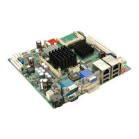
Mini-ITX Motherboard with Intel Atom CPU, UPS Battery Backup, DDR2, VGA, DVI, LVDS, HDTV, Dual PCIe GbE, Compact Flash , Dual SATA and PCIe Mini
Brand:
IEI Technology
| Category:
Motherboard
| Size: 0.15 MB
Table of Contents
Quick Installation Guide
1
Specifications
2
Ordering Information
3
Board Layout
13
Advertisement
Related Products
IEI Technology eKINO-BT
IEI Technology WAFER - E668EV ATX
IEI Technology WAFER - E668EV AT
IEI Technology EB-5800
IEI Technology eNOVA-945GSE
IEI Technology EP-267-GM45
IEI Technology ECK-3692
IEI Technology eMerge Enterprise
IEI Technology eMerge Enterprise Ultra
IEI Technology ECW-281B2-D525
IEI Technology Categories
Motherboard
Touch Panel
Computer Hardware
Single board computers
Desktop
More IEI Technology Manuals
Login
Sign In
OR
Sign in with Facebook
Sign in with Google
Upload manual
Upload from disk
Upload from URL