Sign In
Upload
Manuals
Brands
IEI Technology Manuals
Industrial PC
ECW-281B-945GSE
IEI Technology ECW-281B-945GSE Manuals
Manuals and User Guides for IEI Technology ECW-281B-945GSE. We have
1
IEI Technology ECW-281B-945GSE manual available for free PDF download: User Manual
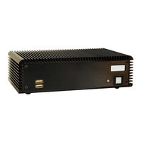
IEI Technology ECW-281B-945GSE User Manual (167 pages)
INTEL ATOM FANLESS EMBEDDED SYSTEM
Brand:
IEI Technology
| Category:
Industrial PC
| Size: 4 MB
Table of Contents
Table of Contents
5
1 Introduction
17
Ecw-281B-945Gse Embedded System Overview
18
ECW-281B-945GSE Benefits
18
Figure 1-1: ECW-281B-945GSE Series Embedded System
18
Table 1-1: Model Variations
19
Table 1-2: Technical Specifications
21
Power Module Options
22
Power Module Specifications
22
Technical Specifications
20
ECW-281B-945GSE Features
19
Ecw-281B-945Gse Model Variations
19
Table 1-3: ECW-281B-945GSE Power Module Options
22
Figure 1-2: Power Adapter
23
Power Adapter
23
Table 1-4: DC-To-DC Power Module Specifications
23
Table 1-5: Power Adapter Specifications
24
2 Mechanical Description
25
Ecw-281B-945Gse Mechanical Overview
26
Physical Dimensions
26
ECW-281B-945GSE Dimensions
26
Figure 2-1: ECW-281B-945GSE Dimensions (MM)
27
Motherboard Dimensions
27
Figure 2-3: Power Module Dimensions (MM)
28
Figure 2-2: WAFER SBC Dimensions (MM)
28
Figure 2-4: ECW-281B-945GSE Front Panel
29
Bottom Surface
30
Figure 2-5: ECW-281B-945GSE Rear Panel
30
Figure 2-6: Bottom Surface
31
Internal Overview
31
Power Module Dimensions
28
External Overview
29
Front Panel
29
Rear Panel
29
Figure 2-7: Internal Overview
32
3 System Components
33
Ecw-281B-945Gse Embedded System Motherboard
34
Figure 3-1: WAFER-945GSE Jumper and Connector Locations
34
WAFER-945GSE Motherboard Overview
34
Table 3-1: Peripheral Interface Connectors
36
Table 3-2: ATX Power Connector Pinouts
37
Audio Connector (10-Pin)
38
ATX Power Supply Enable Connector
37
CPU Support
35
Peripheral Interface Connectors
35
Internal Peripheral Connectors
36
ATX Power Connector
36
Figure 3-2: ATX Power Connector Location
37
Figure 3-3: ATX Power Supply Enable Connector Location
38
Table 3-3: ATX Power Supply Enable Connector Pinouts
38
Figure 3-13: USB Connector Pinout Locations
49
Figure 3-14: ECW-281B-945GSE External Peripheral Interface Connector
50
Table 3-13: USB Port Connector Pinouts
50
Figure 3-15: RJ-45 Ethernet Connector
51
Table 3-16: RS-232 Serial Port (COM 1) Pinouts
52
USB Connectors
52
Figure 3-18: Jumpers
54
WAFER-945GSE Motherboard On-Board Jumpers
54
Figure 3-19: CF Card Setup Jumper Location
55
Table 3-20: CF Card Setup Jumper Settings
55
Figure 3-20: Clear CMOS Jumper
56
Table 3-21: Clear CMOS Jumper Settings
56
COM 2 Function Select Jumper
57
Figure 3-21: COM 2 Function Select Jumper Location
57
Table 3-22: COM 2 Function Select Jumper Settings
57
ATX Mode Connector
58
Connector Mappings
58
Power Connector
58
Serial Port Connector (COM1)
51
Table 3-14: LAN Pinouts
51
Table 3-15: RJ-45 Ethernet Connector Leds
51
Figure 3-16: COM1 Pinout Locations
52
Figure 3-17: VGA Connector
53
Table 3-17: USB Port Pinouts
53
VGA Connector
53
Table 3-18: VGA Connector Pinouts
54
Table 3-19: Jumpers
54
CF Card Setup
55
Clear CMOS Jumper
55
Compactflash® Socket
39
Figure 3-4: Audio Connector Pinouts (10-Pin)
39
Figure 3-5: CF Card Socket Location
40
Table 3-7: Pcie Mini Card Slot Pinouts
43
Figure 3-11: COM3 to COM6 Connector Pinout Locations
47
Figure 3-12: Serial Port Connector Location
48
Serial Port Connector (COM 2)
48
Table 3-11: COM3 to COM6 Connector Pinouts
48
Table 3-12: Serial Port Connector Pinouts
49
USB Connectors (Internal)
49
External Peripheral Interface Connector Panel
50
LAN Connectors
50
Table 3-4: Audio Connector Pinouts (10-Pin)
39
Figure 3-8: Power Button Connector Location
44
Power Button Connector
44
Reset Button Connector
44
Table 3-8: Power Button Connector Pinouts
44
Figure 3-9: Reset Button Connector Locations
45
SATA Drive Connectors
45
Table 3-9: Reset Button Connector Pinouts
45
Figure 3-10: SATA Drive Connector Locations
46
Serial Port Connector (COM3, COM4, COM5 and COM6)
46
Table 3-10: SATA Drive Connector Pinouts
46
Figure 3-6: LED Connector Locations
41
LED Connector
41
Table 3-5: CF Card Socket Pinouts
41
Figure 3-7: Pcie Mini Card Slot Location
42
Pcie Mini Card Slot
42
Table 3-6: LED Connector Pinouts
42
Table 3-23: Motherboard Power Connector Mapping
58
4 Installation
59
Anti-Static Precautions
60
Installation Procedure
60
Installation Procedure Overview
60
Unpacking
61
Table 4-1: Package List Contents
62
Bottom Surface Removal
63
Configure the Jumper Settings
63
Figure 4-1: Bottom Surface Retention Screws
63
Figure 4-2: Hard Drive Bracket
64
Figure 4-3:HDD Bracket Retention Screws
64
Figure 4-4: HDD Retention Screws
65
Figure 4-5: HDD Thermal Pad
66
Figure 4-6: Mounting Bracket Retention Screws
67
Mounting the System with Wall Mount Kit
67
Figure 4-7: Wall-Mounting Bracket
68
DIN Mounting
69
Mounting the System with Mounting Brackets
66
Hard Drive Installation
64
Figure 4-8: Mount the Embedded System
69
Figure 4-9: DIN Rail Mounting Bracket
70
Figure 4-12: Secure the Assembly to the DIN Rail
71
Figure 4-11: Mounting the DIN RAIL
71
Figure 4-13: Wireless Antenna Installation
72
Power-On Procedure
73
Terminal Block Pinouts
73
Figure 4-10: Screw Locations
70
Wireless Antenna Installation (Wireless Models Only)
71
Cable Connections
72
Power-On Procedure
72
Installation Checklist
72
Figure 4-14: Terminal Block Pinouts
73
Figure 4-15: Power Button
74
5 Bios Screens
75
Introduction
76
Starting Setup
76
Using Setup
76
Getting Help
77
Unable to Reboot after Configuration Changes
77
BIOS Menu Bar
77
Main
78
Advanced
79
CPU Configuration
80
IDE Configuration
81
IDE Master, IDE Slave
83
Super IO Configuration
89
Hardware Health Configuration
93
Power Configuration
97
ACPI Configuration
97
APM Configuration
98
Menu 10:Advanced Power Management Configuration
99
Remote Configuration
101
Menu 11: Remote Access Configuration [Advanced]
102
USB Configuration
105
Menu 12: USB Configuration
106
Pci/Pnp
107
Menu 13: Pci/Pnp Configuration
108
Boot
110
Boot Settings Configuration
110
Menu 15: Boot Settings Configuration
111
Boot Device Priority
113
Security
114
Chipset
115
North Bridge Chipset Configuration
116
Southbridge Configuration
119
Exit
120
6 Software Drivers
122
Available Software Drivers
123
Starting the Driver Program
123
Chipset Driver Installation
124
Figure 6-1: Drivers
124
Figure 6-2: Chipset Driver Screen
125
Figure 6-3: Chipset Driver Welcome Screen
125
Figure 6-4: Chipset Driver License Agreement
126
Figure 6-5: Chipset Driver Read Me File
127
Figure 6-6: Chipset Driver Setup Operations
128
Figure 6-7: Chipset Driver Installation Finish Screen
129
Vga Driver Installation
129
Figure 6-9: VGA Driver Setup Files Extracted
130
Figure 6-8: VGA Driver Read Me File
130
Figure 6-10: VGA Driver Welcome Screen
131
Figure 6-14: VGA Driver Installation Finish Screen
134
Figure 6-15: LAN Driver Welcome Screen
135
Figure 6-16: LAN Driver Welcome Screen
135
Figure 6-17: LAN Driver Installation
136
Audio Driver Installation
137
Figure 6-12: VGA Driver Read Me File
132
Figure 6-11: VGA Driver License Agreement
132
Figure 6-13: VGA Driver Setup Operations
133
Lan Driver Installation
134
Figure 6-18: LAN Driver Installation Complete
137
Figure 6-19: Audio Driver Options
138
Figure 6-20: AC'97 Driver Installation File Extraction
138
Figure 6-21: AC'97 Driver Installation Welcome Screen
139
Figure 6-22: AC'97 Driver Installation Verification
140
Figure 6-23: AC'97 Driver Installation
140
Figure 6-24: AC'97 Driver Installation Complete
141
7 Troubleshooting and Maintenance
142
Ecw-281B-945Gse System Maintenance Overview
143
System Troubleshooting
143
The System Doesn't Turn on
143
The System Doesn't Boot up
144
More Troubleshooting
145
Component Replacement Procedure
145
SO-DIMM Replacement
146
Figure 7-1: SO-DIMM Cover Plate
146
Figure 7-2: SO-DIMM Installation
147
Asafety Precautions
148
Safety Precautions
149
General Safety Precautions
149
Anti-Static Precautions
150
Maintenance and Cleaning Precautions
150
Maintenance and Cleaning
150
Cleaning Tools
151
Iei Embedded System Series
152
Iei Embedded
153
Series
153
Overview
153
IEI Embedded System Series
153
IEI Embedded System Series Variations
154
Embedded System Solutions
154
AMD ® Geode
154
LX800 500Mhz Solutions
154
AMD ® Geode
155
1Ghz Solutions
155
VIA MARK ® 800Mhz Solutions
156
Intel ® Celeron
156
Intel Celeron M 1.5Ghz Solutions
157
Intel
157
Intel
158
Pentium
158
Socket 479 Pentium ® /Celeron
158
D Solutions
159
LGA 775 Intel
159
Intel Socket 479 Core Duo/Solo Solutions
160
GX466 333Mhz Solutions
155
Via ® Luke
155
Cbios Menu Options
161
Bios Configuration Options
162
Dwatchdog Timer
165
Advertisement
Advertisement
Related Products
IEI Technology ECW-281B-R21/N270 ECW-281B2-R21/N270
IEI Technology ECW-281B-D525
IEI Technology ECW-281B2-D525
IEI Technology ECK-161B
IEI Technology ECN-360A-ULT3
IEI Technology ECN-380-QM87
IEI Technology ECN-360A-ULT3-C/4G-R10
IEI Technology ECN-360A-ULT3-i5/4G-R10
IEI Technology ECN-360A-ULT3-CE/4G-R10
IEI Technology ECN-380-QM87i
IEI Technology Categories
Motherboard
Touch Panel
Computer Hardware
Single board computers
Desktop
More IEI Technology Manuals
Login
Sign In
OR
Sign in with Facebook
Sign in with Google
Upload manual
Upload from disk
Upload from URL