Sign In
Upload
Manuals
Brands
IEI Technology Manuals
Computer Hardware
Enano-8523T
IEI Technology Enano-8523T Manuals
Manuals and User Guides for IEI Technology Enano-8523T. We have
1
IEI Technology Enano-8523T manual available for free PDF download: User Manual
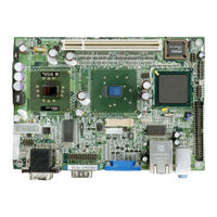
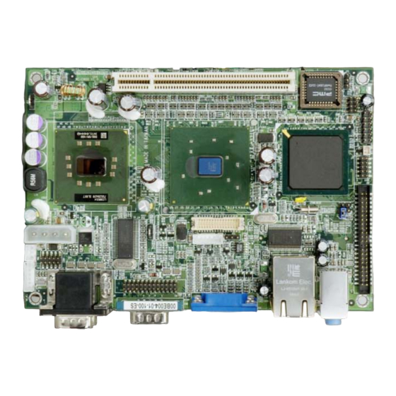
IEI Technology Enano-8523T User Manual (164 pages)
ULV Intel Celeron M 800 MHZzero cache with COM ports, USB 2.0 and TPM 1.2 security function support
Brand:
IEI Technology
| Category:
Computer Hardware
| Size: 8 MB
Table of Contents
Table of Contents
3
1 Introduction
13
Enano-8523T Board Overview
14
Enano-8523T Board Variations
14
Enano-8523T Board Applications
14
Enano-8523T Board Benefits
14
Enano-8523T Board Features
15
Enano-8523T Board Overview
16
Figure 1-1: Enano-8523T Board Overview (Top View)
16
Enano-8523T Board Connectors
17
Figure 1-2: Enano-8523T Board Overview (Bottom View)
17
Technical Specifications
18
Table 1-1: Technical Specifications
19
2 Detailed Specifications
21
Cpu Support
22
Onboard Chipsets
22
Northbridge and Southbridge Chipsets
22
Intel® 852GM Northbridge Chipset
22
Intel® ICH4 Southbridge Chipset
23
Data Flow
24
Figure 2-1: Data Flow Block Diagram
24
Graphics Support
25
Memory Support
26
Tpm Support
26
Pci Bus Interface Support
27
10/100 Base-T Internet
28
Ide Device Support
28
Real Time Clock
28
System Monitoring
28
Usb Interfaces
29
Bios
29
Operating Temperature and Temperature Control
29
Audio Codec
30
Power Consumption
31
Packaged Contents and Optional Accessory Items
31
Package Contents
31
Table 2-1: Power Consumption
31
3 Connectors and Jumpers
33
Peripheral Interface Connectors
34
Enano-8523T Board Layout
34
Figure 3-1: Connector and Jumper Locations (Top Side)
34
Peripheral Interface Connectors
35
Figure 3-2: Connector and Jumper Locations (Bottom Side)
35
Rear Panel Connectors
36
Onboard Jumpers
36
Table 3-1: Peripheral Interface Connectors
36
Table 3-2: Peripheral Interface Connectors
36
Internal Peripheral Connectors
37
IDE Connector
37
Table 3-3: Onboard Jumpers
37
DIO Connector
38
Figure 3-3: IDE Connector Location
38
Table 3-4: IDE Connector Pinouts
38
Battery Connector
39
Figure 3-4: DIO Connector Location
39
Table 3-5: DIO Connector Pinouts
39
Front Panel Connector
40
Figure 3-5: Battery Connector Location
40
Table 3-6: Front Panel Connector Pinouts
40
USB Connector
41
Figure 3-6: Front Panel Connector Location
41
Table 3-7: USB Connector Pinouts
41
Fan Connector
42
Figure 3-7: USB Connector Location
42
Table 3-8: FAN1 Pinouts
42
ATX Power Connector
43
Figure 3-8: Table 3-9: FAN1 Connector Location
43
Table 3-10: Power Connector Pinouts
43
Power Connector
44
Figure 3-9: Power Connector Location
44
Table 3-11: Power Connector Pinouts
44
Keyboard/Mouse Connector
45
Figure 3-10: Power Connector Location
45
Table 3-12: Keyboard/Mouse Connector Pinouts
45
COM4 Connectors
46
Figure 3-11: Keyboard/Mouse Connector Location
46
Table 3-13: COM4 Connector Pinouts
46
Parallel Port Connector
47
Figure 3-12: COM4 Connector Location
47
Inverter Connector
48
Figure 3-13: Parallel Port Connector Location
48
Table 3-14: Parallel Port Connector Pinouts
48
Figure 3-14: Inverter Connector
49
Table 3-15: Inverter Connector Pinouts
49
LVDS Connector
50
Table 3-16: LVDS Connector Pinouts
50
SODIMM Socket
51
Figure 3-15: LVDS Connector
51
Compact Flash Type 2 Socket
52
Figure 3-16: SODIMM Socket Location (Rear Side)
52
Figure 3-17: CFII Socket Location (Rear Side)
53
Table 3-17: CFII Socket Pinouts
53
External (Rear Panel) Connectors
54
Serial Port Connectors
54
Figure 3-18: Enano-8523T Board Rear Panel
54
USB Connectors
55
Ethernet Connector
55
Table 3-18: Serial Port Pinouts
55
Table 3-19: USB Connectors
55
VGA Connector
56
Figure 3-19: RJ-45 Ethernet Connector
56
Table 3-20: RJ-45 Ethernet Connector Pinouts
56
Table 3-21: RJ-45 Ethernet Connector Leds
56
Audio Connector
57
Table 3-22: VGA Connector Pinouts
57
Jumpers
58
Figure 3-21: Jumper Locations
58
Reset CMOS Jumper
59
CF Card Setup
59
Table 3-23: JP2 Jumper Settings
59
LCD Voltage Setup
60
Table 3-24: JP4 Jumper Settings
60
Table 3-25: JP6 Jumper Settings
60
4 Installation and Configuration
61
Installation Considerations
62
Installation Notices
62
Unpacking
63
Unpacking Precautions
63
Checklist
63
Enano-8523T Board Installation
64
Preinstalled Components
64
Components to Install
65
DIMM Module Installation
65
Purchasing the Memory Module
65
Peripheral Device Connection
66
IDE Disk Drive Connector (IDE1)
66
Table 4-1: IEI Provided Cables
66
Keyboard/Mouse Connection
67
Chassis Installation
67
Rear Panel Connectors
67
LCD Panel Connection
67
Ethernet Connection
67
USB Connection
68
5 Ami Bios Setup
69
Introduction
70
Starting Setup
70
Using Setup
70
Getting Help
71
Unable to Reboot after Configuration Changes
71
BIOS Menu Bar
71
Table 5-1: BIOS Navigation Keys
71
Main
72
Advanced
73
CPU Configuration
74
IDE Configuration
75
Menu 4: IDE Configuration
76
IDE Master, IDE Slave
77
Menu 5: IDE Master and IDE Slave Configuration
78
Super IO Configuration
83
Hardware Health Configuration
87
Menu 7: Hardware Health Configuration
88
ACPI Configuration
89
MPS Configuration
90
Trusted Computing
90
Menu 10: Trusted Computing
91
USB Configuration
92
Menu 11: USB Configuration
93
Menu 12: USB Mass Storage Device
95
Boot
96
Boot Settings Configuration
97
Boot Device Priority
99
Menu 15: Boot Device Priority Settings
100
Hard Disk Drives
101
Removable Drives
101
Menu 16: Removable Drives
103
CD/DVD Drives
104
Security
104
Menu 17: Security
105
Chipset
106
Northbridge Configuration
107
Menu 19:Northbridge Chipset Configuration
108
Power
113
Exit
114
Menu 21:Exit
115
6 Software Drivers
117
Available Software Drivers
118
Chipset Driver Installation
118
Figure 6-1: Installshield Wizard Preparation Screen
119
Figure 6-2: Welcome Screen
119
Figure 6-3: License Agreement
120
Figure 6-4: Readme Information
120
Realtek Audio Driver Installation
121
Figure 6-5: Restart the Computer
121
Figure 6-6: Audio Driver Install Shield Wizard Starting
122
Figure 6-7: Audio Driver Setup Preparation
122
Figure 6-8: Audio Driver Welcome Screen
123
Figure 6-9: Audio Driver Software Configuration
123
Figure 6-10: Audio Driver Digital Signal
124
Figure 6-11: Audio Driver Installation Begins
125
Intel Graphics Media Accelerator Driver
126
Figure 6-12: Audio Driver Installation Complete
126
Figure 6-13: GMA Driver Installation Welcome Screen
127
Figure 6-14: GMA Driver License Agreement
128
Figure 6-15: GMA Driver Installing Notice
128
Lan Driver Installation
129
Figure 6-16: GMA Driver Installation Complete
129
Figure 6-17: LAN License Agreement
130
Figure 6-18: Select the Driver Directory
130
Figure 6-19: LAN Driver Configuration
131
Abios Configuration Options
133
Bios Configuration Options
134
Bwatchdog Timer
137
Example Program
139
Caddress Mapping
141
Io Address Map
142
St Mb Memory Address Map
142
Addres Map
142
Irq Mapping Table
143
Dma Channel Assignments
143
Dexternal Ac'97 Audio Codec
145
Introduction
146
Driver Installation
146
Sound Effect Configuration
147
Sound Effect
148
Environment Simulation
149
Karaoke Mode
150
Equalizer Selection
151
Speaker Configuration
152
Speaker Test
153
S/PDIF-In & S/PDIF-Out
154
Connector Sensing
154
Hrtf Demo
157
Microphone Effect
157
General
158
D.14 G Eneral
158
Eindex
159
Advertisement
Advertisement
Related Products
IEI Technology ECN-680A-H61
IEI Technology ECN-360A-D2550
IEI Technology ECN-360A-D2550/2G-R10
IEI Technology ECN-360AW-D2550/2G-R10
IEI Technology eNOVA-945GSE
IEI Technology EP-308A
IEI Technology ECW-281BB6
IEI Technology ECW-281B-R21/N270 ECW-281B2-R21/N270
IEI Technology ECA-100
IEI Technology ECK-1000 Series
IEI Technology Categories
Motherboard
Touch Panel
Computer Hardware
Single board computers
Desktop
More IEI Technology Manuals
Login
Sign In
OR
Sign in with Facebook
Sign in with Google
Upload manual
Upload from disk
Upload from URL