Sign In
Upload
Manuals
Brands
IEI Technology Manuals
Industrial PC
ECW-281B-R21/N270 ECW-281B2-R21/N270
IEI Technology ECW-281B-R21/N270 ECW-281B2-R21/N270 Manuals
Manuals and User Guides for IEI Technology ECW-281B-R21/N270 ECW-281B2-R21/N270. We have
1
IEI Technology ECW-281B-R21/N270 ECW-281B2-R21/N270 manual available for free PDF download: User Manual
IEI Technology ECW-281B-R21/N270 ECW-281B2-R21/N270 User Manual (179 pages)
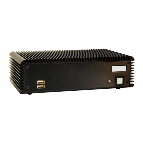
IEI Intel Atom? Fanless Embedded System RoHS Compliant, Dual GbE LAN, COM Ports, USB 2.0
Brand:
IEI Technology
| Category:
Industrial PC
| Size: 7 MB
Table of Contents
Table of Contents
5
Introduction
17
Overview
18
Benefits
18
Features
18
Figure 1-1: ECW-281B/281B2-R21/N270 Series Embedded System
18
Model Variations
19
Table 1-1: Model Variations
19
Technical Specifications
20
Power Module Specifications
21
Power Module Options
21
Table 1-2: Technical Specifications
21
Table 1-3: ECW-281B/281B2-R21/N270 Power Module Options
21
Table 1-4: DC-To-DC Power Module Specifications
22
Power Adapter
23
Figure 1-2: Power Adapter
23
Table 1-5: Power Adapter Specifications
23
Mechanical Description
24
Mechanical Overview
25
Physical Dimensions
25
System Dimensions
25
Motherboard Dimensions
26
F Igure 2-1: ECW-281B/281B2-R21/N270 Dimensions
26
Power Module Dimensions
27
F Igure 2-2: WAFER SBC Dimensions
27
F Igure 2-3: Power Module Dimensions
27
External Overview
28
Front Panel
28
Rear Panel
28
ECW-281B-R21/N270 Rear Panel
28
Figure 2-4: ECW-281B/281B2-R21/N270 Front Panel
28
ECW-281B2-R21/N270 Rear Panel
29
Figure 2-5: ECW-281B-R21/N270 Rear Panel
29
Bottom Surface
30
Figure 2-6: ECW-281B2-R21/N270 Rear Panel
30
Internal Overview
31
Figure 2-8: Internal Overview
32
System Components
33
Embedded System Motherboard
34
WAFER-945GSE Motherboard Overview
34
Figure 3-1: WAFER-945GSE Jumper and Connector Locations
34
CPU Support
35
Peripheral Interface Connectors
35
Table 3-1: Peripheral Interface Connectors
36
I Nternal P Eripheral C Onnectors 2
36
Figure 3-2: ATX Power Connector Location
37
Table 3-2: ATX Power Connector Pinouts
37
ATX Power Supply Enable Connector 2
37
Figure 3-3: ATX Power Supply Enable Connector Location
38
Figure 3-4: Audio Connector Pinouts (10-Pin)
38
Table 3-3: ATX Power Supply Enable Connector Pinouts
38
Figure 3-5: CF Card Socket Location
39
Table 3-4: Audio Connector Pinouts (10-Pin)
39
Compactflash® Socket 2
39
Table 3-5: CF Card Socket Pinouts
40
LED Connector 2
40
Figure 3-6: LED Connector Locations
41
Table 3-6: LED Connector Pinouts
41
Pcie Mini Card Slot 2
41
Figure 3-7: Pcie Mini Card Slot Location
42
Figure 3-8: Power Button Connector Location
43
Table 3-7: Pcie Mini Card Slot Pinouts
43
Table 3-8: Power Button Connector Pinouts
43
Figure 3-9: Reset Button Connector Locations
44
Table 3-9: Reset Button Connector Pinouts
44
Figure 3-10: SATA Drive Connector Locations
45
Table 3-10: SATA Drive Connector Pinouts
45
Serial Port Connector (COM3, COM4, COM5 and COM6) 2
45
Figure 3-11: COM3 to COM6 Connector Pinout Locations
46
Table 3-11: COM3 to COM6 Connector Pinouts
47
Serial Port Connector (COM 2)(RS-232, RS-422 or RS-485) 3
47
Figure 3-12: RS-232/422/485 Serial Port Connector Location
48
Table 3-12: RS-232/RS-485 Serial Port Connector Pinouts
48
USB Connectors (Internal) 3
48
Figure 3-13: USB Connector Pinout Locations
49
Table 3-13: USB Port Connector Pinouts
49
E Xternal P Eripheral I Nterface C Onnector P Anel 3
49
Figure 3-14: ECW-281B/281B2-R21/N270 External Peripheral Interface Connector
50
Figure 3-15: RJ-45 Ethernet Connector
50
Table 3-14: LAN Pinouts
50
LAN Connectors 3
50
Figure 3-16: COM1 Pinout Locations
51
Table 3-15: RJ-45 Ethernet Connector Leds
51
Table 3-16: RS-232 Serial Port (COM 1) Pinouts
51
Serial Port Connector (COM1) 3
51
Figure 3-17: VGA Connector
52
Table 3-17: USB Port Pinouts
52
USB Connectors 3
52
Figure 3-18: Jumpers
53
Table 3-18: VGA Connector Pinouts
53
Wafer-945Gse M Otherboard O N - Board J Umpers 3
53
Figure 3-19: CF Card Setup Jumper Location
54
Table 3-19: Jumpers
54
Table 3-20: CF Card Setup Jumper Settings
54
Figure 3-20: Clear CMOS Jumper
55
Table 3-21: Clear CMOS Jumper Settings
55
Figure 3-21: COM 2 Function Select Jumper Location
56
Table 3-22: COM 2 Function Select Jumper Settings
56
COM 2 Function Select Jumper (ECW-281B-R21 Series Only) 4
56
Table 3-23: Motherboard Power Connector Mapping
57
Table 3-24: Motherboard Power Connector Mapping
57
Installation 4
58
A Nti - Static P Recautions 4
59
Unpacking 4
60
Figure 4-1: Bottom Surface Retention Screws
61
Table 4-1: Package List Contents
61
Bottom Surface Removal 4
61
Figure 4-2: Hard Drive Bracket
62
Configure the Jumper Settings 4
62
Figure 4-3:HDD Bracket Retention Screws
63
Figure 4-4: HDD Retention Screws
63
Figure 4-5: HDD Thermal Pad
64
Figure 4-6: Mounting Bracket Retention Screws
65
Mounting the System with Mounting Brackets 4
65
Figure 4-7: Wall-Mounting Bracket
66
Figure 4-8: Mount the Embedded System
67
DIN Mounting 5
67
Figure 4-9: DIN Rail Mounting Bracket
68
Figure 4-10: Screw Locations
68
Figure 4-11: Mounting the DIN RAIL
69
Figure 4-12: Secure the Assembly to the DIN Rail
69
Wireless Antenna Installation (Wireless Models Only) 5
69
Figure 4-13: Wireless Antenna Installation
70
Cable Connections 5
70
Figure 4-14: Terminal Block Pinouts
71
Figure 4-15: Power Button
72
Getting Help 5
75
Table 5-1: BIOS Navigation Keys
75
CPU Configuration 6
77
IDE Configuration 6
79
IDE Master, IDE Slave 6
81
Super IO Configuration 7
86
Hardware Health Configuration 7
89
Power Configuration 7
93
APM Configuration 7
94
Remote Configuration 8
97
USB Configuration 8
100
Pci/Pnp
102
Bios Screens 5
73
I Ntroduction 5
74
Boot
104
Boot Settings Configuration 8
105
Boot Device Priority 9
107
Chipset
110
Figure 6-1: Drivers
119
Figure 6-2: Chipset Driver Screen
120
Figure 6-3: Chipset Driver Welcome Screen
120
Figure 6-4: Chipset Driver License Agreement
121
Figure 6-5: Chipset Driver Read Me File
122
Figure 6-6: Chipset Driver Setup Operations
122
Figure 6-7: Chipset Driver Installation Finish Screen
123
Figure 6-8: VGA Driver Read Me File
124
Figure 6-9: VGA Driver Setup Files Extracted
124
Figure 6-10: VGA Driver Welcome Screen
125
Figure 6-11: VGA Driver License Agreement
126
Figure 6-12: VGA Driver Read Me File
126
Figure 6-13: VGA Driver Setup Operations
127
Figure 6-14: VGA Driver Installation Finish Screen
127
Figure 6-15: LAN Driver Welcome Screen
128
Figure 6-16: LAN Driver Welcome Screen
129
Figure 6-17: LAN Driver Installation
129
Figure 6-18: LAN Driver Installation Complete
130
Figure 6-19: Audio Driver Options
131
Figure 6-20: AC'97 Driver Installation File Extraction
131
Figure 6-21: AC'97 Driver Installation Welcome Screen
132
Figure 6-22: AC'97 Driver Installation Verification
132
Figure 6-23: AC'97 Driver Installation
133
Figure 6-24: AC'97 Driver Installation Complete
133
Figure 7-1: SO-DIMM Cover Plate
138
Figure 7-2: SO-DIMM Installation
139
Figure B-1: IEI One Key Recovery Tool Menu
146
Figure B-2: Launching the Recovery Tool
150
Figure B-3: Recovery Tool Setup Menu
151
Figure B-4: Command Mode
151
Figure B-5: Partition Creation Commands
152
Figure B-6: Launching the Recovery Tool
154
Figure B-7: System Configuration for Windows
154
Figure B-8: Build-Up Recovery Partition
155
Figure B-9: Press any Key to Continue
155
Figure B-10: Press F3 to Boot into Recovery Mode
156
Figure B-11: Recovery Tool Menu
156
Figure B-12: about Symantec Ghost Window
157
Figure B-13: Symantec Ghost Path
157
Figure B-14: Select a Local Source Drive
158
Figure B-15: Select a Source Partition from Basic Drive
158
F Igure B-16: File Name to Copy Image
159
Figure B-17: Compress Image
159
Figure B-18: Image Creation Confirmation
160
Figure B-19: Image Creation Process
160
Figure B-20: Image Creation Complete
160
Figure B-21: Press any Key to Continue
161
Figure B-22: Partitions for Linux
162
Figure B-23: System Configuration for Linux
163
Figure B-24: Access Menu.lst in Linux (Text Mode)
163
Figure B-25: Recovery Tool Menu
164
Figure B-26: Recovery Tool Main Menu
165
Figure B-27: Restore Factory Default
166
Figure B-28: Recovery Complete Window
166
Figure B-29: Backup System
167
Figure B-30: System Backup Complete Window
167
Figure B-31: Restore Backup
168
Figure B-32: Restore System Backup Complete Window
168
Figure B-33: Symantec Ghost Window
169
Advertisement
Advertisement
Related Products
IEI Technology ECW-281B-945GSE
IEI Technology ECW-281B-D525
IEI Technology ECW-281B2-D525
IEI Technology ECK-161B
IEI Technology ECN-360A-ULT3
IEI Technology ECN-380-QM87
IEI Technology ECN-360A-ULT3-C/4G-R10
IEI Technology ECN-360A-ULT3-i5/4G-R10
IEI Technology ECN-360A-ULT3-CE/4G-R10
IEI Technology ECN-380-QM87i
IEI Technology Categories
Motherboard
Touch Panel
Computer Hardware
Single board computers
Desktop
More IEI Technology Manuals
Login
Sign In
OR
Sign in with Facebook
Sign in with Google
Upload manual
Upload from disk
Upload from URL