Sign In
Upload
Manuals
Brands
IEI Technology Manuals
Computer Hardware
ECN-680A-H61
IEI Technology ECN-680A-H61 Manuals
Manuals and User Guides for IEI Technology ECN-680A-H61. We have
1
IEI Technology ECN-680A-H61 manual available for free PDF download: User Manual
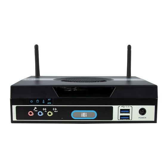
IEI Technology ECN-680A-H61 User Manual (190 pages)
Embedded System with 2nd Gen Intel Core i7/i5/i3 Desktop Processors, Dual DVI, HDMI, GbE, Two USB 3.0, Four USB 2.0, Four COM and RoHS Compliant
Brand:
IEI Technology
| Category:
Computer Hardware
| Size: 7 MB
Table of Contents
Table of Contents
4
1 Introduction
15
Overview
16
Model Variations
16
Table 1-1: Model Variations
16
Features
17
Technical Specifications
17
Front Panel
19
Figure 1-2: ECN-680A-H61 Front Panel
19
Table 1-2: Technical Specifications
19
Figure 1-3: LED Indicators
20
LED Indicators
20
Table 1-3: LED Indicators
20
Rear Panel
21
Figure 1-4: ECN-680A-H61 Rear Panel
22
Dimensions
23
Figure 1-5: Physical Dimensions (MM)
23
2 Unpacking
24
Anti - Static Precautions
25
Unpacking Precautions
25
Unpacking Checklist
26
Table 2-1: Package List Contents
27
3 Installation
28
Installation Precautions
29
Installation and Configuration Steps
29
Memory Module Installation
30
Figure 3-1: Retention Screws Removal
30
Figure 3-2: Fan Removal
30
Figure 3-3: SO-DIMM Socket Location
31
Figure 3-4: DDR3 SO-DIMM Module Installation
31
Cpu Installation
32
Figure 3-5: CPU Socket Location
32
Figure 3-6: Disengage the CPU Socket Load Lever
33
Figure 3-7: Remove Protective Cover
33
Figure 3-8: Insert the CPU
34
Hard Disk Drive (Hdd) Installation
35
Figure 3-9: Close the CPU Socket
35
Figure 3-10: HDD Cover Retention Screws
36
Figure 3-11: HDD Bracket Retention Screws
36
Figure 3-12: Inserting the HDD
37
Figure 3-13: HDD Retention Screws
37
W I -F I Antenna Installation (W I -F I Model Only )
38
At/Atx Mode Selection
38
Figure 3-14: Wi-Fi Antenna Installation
38
AT Power Mode
39
ATX Power Mode
39
Figure 3-15: AT/ATX Switch Location
39
Reset the System
40
Powering O N /Off the System
40
Figure 3-16: Reset Button Location
40
Mount the System
41
Figure 3-17: Power Button Location
41
Figure 3-18: Mounting Screw Holes
41
Figure 3-19: Mounting Bracket Retention Screws
42
Mounting the System with Mounting Brackets
42
External Peripheral Interface Connectors
43
Figure 3-20: Peripheral Connectors (Front Panel)
44
Figure 3-21: Peripheral Connectors (Rear Panel)
44
Audio Connector
45
Figure 3-22: Audio Connector
45
DVI Display Device Connection
46
Figure 3-23: DVI Connector
46
Figure 3-24: HDMI Connection
47
HDMI Device Connection
47
LAN Connection
47
Figure 3-25: LAN Connection
48
Serial Port Connection
48
Figure 3-26: DB-9 Serial Port Connector
49
Figure 3-27: DB-9 Connector Pinout Location
49
Table 3-1: RS-232 Serial Ports Pinouts (COM2)
49
Figure 1-1: ECN-680A-H61
50
Serial Port Connection
50
Table 3-2: RS-232 Serial Ports Pinouts (COM3)
50
Table 3-3: RS-422/485 Serial Port Pinouts (COM4)
50
Figure 3-28: RJ-45 Serial Port Connector
51
Figure 3-29: RJ-45 RS-232 Serial Port Pinout Location
51
Table 3-4: RS-232 Serial Ports Pinouts (COM1)
51
Figure 3-30: DB-9 Connector Pinout Location
52
Table 3-5: DB-9 Serial Ports Pinouts
52
USB Device Connection
52
Figure 3-31: USB Device Connection
53
4 System Motherboard
54
Overview
55
Figure 4-1: Connector and Jumper Locations (Front Side)
55
Layout
55
Connectors
56
Figure 4-2: Connector and Jumper Locations (Rear Side)
56
Peripheral Interface Connectors
56
Battery Connector
57
I Nternal P Eripheral C Onnectors
57
Table 4-1: Peripheral Interface Connectors
57
Fan Connector (CPU)
58
Figure 4-3: Battery Connector Location
58
Table 4-2: Battery Connector Pinouts
58
Figure 4-4: CPU Fan Connector Location
59
LED Module Connector
59
Table 4-3: CPU Fan Connector Pinouts
59
Figure 4-5: LED Module Connector Location
60
Logo LED Connectors
60
Table 4-4: LED Module Connector Pinouts
60
Figure 4-6: Logo LED Connector Locations
61
Pcie Mini Card Slot
61
Table 4-5: Logo LED Connector Pinouts
61
Figure 4-7: Pcie Mini Card Slot Location
62
Figure 4-8: RS-232 Serial Port Connector Location
63
Serial Port Connectors
63
Table 4-6: Pcie Mini Card Slot Pinouts
63
Figure 4-9: RS-422/485 Serial Port Connector Location
64
RS-422/485 Serial Port Connector
64
Table 4-7: Serial Port Connector Pinouts (COM2)
64
Table 4-8: Serial Port Connector Pinouts (COM3)
64
Figure 4-10: SATA Drive Connector Locations
65
SATA Drive Connectors
65
Table 4-10: SATA Drive Connector Pinouts
65
Table 4-9: RS-422/485 Serial Port Connector Pinouts
65
Figure 4-11: SATA Power Connector Locations
66
SATA Power Connectors
66
Smbus Connector
66
Table 4-11: SATA Power Connector Pinouts
66
Figure 4-12: Smbus Connector Location
67
SO-DIMM Connector
67
Table 4-12: Smbus Connector Pinouts
67
Figure 4-13: SO-DIMM Connector Locations
68
Figure 4-14: SPDIF Connector Location
68
Speaker Connector
68
Figure 4-15: SPI Flash Connector Location
69
SPI Flash Connector
69
Table 4-13: SPDIF Connector Pinouts
69
Table 4-14: SPI Flash Connector Pinouts
69
Figure 4-16: EC SPI Flash Connector Location
70
K Type Thermocouple Connectors
70
SPI Flash Connector (EC)
70
Table 4-15: EC SPI Flash Connector Pinouts
70
Figure 4-17: Type K Thermocouple Connector Locations
71
Table 4-16: Type K Thermocouple Connector Pinouts
71
USB 2.0 Connectors
71
Jumper Settings
72
Figure 4-18: USB Connector Locations
72
Table 4-17: USB Port Connector Pinouts
72
Clear CMOS
73
Figure 4-19: Clear CMOS Jumper Location
73
Table 4-18: Jumpers
73
Table 4-19: Clear CMOS Jumper Settings
73
5 Bios
74
Introduction
75
Starting Setup
75
Using Setup
75
BIOS Menu Bar
76
Getting Help
76
Table 5-1: BIOS Navigation Keys
76
Unable to Reboot after Configuration Changes
76
Main
77
BIOS Information
77
Iwdd Vendor
77
Iwdd Version
77
Memory Information
77
System Date [XX/XX/XX]
77
System Time [XX:XX:XX]
77
Advanced
78
ACPI Configuration
79
ACPI Sleep State [S1 (CPU Stop Clock)]
79
RTC Wake Settings
80
Wake System with Fixed Time [Disabled]
80
Trusted Computing
81
TPM Support [Disable]
81
CPU Configuration
82
Hyper-Threading [Enabled]
82
Intel Virtualization Technology [Enabled]
82
CPU Information
83
SATA Configuration
84
SATA Mode [IDE Mode]
84
Serial-ATA Controller 0 [Compatible]
84
USB Configuration
85
USB Devices
85
F81866 Super IO Configuration
86
Legacy USB Support Enabled
86
Serial Port [Enabled]
86
Serial Port N Configuration
87
Change Settings [Auto]
87
Serial Port [Enabled]
87
Change Settings [Auto]
89
Device Mode [RS422/485]
90
H/W Monitor
91
Serial Port Console Redirection
91
PC Health Status
91
Console Redirection Settings
92
Console Redirection
92
Terminal Type [ANSI]
93
Bits Per Second [115200]
93
I E I Feature
94
Chipset
95
Northbridge Configuration
96
Southbridge Configuration
97
WIFI Support [Enabled]
97
Intel IGD SWSCI Opregion
99
DVMT Mode Select [DVMT Mode]
99
DVMT Memory [Maximum]
99
IGD - Boot Type [VBIOS Default]
99
Boot
100
Bootup Numlock State [On]
100
Option ROM Messages [Force BIOS]
100
Launch PXE Boot [Disabled]
100
Security
102
Boot Option #1 [SATA PM: SAMSUNG
102
Hard Drive BBS Priorities
102
Administrator Password
102
HDD Security Configuration
103
User Password
103
Set User Password
103
Set Master Password
103
Exit
104
Save Changes and Exit
104
Discard Changes and Exit
104
Restore Defaults
104
Save as User Defaults
104
Restore User Defaults
105
6 Software Drivers
106
Available Software Drivers
107
Starting the Driver Program
107
Chipset Driver Installation
108
Figure 6-1: Drivers
108
Figure 6-2: Chipset Driver Screen
109
Figure 6-3: Chipset Driver Welcome Screen
109
Figure 6-4: Chipset Driver License Agreement
110
Figure 6-5: Chipset Driver Read Me File
111
Figure 6-6: Chipset Driver Setup Operations
111
Graphics Driver Installation
112
Figure 6-7: Chipset Driver Installation Finish Screen
112
Figure 6-8: Graphics Driver Read Me File
113
Figure 6-9: Graphics Driver Setup Files Extracted
113
Figure 6-10: Graphics Driver Welcome Screen
114
Figure 6-11: Graphics Driver License Agreement
114
Figure 6-12: Graphics Driver Read Me File
115
Figure 6-13: Graphics Driver Setup Operations
115
Lan Driver Installation
116
Figure 6-14: Graphics Driver Installation Finish Screen
116
Figure 6-15: Intel® Network Connection Menu
117
Figure 6-16: LAN Driver Welcome Screen
117
Figure 6-17: LAN Driver License Agreement
118
Figure 6-18: LAN Driver Setup Options
119
Figure 6-19: LAN Driver Installation
119
Audio Driver Installation
120
Figure 6-20: LAN Driver Installation Complete
120
Figure 6-21: Audio Driver Welcome Screen
121
Figure 6-22: Audio Driver Installation
121
W I -F I Driver Installation
122
Figure 6-23: Audio Driver Installation Complete
122
Figure 6-24: License Agreement
123
Figure 6-25: Setup Type
123
Figure 6-26: Configuration Tool
124
Figure 6-27: Ready to Install the Program
124
Figure 6-28: Setup Status
125
Figure 6-29: Installation Complete
125
Usb 3.0 Driver Installation
126
Figure 6-30: USB 3.0 Driver Welcome Screen
126
Figure 6-31: USB 3.0 Driver Choose Install Location
127
Figure 6-32: USB 3.0 Driver Choose Install Location
127
Tpm Driver Installation
128
Figure 6-33: USB 3.0 Driver Installation Complete
128
Figure 6-34: TPM Professional Package Screen
129
Figure 6-35: Install TPM Professional Package Screen
129
Figure 6-36: TPM Driver Welcome Screen
130
Figure 6-37: TPM Driver Install Screen
130
Ismm Driver Installation
131
Figure 6-38: TPM Driver Installation Complete
131
Figure 6-39: Ismm Installation Welcome Screen
132
Figure 6-40: Ismm License Agreement
132
Figure 6-41: Ismm Installation Customer Information
133
Figure 6-42: Ismm Setup Type
133
Figure 6-43: Ready to Install the Program Window
134
Figure 6-44: Installshield Wizard Completed
134
A Safety Precautions
135
A.1 S Afety P Recautions
136
General Safety Precautions
136
Safety Precautions
136
Anti-Static Precautions
137
CPU Temperature Warning
137
Maintenance and Cleaning
138
Maintenance and Cleaning Precautions
138
Product Disposal
138
Cleaning Tools
139
B Bios Menu Options
140
Appendix
141
C One Key Recovery
143
One Key Recovery Introduction
144
Figure C-1: IEI One Key Recovery Tool Menu
144
C.1 O Ne K Ey R Ecovery I Ntroduction
144
System Requirement
145
Supported Operating System
146
Setup Procedure for Windows
147
C.2 S Etup P Rocedure for W Indows
147
Create Partitions
148
Hardware and BIOS Setup
148
Figure C-2: Launching the Recovery Tool
149
Figure C-3: Recovery Tool Setup Menu
149
Figure C-4: Command Prompt
150
Figure C-5: Partition Creation Commands
151
Install Operating System, Drivers and Applications
152
Building the Recovery Partition
153
Figure C-6: Launching the Recovery Tool
153
Figure C-7: Manual Recovery Environment for Windows
153
Figure C-8: Building the Recovery Partition
154
Figure C-9: Press any Key to Continue
154
Create Factory Default Image
155
Figure C-10: Press F3 to Boot into Recovery Mode
155
Figure C-11: Recovery Tool Menu
155
Figure C-12: about Symantec Ghost Window
156
Figure C-13: Symantec Ghost Path
156
Figure C-14: Select a Local Source Drive
157
Figure C-15: Select a Source Partition from Basic Drive
157
Figure C-16: File Name to Copy Image to
158
Figure C-17: Compress Image
158
Figure C-18: Image Creation Confirmation
159
Figure C-19: Image Creation Complete
159
Figure C-20: Image Creation Complete
159
Auto Recovery Setup Procedure
160
Figure C-21: Press any Key to Continue
160
C.3 a Uto R Ecovery S Etup P Rocedure
160
Figure C-22: Auto Recovery Utility
161
Figure C-23: Launching the Recovery Tool
161
Figure C-24: Auto Recovery Environment for Windows
161
Figure C-25: Building the Auto Recovery Partition
162
Figure C-26: Factory Default Image Confirmation
162
Figure C-27: Image Creation Complete
163
Figure C-28: Press any Key to Continue
163
Setup Procedure for Linux
164
C.4 S Etup P Rocedure for L Inux
164
Figure C-29: Partitions for Linux
165
Figure C-30: Manual Recovery Environment for Linux
166
Figure C-31: Access Menu.lst in Linux (Text Mode)
167
Figure C-32: Recovery Tool Menu
167
Recovery Tool Functions
168
Figure C-33: Recovery Tool Main Menu
168
C.5 R Ecovery T Ool F Unctions
168
Factory Restore
169
Figure C-34: Restore Factory Default
169
Backup System
170
Figure C-35: Recovery Complete Window
170
Figure C-36: Backup System
170
Figure C-37: System Backup Complete Window
171
Figure C-38: Restore Backup
171
Restore Your Last Backup
171
Figure C-39: Restore System Backup Complete Window
172
Figure C-40: Symantec Ghost Window
172
Manual
172
Restore Systems from a Linux Server through Lan
173
C.6 R Estore S Ystems from a L Inux S Erver through Lan
173
Configure DHCP Server Settings
174
Configure TFTP Settings
175
Configure One Key Recovery Server Settings
176
Create Shared Directory
177
Start the DHCP, TFTP and HTTP
177
Setup a Client System for Auto Recovery
178
Other Information
181
C.7 O THER I NFORMATION C.7.1 Using AHCI Mode or Ali M5283 / VIA VT6421A Controller
181
Using AHCI Mode or Ali M5283 / VIA VT6421A Controller
181
System Memory Requirement
183
D Watchdog Timer
184
Example Program
186
E Hazardous Materials Disclosure
187
Hazardous Materials Disclosure Table for Ipb Products Certified as R Ohs Compliant under 2002/95/Ec Without Mercury
188
P a G E X
190
Advertisement
Advertisement
Related Products
IEI Technology Enano-8523T
IEI Technology ECN-360A-D2550
IEI Technology ECN-360A-D2550/2G-R10
IEI Technology ECN-360AW-D2550/2G-R10
IEI Technology ECN-360A-ULT3-C/4G-R10
IEI Technology ECN-360A-ULT3-i5/4G-R10
IEI Technology ECN-360A-ULT3-CE/WD/4G-R10
IEI Technology ECN-360A-HM65/4G-R10
IEI Technology ECN-360AW-HM65/4G-R10
IEI Technology ECN-780-Q67
IEI Technology Categories
Motherboard
Touch Panel
Computer Hardware
Single board computers
Desktop
More IEI Technology Manuals
Login
Sign In
OR
Sign in with Facebook
Sign in with Google
Upload manual
Upload from disk
Upload from URL