Sign In
Upload
Manuals
Brands
IEI Technology Manuals
Touch Panel
AFOLUX 915A Series
IEI Technology AFOLUX 915A Series Manuals
Manuals and User Guides for IEI Technology AFOLUX 915A Series. We have
1
IEI Technology AFOLUX 915A Series manual available for free PDF download: User Manual
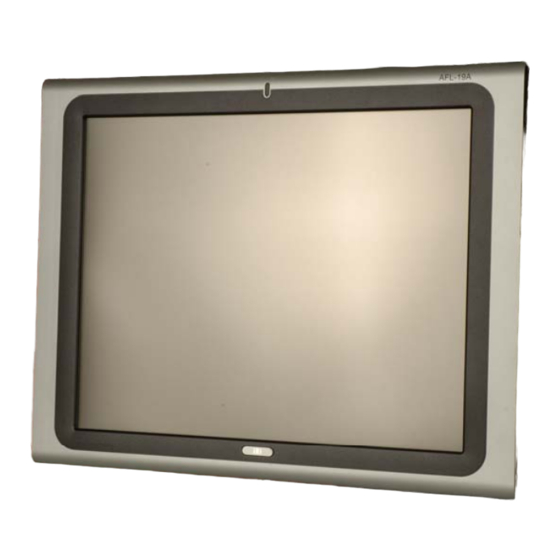
IEI Technology AFOLUX 915A Series User Manual (155 pages)
iEi AFOLUX 915A Series Fanless Touch Panel PC
Brand:
IEI Technology
| Category:
Touch Panel
| Size: 3 MB
Table of Contents
Table of Contents
7
Packing List
6
1 Introduction
15
General Overview
16
Model Variations
16
Figure 1-1: AFL-915
16
Applications
17
Table 1-1: Model Variations
17
External Overview
18
Front Panel
18
Rear Panel
19
Figure 1-2: Front View
19
Standard Features
18
Figure 1-3: AFL-915 Rear View
19
Bottom Panel
20
Figure 1-4: AFL-915 Series External Peripheral Connectors
20
Internal Overview
20
Figure 1-5: Internal Overview
21
2 Specifications
23
Introduction
24
System Specifications
24
Table 2-1: AFL-915 Series System Specifications
25
Dimensions
26
AFL-15A-915 Dimensions
26
Figure 2-1: AFL-15A-915 Front Dimensions (Units in MM)
26
Figure 2-2: AFL-15A-915 Rear Dimensions (Units in MM)
27
AFL-17A-915 Dimensions
28
Figure 2-3: AFL-17A-915 Front Dimensions (Units in MM)
28
Figure 2-4: AFL-17A-915 Rear Dimensions (Units in MM)
29
AFL-19A-915 Dimensions
30
Figure 2-5: AFL-19A-915 Front Dimensions (Units in MM)
30
Cpu Support
31
Figure 2-6: AFL-19A-915 Rear Dimensions (Units in MM)
31
System Chipset
32
Intel ® 915GM Express Overview
32
Intel ® ICH6M Overview
32
Graphics Support
33
Chrontel CH7308A SDVO / LVDS Support
33
Intel ® 915GM Analog CRT Support
33
Figure 2-7: 200-Pin DDR2 SO-DIMM Sockets
34
Compactflash
35
SATA Hard Drive
35
Figure 2-8: Compactflash® Slot
35
Figure 2-9: SATA Hard Drive Slot
35
Memory
34
Storage
34
Bluetooth Module Specifications
36
Figure 2-10: Bluetooth Module
36
Table 2-2: Bluetooth Module Specifications
37
Ethernet Controller Specifications
38
Figure 2-11: GPRS Module
37
Optional Gprs Module Specifications
37
Table 2-3: GPRS Module Specifications
38
Wireless Lan Module
38
Flat Panel Screen Specifications
39
Figure 2-12: Wireless LAN Module
38
Figure 2-13: Ethernet
38
Table 2-4: TFT LCD Monitor Specifications
40
Touch Screen Specifications
40
Table 2-5: Touch Panel Specifications
41
Motherboard Specifications
42
Figure 2-14: Inverter
41
Inverter
41
Table 2-6: Touch Panel Specifications
42
Oem Options
43
Table 2-7: Motherboard Specifications
43
3 Installation
45
Installation Precautions
46
Preinstalled Components
46
Installation and Configuration Steps
47
Unpacking
47
Packing List
48
Cf Card Installation
49
Figure 3-1: Back Cover Retention Screws
49
Gprs Module Installation
50
Figure 3-2: CF Card Location
50
Figure 3-3: CF Card Location
50
Hdd Installation
51
Figure 3-4: CF Card Location
51
Figure 3-5: Aluminum Back Cover Retention Screws
51
Figure 3-6: AFL-915 Hard Drive Bracket Retention Screws
52
Figure 3-7: Hard Drive Retention Screws
52
Figure 3-8: Hard Drive Retention Screws
53
At/Atx Mode Selection
54
Figure 3-9: Hard Drive Retention Screws
54
AT Power Mode
55
ATX Power Mode
55
Figure 3-10: AT/ATX Switch Location
55
Mounting the System
56
Wall Mounting
56
Figure 3-11: Wall-Mounting Bracket
57
Figure 3-12: Chassis Support Screws
58
Figure 3-13: Secure the Panel PC
59
Panel Mounting
59
Figure 3-14: AFL-15A-915 Cutout Dimensions (Units in MM)
60
Figure 3-15: AFL-17A-915 Cutout Dimensions (Units in MM)
60
Figure 3-16: AFL-19A-915 Cutout Dimensions (Units in MM)
61
Arm Mounting
62
Figure 3-17: Tighten the Panel Mounting Clamp Screws
62
Cabinet and Rack Installation
63
Figure 3-18: Arm Mounting Retention Screw Holes
63
Figure 3-19: the Rack/Cabinet Bracket
64
Figure 3-20: Secure the Rack/Cabinet Bracket (AFL-10A-LX/AFL-12A-LX)
65
Figure 3-21: Install into a Rack/Cabinet
65
Bottom Panel Connectors
66
LAN Connection
66
Figure 3-22: LAN Connection
66
Serial Device Connection
67
Figure 3-23: Serial Device Connector
67
USB Device Connection
68
Figure 3-24: USB Device Connection
68
VGA Monitor Connection
69
Figure 3-25: VGA Connector
69
4 System Maintenance
71
Introduction
72
Motherboard Replacement
72
Internal Aluminum Cover Removal
72
Memory Module Replacement
73
Figure 4-1: AFL-19A-915 Aluminum Back Cover Retention Screws
73
Figure 4-2: SO-DIMM Socket Location
74
Jumper Settings
75
Figure 4-3: DDR2 SO-DIMM Module Installation
75
Touch Panel Type Selection (JP3)
76
Compactflash® Setup (JP5 and JP8)
76
Master/Slave Selection (JP5)
76
Voltage Selection (JP8)
76
Table 4-1: Touch Panel Type Selection
76
Table 4-2: Compactflash® Master/Slave Selection
76
Clear CMOS Jumper (JP9)
77
COM3 RI and Voltage Selection (JP6)
77
LCD Type Selection (JP7)
77
Table 4-3: Compactflash® Voltage Selection
77
Table 4-4: COM3 RI and Voltage Selection
77
Table 4-5: LCD Type Selection
77
COM1 and COM2 RI and Voltage Selection (JP10)
78
COM3 RS-232/422/485 Selection (JP11, JP12 and JP13)
78
Table 4-6: Clear CMOS Jumper Settings
78
Table 4-7: COM1 and COM2 RI and Voltage Settings
78
Table 4-8: COM3 Mode Selection
78
Table 4-9: COM3 Mode Selection
79
Table 4-10: COM3 Mode Selection
79
5 Ami Bios Setup
81
Introduction
82
Starting Setup
82
Using Setup
82
BIOS Menu Bar
83
Getting Help
83
Unable to Reboot after Configuration Changes
83
Table 5-1: BIOS Navigation Keys
83
Main
84
Menu 1: Main
84
System Overview
84
Advanced
85
System Date [XX/XX/XX]
85
System Time [XX:XX:XX]
85
CPU Configuration
86
Menu 2: Advanced
86
IDE Configuration
87
Menu 3: CPU Configuration
87
Menu 4: IDE Configuration
88
ATA/IDE Configurations [Compatible]
88
IDE Master and IDE Slave
89
IDE Master, IDE Slave
89
Legacy IDE Channels [SATA Pri, PATA Sec]
89
Menu 5: IDE Master and IDE Slave Configuration
90
Auto-Detected Drive Parameters
90
Type [Auto]
91
Block (Multi Sector Transfer) [Auto]
92
Lba/Large Mode [Auto]
92
PIO Mode [Auto]
92
DMA Mode [Auto]
93
32Bit Data Transfer [Enabled]
94
Auto]
94
Super IO Configuration
95
Menu 6: Super IO Configuration
95
Serial Port1 Address [3F8/IRQ4]
95
Serial Port2 Address [2F8/IRQ3]
96
Serial Port3 Address [3E8]
96
Serial Port3 IRQ [10]
97
Serial Port3 MODE [RS232]
97
Serial Port4 Address [2E8]
97
Serial Port4 IRQ [10]
97
Hardware Health Configuration
98
Menu 7: Hardware Health Configuration
98
CPU FAN Mode Setting [Full on Mode]
98
Temperature 1 Limit of off [000]
99
Fan 1 Start PWM [070]
100
Temperature 1 Limit of Start [020]
100
Fan 1 PWM Control [100]
101
H/W Health Function [Enabled]
101
Slope PWM 1 [0.5 PWM]
101
Remote Access Configuration
102
Menu 8: Remote Access Configuration [Advanced]
103
Remote Access [Disabled]
103
Base Address, IRQ [2F8H,3]
104
Serial Port Mode [115200 8,N,1]
104
Serial Port Number [COM1]
104
Flow Control [None]
105
Redirection after BIOS POST [Always]
105
Terminal Type [ANSI]
105
VT-UTF8 Combo Key Support [Disabled]
105
Sredir Memory Display Delay [Disabled]
106
USB Configuration
106
Menu 9: USB Configuration
107
USB Devices Enabled
107
USB Functions [Enabled]
107
Legacy USB Support [Enabled]
108
USB 2.0 Controller [Enabled]
108
USB2.0 Controller Mode [Hispeed]
108
Menu 10: Pci/Pnp Configuration
109
DMA Channel# [Available]
110
IRQ# [Available]
110
Pci/Pnp
109
Boot
111
Reserved Memory Size [Disabled]
111
Boot Settings Configuration
112
Menu 11: Boot
112
Menu 12: Boot Settings Configuration
113
Quick Boot [Enabled]
113
Quiet Boot [Disabled]
113
Addon ROM Display Mode [Force BIOS]
114
Boot from LAN Function [Disabled]
114
Bootup Num-Lock [On]
114
Boot Device Priority
115
Menu 13: Boot Device Priority Settings
115
Hard Disk Drives
116
Menu 14: Hard Disk Drives
117
Security
117
Menu 15: Security
118
Change Supervisor Password
118
Change User Password
118
Chipset
119
Clear User Password
119
Menu 16: Chipset
119
Northbridge Configuration
120
Menu 17:Northbridge Chipset Configuration
120
Memory Hole [Disabled]
120
Aperture Size Select/Graphic Win Size [256MB]
121
Boot Display Device [Auto]
121
Internal Graphics Mode Select [Enable, 256MB]
121
Southbridge Configuration
122
Menu 18:Southbridge Chipset Configuration
122
Onboard AC'97 [Enabled]
122
Power
123
Onboard BCM5787 Port 1 [Enabled]
123
Onboard BCM5787 Port 2 [Enabled]
123
Onboard Mini-PCIE Slot [Enabled]
123
Advanced Power Configuration
124
Menu 19:Power
124
Power Supply Type [ATX]
124
Menu 20:Power
125
Power Button Mode [On/Off]
125
Restore on AC Power Loss [Last State]
125
PME Resume [Disabled]
126
RTC Resume [Disabled]
126
Exit
127
RI Resume [Disabled]
127
Menu 21:Exit
127
Discard Changes
128
Discard Changes and Exit
128
Load Optimal Defaults
128
Save Changes and Exit
128
Asafety Precautions
129
Safety Precautions
130
General Safety Precautions
130
Anti-Static Precautions
131
Maintenance and Cleaning Precautions
131
Maintenance and Cleaning
131
Cleaning Tools
132
Bbios Configuration Options
133
Bios Configuration Options
133
B.1 BIOS Configuration Options
134
O Ptions
134
Csoftware Drivers
139
Remote Management Tool
140
Touch Panel Driver
140
Introduction
140
Driver Installation
141
Touch Panel Driver Configuration
144
Dwatchdog Timer
145
Example Program
147
Ehazardous Materials Disclosure
149
Hazardous Material Disclosure Table for IPB Products Certified as Rohs Compliant under 2002/95/EC Without Mercury
150
Advertisement
Advertisement
Related Products
IEI Technology AFOLUX AFL-ATOM Series
IEI Technology AFOLUX AM2 Series
IEI Technology AFOLUX 915B Series
IEI Technology AFOLUX CX Series
IEI Technology Afolux LX Series
IEI Technology AFOLUX M Series
IEI Technology 210UPC-V312
IEI Technology ACT-408A-N270
IEI Technology ACT-412A-N270
IEI Technology ACT-457A
IEI Technology Categories
Motherboard
Touch Panel
Computer Hardware
Single board computers
Desktop
More IEI Technology Manuals
Login
Sign In
OR
Sign in with Facebook
Sign in with Google
Upload manual
Upload from disk
Upload from URL