Sign In
Upload
Manuals
Brands
IEI Technology Manuals
Desktop
Afolux LX Series
IEI Technology Afolux LX Series Manuals
Manuals and User Guides for IEI Technology Afolux LX Series. We have
1
IEI Technology Afolux LX Series manual available for free PDF download: User Manual
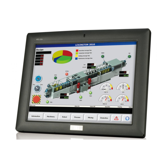
IEI Technology Afolux LX Series User Manual (131 pages)
Fanless All-in-one Panel PC with AMD LX-800 CPU
Brand:
IEI Technology
| Category:
Desktop
| Size: 5 MB
Table of Contents
Table of Contents
7
Manual Conventions
4
1 Introduction
15
Afolux Lx Series Flat Panel Pc Overview
16
Model Variations
16
Table 1-1: Model Variations
16
Applications
17
Standard Features
17
External Overview
18
General Description
18
Front Panel
18
Figure 1-1: Front View
18
Figure 1-2: AFL-07A-LX/AFL-08A-LX Rear View
19
Figure 1-3: AFL-08A-LX Top View
19
Rear Panel
19
Top Panel and Side Panels
19
Bottom Panel
20
Figure 1-4: AFL-08A-LX Side View
20
Figure 1-5: AFOLUX LX Series Bottom View
20
Internal Overview
21
Specifications
21
Preinstalled Hardware Components
21
System Specifications
21
Motherboard Specifications
23
Table 1-2: AFOLUX LX Series System Specifications
23
Table 1-3: Motherboard Specifications
23
Flat Panel Screen Specifications
24
Table 1-4: TFT LCD Monitor Specifications
24
Touch Screen Specifications
24
Bluetooth Module Specifications
25
Table 1-5: Touch Panel Specifications
25
Optional GPRS Module Specifications
26
Table 1-6: Bluetooth Module Specifications
26
Table 1-7: GPRS Module Specifications
26
Dimensions
27
AFL-07A-LX Dimensions
27
Figure 1-6: AFL-07A-LX Dimensions (Units in MM)
27
AFL-08A-LX Dimensions
28
Figure 1-7: AFL-08A-LX Dimensions (Units in MM)
28
AFL-10A-LX Dimensions
29
Figure 1-8: AFL-10A-LX Dimensions (Units in MM)
29
AFL-12A-LX Dimensions
30
Figure 1-9: AFL-12A-LX Dimensions (Units in MM)
30
2 Motherboard
31
Introduction
32
Cpu Support
32
AMD Geode™ LX 800 500Mhz Specifications
32
AMD Geode™ LX 800 500Mhz Power Management
33
System Chipset
33
Graphics Support
34
Table 2-1: Geode LX Graphics Features
34
Ethernet Controller Specifications
36
Overview
36
Features
36
Peripheral Device Interfaces, Connectors, and Slots
37
OEM Options
37
Internal Slots
37
Internal Peripheral Device Connectors
37
External Peripheral Device Connectors
38
Figure 2-1: AFLMB-LX800 Connector Overview
38
3 Installation
39
Installation Precautions
40
Preinstalled Components
40
Installation and Configuration Steps
41
Unpacking
41
Packing List
42
Cf Card Installation
43
Figure 3-1: Back Cover Retention Screws
43
Figure 3-2: AFL-08A-LX Plastic Back Cover Removal
44
Figure 3-3: CF Card Location
44
Figure 3-4: AFL-08A-LX Plastic Back Cover Replacement
44
HDD Installation (AF-12A-LX Only)
45
Figure 3-5: AFL-12A-LX Aluminum Back Cover Retention Screws
45
Figure 3-6: Four Hexagonal Pillars on the Bottom Panel
45
Figure 3-7: AFL-12A-LX HDD Bracket Retention Screws
46
Figure 3-8: AF-12A-LX HDD Retention Screws
46
At/Atx Mode Selection
47
AT Power Mode
47
Figure 3-9: AT/ATX Switch Location
47
ATX Power Mode
48
Mounting the System
48
Wall Mounting
48
Figure 3-10: Wall-Mounting Bracket
49
Figure 3-11: Chassis Support Screws
50
Figure 3-12: Secure the Panel PC
51
Panel Mounting
51
Figure 3-13: AFL-07A-LX Panel Opening
52
Figure 3-14: AFL-08A-LX Panel Opening
52
Figure 3-15: AFL-10A-LX Panel Opening
52
Figure 3-16: AFL-12A-LX Panel Opening
53
Arm Mounting
54
Figure 3-17: Tighten the Panel Mounting Clamp Screws (AFL-10A/12A-LX)
54
Figure 3-19: AFL-10A-LX/AFL-12A-LX Arm Mounting Retention Screw Holes
55
Cabinet and Rack Installation
56
Figure 3-18: AFL-07A-LX/AFL-08A-LX Arm Mounting Retention Screw Holes
55
Figure 3-20: the Rack/Cabinet Bracket
56
Figure 3-21: Secure the Rack/Cabinet Bracket (AFL-10A-LX/AFL-12A-LX)
57
Bottom Panel Connectors
58
LAN Connection
58
Figure 3-22: Install into a Rack/Cabinet
58
Serial Device Connection
59
Figure 3-23: LAN Connection
59
Figure 3-24: Serial Device Connector
60
USB Device Connection
61
Figure 3-25: USB Device Connection
61
4 System Maintenance
63
System Maintenance Introduction
64
Motherboard Replacement
64
Internal Aluminum Cover Removal
64
AFL-07A-LX Internal Aluminum Cover Removal
65
Figure 4-1: AFL-07A-LX Aluminum Back Cover Retention Screws
65
Figure 4-2: Four Hexagonal Pillars on the Bottom Panel (AFL-07A-LX)
65
AFL-08A-LX Internal Aluminum Cover Removal
66
Figure 4-3: AFL-08A-LX Aluminum Back Cover Retention Screws
66
Figure 4-4: Four Hexagonal Pillars on the Bottom Panel (AFL-08A-LX)
66
Figure 4-5: Wireless Module Cables
67
Figure 4-6: the Internal Aluminum Cover Removal
67
AFL-10A-LX Internal Aluminum Cover Removal
68
Figure 4-7: Power Switch Cable
68
Figure 4-8: AFL-10A-LX Aluminum Back Cover Retention Screws
68
Figure 4-9: Four Hexagonal Pillars on the Bottom Panel (AFL-10A-LX)
68
AFL-12A-LX Internal Aluminum Cover Removal
69
Figure 4-8: AFL-12A-LX Aluminum Back Cover Retention Screws
69
Figure 4-9: Four Hexagonal Pillars on the Bottom Panel (AFL-12A-LX)
69
Figure 4-10: SO-DIMM Socket Location
70
Memory Module Replacement
70
Figure 4-11: DDR SO-DIMM Module Installation
71
JP3: COM3 Pin-9 Signal Select Jumper Settings
72
Table 4-1: COM3 Pin-9 Signal Select Jumper Settings
72
JP4: COM1 and COM2 Pin-9 Signal Select Jumper Settings
73
JP5: COM2 Mode Select Jumper Settings
73
Figure 4-12: Jumper Locations
72
Table 4-2: COM1 and COM2 Pin-9 Signal Select Jumper Settings
73
Table 4-3: COM2 Mode Select Jumper Settings
73
JP6: COM2 Mode Select Jumper Settings
74
Table 4-4: COM2 Mode Select Jumper Settings
74
Jumper Settings
71
5 Award Bios Setup
75
Introduction
76
Starting Setup
76
Using Setup
76
Getting Help
77
Main BIOS Menu
77
Table 5-1: BIOS Navigation Keys
77
BIOS Menu 1: Award BIOS CMOS Setup Utility
77
Load Fail-Safe Defaults
78
Load Optimized Defaults
78
Set Supervisor Password
78
Standard Cmos Features
79
Set User Password
79
Save & Exit Setup
79
Exit Without Saving
79
BIOS Menu 2: Standard CMOS Features
80
Date [Day MM:DD:yyyy]
80
Time [Hh/MM/Ss]
80
IDE Master and IDE Slave
80
Halt on [All, but Keyboard]
81
Base Memory
81
Extended Memory
81
Total Memory
81
IDE Primary Master/Slave
82
IDE HDD Auto-Detection [Press Enter]
82
IDE Primary Master [Auto]
82
Access Mode [Auto]
82
Advanced Bios Features
84
BIOS Menu 3: Advanced BIOS Features
84
Virus Warning [Disabled]
85
CPU Internal Cache [Enabled]
85
Boot from LAN Control [Disabled]
85
Boot Device
86
Boot Other Device [Enabled]
87
Boot up Numlock Status [On]
87
Gate A20 Option [Fast]
87
Typematic Rate Setting [Disabled]
87
Typematic Rate (Chars/Sec) [6]
88
Typematic Delay (Msec) [250]
88
Security Option [Setup]
89
OS Select for DRAM > 64MB [Non-OS2]
89
Small Logo (EPA) Show [Disabled]
89
Advanced Chipset Features
90
BIOS Menu 4: Advanced Chipset Features
90
CPU Frequency [500Mhz]
90
Memory Frequency [Auto]
91
Video Memory Size [32M]
91
Onboard Audio [Enabled]
91
BIOS Menu 6: Integrated Peripherals
92
On-Chip IDE Channel 1 [Enabled]
92
Drive PIO Mode [Auto]
93
IDE UDMA [Auto]
93
IDE DMA Transfer Access [Enabled]
93
IDE HDD Block Mode [Enabled]
94
Onboard Serial Port 1 [3F8/IRQ4]
94
Onboard Serial Port 2 [2F8/IRQ3]
94
Integrated Peripherals
92
Power Management Setup
95
Touch Controller Port [2E8]
95
Touch Controller Use IRQ [IRQ7]
95
BIOS Menu 7: Power Management Setup
96
ACPI Function [Enabled]
96
ACPI Suspend Type [S1(POS)]
97
Power Management [ACPI]
97
Standby Mode [Disabled]
97
Suspend Mode [Disabled]
98
Modem Use of IRQ
99
Wake-On Lan Control [Disabled]
99
Soft-Off by PWR-BTTN [Instant-Off]
99
Power-On by Alarm [Disabled]
100
Time (Hh:MM:ss) Alarm
100
IRQ Wakeup Events [Press Enter]
100
BIOS Menu 8: IRQ Wakeup Events
101
BIOS Menu 9: Pnp/Pci Configurations
102
PNP os Installed [No]
102
Init Display First [Onboard]
103
Reset Configuration Data [Disabled]
103
Resources Controlled by [Auto (ESCD)]
103
IRQ Resources [Press Enter]
103
Memory Resources [Press Enter]
104
PCI/VGA Palette Snoop [Disabled]
104
Pnp/Pci Configurations
102
BIOS Menu 10: PC Health Status
105
Pc Health Status
105
Asafety Precautions
107
Safety Precautions
108
General Safety Precautions
108
Anti-Static Precautions
109
Maintenance and Cleaning Precautions
109
Maintenance and Cleaning
109
Cleaning Tools
110
Bbios Configuration Options
111
Bios Configuration Options
111
B.1 BIOS Configuration Options
112
Csoftware Drivers
115
Remote Management Tool
116
Touch Panel Driver
116
Introduction
116
Driver Installation
117
Touch Panel Driver Configuration
120
Dwatchdog Timer
121
Example Program
123
Ehazardous Materials Disclosure
125
Hazardous Material Disclosure Table for IPB Products Certified as Rohs Compliant under 2002/95/EC Without Mercury
126
Findex
129
Advertisement
Advertisement
Related Products
IEI Technology AFOLUX CX Series
IEi Technology AFL2-12A-HM65 Series
IEI Technology AFL-W19A
IEI Technology AFL-W19B
IEI Technology AFL-42A-9652
IEI Technology AFL2-W15A-N270/L325
IEI Technology AFL3-12A/W15A-BT
IEI Technology AFL3-12A-BT
IEI Technology AFL3-08A-BT
IEI Technology Afolux Monitor
IEI Technology Categories
Motherboard
Touch Panel
Computer Hardware
Single board computers
Desktop
More IEI Technology Manuals
Login
Sign In
OR
Sign in with Facebook
Sign in with Google
Upload manual
Upload from disk
Upload from URL