Sign In
Upload
Manuals
Brands
IEI Technology Manuals
Monitor
AFOLUX M Series
IEI Technology AFOLUX M Series Manuals
Manuals and User Guides for IEI Technology AFOLUX M Series. We have
1
IEI Technology AFOLUX M Series manual available for free PDF download: User Manual
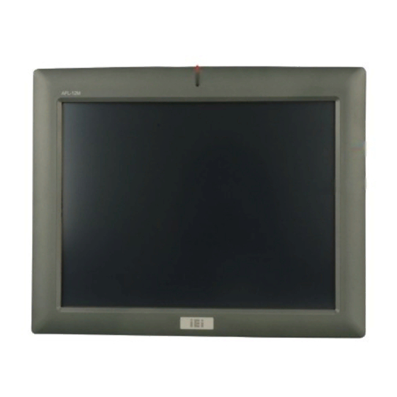
IEI Technology AFOLUX M Series User Manual (196 pages)
7"~19" Multimedia Touch Monitor with Built-in Speakers, VGA, Component, Composite, S-Video and DVI-D Input IP 64 Protection
Brand:
IEI Technology
| Category:
Monitor
| Size: 8 MB
Table of Contents
User Manual
1
Packing List
6
Table of Contents
7
List of Figures
13
Introduction
21
Afl M Series Lcd Monitor Overview
23
Added Features
23
Standard Features
23
IEI Smartosd
24
Model Variations
24
External Overview
25
Front View
25
Table 1-1: AFL Series Model Variants
25
Rear View
26
Figure 1-1: AFL-12M Front View
26
Figure 1-2: AFL-15M Front View
26
Series Specifications
27
Figure 1-3: AFL-12M Rear View
27
Certifications
28
Table 1-2: AFL M Series Specifications
28
Mechanical Overview
29
Introduction
30
Front View
30
Figure 2-1: AFL-12M Front View
30
Figure 2-2: AFL-15M Front View
31
Bottom Panel
32
AFL-07M/08MH/10M/12M Connectors
32
AFL-15M/17M/19M Connectors
32
Physical Dimensions
33
General Physical Dimensions
33
Figure 2-3: AFL-12M Bottom Panel View
33
Figure 2-4: AFL-15M Bottom Panel View
33
Table 2-1: General Physical Dimensions
34
AFL-07M Physical Dimensions
35
Figure 2-5: AFL-07M Physical Dimensions (Millimeters)
35
AFL-08MH Physical Dimensions
36
Figure 2-6: AFL-08MH Physical Dimensions (Millimeters)
36
AFL-10M Physical Dimensions
37
Figure 2-7: AFL-10M Physical Dimensions (Millimeters)
37
AFL-12M Physical Dimensions
38
Figure 2-8: AFL-12M Physical Dimensions (Millimeters)
38
AFL-15M Physical Dimensions
39
Figure 2-9: AFL-15M Physical Dimensions (Millimeters)
39
AFL-17M Physical Dimensions
40
Figure 2-10: AFL-17M Physical Dimensions (Millimeters)
40
AFL-19M Physical Dimensions
41
Figure 2-11: AFL-19M Physical Dimensions (Millimeters)
41
Mounting Kits
42
Mounting Options
42
Panel Mounting
42
Table 2-2: AFL Series Mounting Kits
42
Rack and Cabinet Mounting
43
Table 2-3: Panel Mounting Clamps
43
Table 2-4: Rack Mounting Holes
43
Figure 2-12: Typical Wall Mounting
44
Specifications
45
Lcd Specifications
46
Table 3-1: AFL-07M LCD Specifications
47
Table 3-2: AFL-08MH LCD Specifications
48
Table 3-3: AFL-10M LCD Specifications
48
Table 3-4: AFL-12M LCD Specifications
49
Table 3-5: AFL-15M LCD Specifications
50
Table 3-6: AFL-17M LCD Specifications
51
Table 3-7: AFL-19M LCD Specifications
52
Table 3-8: Touch Panel Models
53
Table 3-9: Touch Panel Dimensions (MM)
54
Table 3-10: Touch Panel Specifications
55
Table 3-11: Touch Panel RS-232 Controller Specifications
56
Table 3-12: Touch Panel USB Controller Specifications
57
Table 3-13: Power Adapter Specifications
58
Power Adapters
58
Figure 4-1: AV-9962 AD Board Overview
60
Figure 4-2: AV-9962 Connector and Jumper Locations
62
Table 4-1: AV-9962 Peripheral Interface Connectors
63
Table 4-2: AV-9962 Rear Panel Connectors
63
T Able 4-3: AV-9962 On-Board Jumpers
63
Table 4-4: Audio Output Connector Pinouts
64
Figure 4-3: Audio Output Connector Location
65
Table 4-5: Auto-Dimming Connector Pinouts
65
Figure 4-4: Auto-Dimming Connector Location
66
Table 4-6: Debug Port Connector Pinouts
66
Figure 4-5: Debug Port Connector Location
67
Figure 4-6: OSD and LED Connector Location
68
Table 4-7: OSD and LED Connector Pinouts
68
Table 4-8: LED and Remote Sensor Connector Pinouts
68
Figure 4-7: LED and Remote Sensor Connector Location
69
Table 4-9: Backlight Inverter Connector Pinouts
69
Figure 4-8: Backlight Inverter Connector Location
70
Table 4-10: IR Sensor Connector Pinouts
70
Figure 4-9: IR Sensor Connector Location
71
Figure 4-10: LVDS Signal Output Connector Location
72
Table 4-11: LVDS Signal Output Connector Pinouts
72
Table 4-12: Power Output Connector Pinouts (CN15)
72
Figure 4-11: Power Output Connector Locations
73
Table 4-13: Remote Control Connector Pinouts
73
Figure 4-12: Remote Control Connector Location
74
Figure 4-13: TTL Signal Output Connector Location
75
Table 4-14: TTL Signal Output Connector Pinouts
75
Figure 4-14: Touch Panel Connector Location
76
Table 4-15: Touch Panel Connector Pinouts
76
Figure 4-15: Jumpers
77
Figure 4-16: AV-9962 Jumper Locations
77
Table 4-16: LCD Panel Voltage Select Jumper Settings
78
Table 4-17: LCD Panel Power Input Jumper Settings
78
Figure 4-17: AV-9962 External (Rear Panel) Connectors
79
Figure 4-18: Component Video Connector Pinout Locations
80
Table 4-18: Audio Jack Pinouts
80
Table 4-19: Component Video Connector Pinouts
80
Table 4-20: Composite Signal Input BNC Connector (J7) Pinouts
81
Table 4-21: Composite Signal Input Connector (J6) Pinouts
81
Table 4-22: DC 12V Connector Pinouts
82
Table 4-23: RS-232 Touch Panel Connector Pinouts
82
Figure 4-19: S-Video Connector Pinout Locations
83
Table 4-24: S-Video Connector Pinouts
83
Table 4-25: USB Touch Panel Connector Pinouts
83
Figure 4-20: USB Touch Panel Connector
84
Figure 4-21: VGA Connector Pinout Locations
84
Table 4-26: VGA Connector Pinouts
84
Figure 4-22: AV-6962 AD Board Overview
85
Figure 4-23: AV-6962 Connector and Jumper Locations
87
Table 4-27: AV-6962 Peripheral Interface Connectors
88
Table 4-28: AV-6962 Rear Panel Connectors
89
Table 4-29: AV-6962 On-Board Jumpers
89
Figure 4-24: Audio Output Connector Location
90
Table 4-30: Audio Output Connector Pinouts
90
Figure 4-25: Auto-Dimming Connector Location
91
Table 4-31: Auto-Dimming Connector Pinouts
91
Figure 4-26: Debug Port Connector Location
92
Table 4-32: Debug Port Connector Pinouts
92
Figure 4-27: Backlight Inverter Connector Location
93
Table 4-33: Backlight Inverter Connector Pinouts
93
Table 4-34: IR Sensor Connector Pinouts
93
Figure 4-28: IR Sensor Connector Location
94
Figure 4-29: LVDS Signal Output Connector Location
95
Table 4-35: LVDS Signal Output Connector Pinouts
95
Figure 4-30: OSD and LED Connector Location
96
Table 4-36: OSD and LED Connector Pinouts
96
Figure 4-31: Power Output Connector Locations
97
Table 4-37: Power Output Connector Pinouts (CN15)
97
Table 4-38: Power Input Connector Pinouts (CN15)
97
Figure 4-32: Power Input Connector Locations
98
Table 4-39: Remote Control Connector Pinouts
98
Figure 4-33: Remote Control Connector Location
99
Table 4-40: RS-232 Serial Port Connector Pinouts
99
Figure 4-34: RS-232 Serial Port Connector Location
100
Table 4-41: USB Connector Pinouts
100
Figure 4-35: USB Connector Location
101
Figure 4-36: Jumpers
101
Figure 4-37: Jumper Locations
102
Table 4-42: LCD Panel Voltage Select Jumper Settings
102
Figure 4-38: AV-6962 External (Bottom Panel) Connectors
103
Figure 4-39: Component Video Connector Pinout Locations
104
Table 4-43: Audio Jack Pinouts
104
Table 4-44: Component Video Connector Pinouts
104
Table 4-45: Composite Signal Input BNC Connector (J10) Pinouts
105
Table 4-46: Composite Signal Input Connector (J9) Pinouts
105
Figure 4-40: DVI-D Connector Pinout Locations
106
Table 4-47: DVI-D Connector Pinouts
106
Table 4-48: DC 12V Connector Pinouts
107
Figure 4-41: S-Video Connector Pinout Locations
108
Table 4-49: RS-232 Touch Panel Connector Pinouts
108
Table 4-50: S-Video Connector Pinouts
108
Figure 4-42: USB Touch Panel Connector
109
Table 4-51: USB Touch Panel Connector Pinouts
109
Figure 4-43: VGA Connector Pinout Locations
110
Table 4-52: VGA Connector Pinouts
110
Table 5-1: External Peripheral Interface Connectors
116
Figure 5-1: VGA Connector
117
Figure 5-2: 12V Power Connector
117
Figure 5-3: DVI Connector
118
Figure 5-4: Optional RS-232 Touch Panel Connector
118
Table 5-2: Optional RS-232 Touch Panel Connector Pinouts
118
Figure 5-5: USB Touch Panel Connector
119
Table 5-3: USB Touch Panel Connector Pinouts
119
Table 5-4: Mounting Kits
120
Figure 5-6: AFL-07M Panel Opening
121
Figure 5-7: AFL-08MH Panel Opening
121
Figure 5-8: AFL-12M Panel Opening
121
Figure 5-9: Insert the Monitor
122
Figure 5-10: Tighten the Panel Mounting Clamp Screws (AFL-12M)
123
Table 5-5: AFL Series VESA Standard
123
Figure 5-11: Wall-Mounting Bracket
124
Figure 5-12: Chassis Support Screws
125
Figure 5-13: Secure the Monitor
126
Figure 5-14: Wall-Mounting Bracket
127
Figure 5-15: Chassis Support Screws
128
Figure 5-16: Monitor Stand Mounting
129
Figure 5-17: AFL-07M/AFL-08MH Arm Mounting Retention Screw Holes
130
Figure 5-18: AFL-10M/12M Arm Mounting Retention Screw Holes
130
Figure 5-19: AFL-15M/17M/19M Arm Mounting Retention Screw Holes
131
Figure 6-1: OSD Control Buttons
133
Osd Menu Structure
134
Table 6-1: OSD Menus
135
Figure 6-2: Image Menu
136
Using the Osd
136
Figure 6-3: Display Menu
137
Figure 6-4: Pip Menu
138
Figure 6-5: Color Menu
139
Figure 6-6: System Menu
140
Figure 6-7: OSD Configuration
141
Figure 6-8: Auto Brightness Configuration
142
Figure 6-9: Remote Control
143
Software Drivers
144
Figure 7-1: Setup Icon
147
Figure 7-2: Welcome Screen
147
Figure 7-3: License Agreement
148
Figure 7-4: Initiate Install
148
Figure 7-5: Installation Starts
148
Figure 7-6: Finish Installation
149
Figure 7-7: Control Panel
150
Figure 7-8: Remove Touch Screen Driver
150
Figure 7-9: Driver CD Pop up Screen
152
Figure 7-10: Install Shield Wizard Preparation
153
Figure 7-11: Welcome Screen
153
Figure 7-12: Install PS/2 Interface Driver
154
Figure 7-13: Install PS/2 Interface Driver
155
Figure 7-14: Touch Monitor/Usb Touch Controller Confirmation
155
Figure 7-15: Controller Installation Directory
156
Calibrating the Touch Screen
158
Gasket Replacement
162
Safety Precautions
165
General Safety Precautions
166
Anti-Static Precautions
167
Maintenance and Cleaning Precautions
167
Maintenance and Cleaning
167
Cleaning Tools
168
B Certifications
169
Rohs Compliant
170
Ip 64 Compliant Front Panel
170
C Auto-Dimming
171
Auto-Dimming Configurations
172
Default Settings
172
OSD Control
173
D Smartosd
174
IEI Smartosd Quick Installation Guide
175
Pre-Installation Notice
175
Software Illustration
175
EDID Page
177
Image Page
178
Display Page (for Analog Signal)
179
Color Page
180
PIP Page (for MDM/AFLUX Series)
181
System Page
182
User Page
183
About Page
184
Install Software
184
Smartosd FAQ
190
E Hazardous Materials Disclosure
193
Hazardous Material Disclosure Table for IPB Products Certified as Rohs Compliant under 2002/95/EC Without Mercury
194
Advertisement
Advertisement
Related Products
IEI Technology Afolux Monitor
IEI Technology AFL M Series
IEI Technology AFOLUX CX Series
IEI Technology Afolux LX Series
IEI Technology AFOLUX AFL-ATOM Series
IEI Technology AFOKAR-08A-RK39
IEI Technology AFOKAR-08A
IEI Technology AFL-A-N270
IEI Technology AFL4-W101-ADLP-i3/8G
IEI Technology AFL4-W121-ADLP-i7/8G
IEI Technology Categories
Motherboard
Touch Panel
Computer Hardware
Single board computers
Desktop
More IEI Technology Manuals
Login
Sign In
OR
Sign in with Facebook
Sign in with Google
Upload manual
Upload from disk
Upload from URL