Sign In
Upload
Manuals
Brands
IEI Technology Manuals
Desktop
AFOLUX CX Series
IEI Technology AFOLUX CX Series Manuals
Manuals and User Guides for IEI Technology AFOLUX CX Series. We have
1
IEI Technology AFOLUX CX Series manual available for free PDF download: User Manual
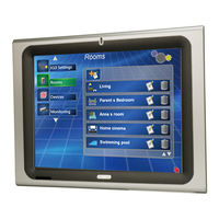
IEI Technology AFOLUX CX Series User Manual (155 pages)
Fanless All-in-one Panel PC with VIA C7/Eden CPU TFT LCD, Wireless LAN, Bluetooth, Touch Screen RoSH Compliant, IP 64 Protection
Brand:
IEI Technology
| Category:
Desktop
| Size: 6 MB
Table of Contents
Table of Contents
7
Manual Conventions
4
Packing List
6
List of Figures
11
1 Introduction
15
Afolux CX Series Flat Panel Pc Overview
16
Model Variations
16
Table 1-1: Model Variations
16
Applications
17
Standard Features
17
External Overview
18
Front Panel
18
General Description
18
Figure 1-1: Front View
18
Figure 1-2: AFL-10A-CX/AFL-12B-CX Series Rear View
19
Figure 1-3: AFL-15A-CX/AFL-17A-CX/AFL-19A-CX Series Rear View
19
Rear Panel
19
Bottom Panel
20
Afl-10A-CX/Afl-12B-CX
20
Afl-15A-CX/Afl-17A-CX/Afl-19A-CX
20
Figure 1-4: AFL-10A-CX/AFL-12B-CX Bottom View
20
Figure 1-5: AFOLUX CX Series Bottom View
21
Internal Overview
21
Specifications
22
Preinstalled Hardware Components
22
Figure 1-6: AFOLUX CX Series Internal Overview
22
System Specifications
23
Table 1-2: AFOLUX CX Series System Specifications
24
Motherboard Specifications
25
Table 1-3: Motherboard Specifications
25
Flat Panel Screen Specifications
26
Afl-10A-CX/Afl-12B-CX
26
Afl-15A-CX/Afl-17A-CX/Afl-19A-CX
26
Table 1-4: AFL-10A/12B-CX TFT LCD Monitor Specifications
26
Table 1-5: AFL-15A/17A/19A-CX TFT LCD Monitor Specifications
27
Table 1-6: Touch Panel Specifications
28
Touch Screen Specifications
28
Bluetooth Module Specifications
29
Table 1-7: Bluetooth Module Specifications
29
Optional GPRS Module Specifications
30
Table 1-8: GPRS Module Specifications
30
Dimensions
31
AFL-10A-CX Dimensions
31
Figure 1-7: AFL-10A-CX Dimensions (Units in MM)
31
AFL-12B-CX Dimensions
32
Figure 1-8: AFL-12B-CX Dimensions (Units in MM)
32
AFL-15A-CX Dimensions
33
Figure 1-9: AFL-15A-CX Dimensions (Units in MM)
33
AFL-17A-CX Dimensions
34
Figure 1-10: AFL-17A-CX Dimensions (Units in MM)
34
AFL-19A-CX Dimensions
35
Figure 1-11: AFL-19A-CX Dimensions (Units in MM)
35
2 Motherboard
37
Introduction
38
Cpu Support
38
VIA C7 Specifications
38
System Chipset
39
Graphics Support
39
Ethernet Controller Specifications
40
Features
40
Overview
40
Peripheral Device Interfaces, Connectors, and Slots
41
Internal Peripheral Device Connectors
41
Internal Slots
41
OEM Options
41
External Peripheral Device Connectors
42
Figure 2-1: AFLMB-CX700 Connector Overview
42
3 Installation
43
Installation Precautions
44
Preinstalled Components
44
Installation and Configuration Steps
45
Unpacking
45
Packing List
46
Cf Card Installation
47
Figure 3-1: AFL-10A-CX Back Cover Retention Screws
48
Figure 3-2: AFL-12B-CX Back Cover Retention Screws
48
Figure 3-3: AFL-15A-CX Back Cover Retention Screws
48
Figure 3-4: AFL-17A-CX Back Cover Retention Screws
49
Figure 3-5: AFL-19A-CX Back Cover Retention Screws
49
Hdd Installation
50
Figure 3-6: CF Card Location
50
Figure 3-7: AFL-12B-CX Aluminum Back Cover Retention Screws
50
Figure 3-8: AFL-15A-CX Aluminum Back Cover Retention Screws
51
Figure 3-9: AFL-17A-CX Aluminum Back Cover Retention Screws
51
Figure 3-10: AFL-19A-CX Aluminum Back Cover Retention Screws
52
Figure 3-11: AFL-19A-CX HDD Bracket Retention Screws
52
At/Atx Mode Selection
53
Figure 3-12: AFL-CX HDD Retention Screws
53
AT Power Mode
54
Figure 3-13: AT/ATX Switch Location (AFL-10A-CX/AFL-12B-CX)
54
Figure 3-14: AT/ATX Switch Location (AFL-15A-CX/AFL-17A-CX/AFL-19A-CX)
54
ATX Power Mode
55
Mounting the System
55
Wall Mounting
55
Figure 3-15: Wall-Mounting Bracket
56
Figure 3-16: Chassis Support Screws
57
Arm Mounting
58
Figure 3-17: Secure the Panel PC
58
Figure 3-18: Arm Mounting Retention Screw Holes (AFL-10A-CX/AFL-12B-CX)
59
Figure 3-19: Arm Mounting Retention Screw Holes (AFL-15A/17A/19A-CX)
60
Panel Mounting (AFL-10A-CX/AFL-12B-CX Only)
60
Figure 3-20: AFL-10A-CX Panel Opening
61
Figure 3-21: AFL-12B-CX Panel Opening
61
Cabinet and Rack Installation (AFL-10A-CX/AFL-12B-CX Only)
62
Figure 3-22: Tighten the Panel Mounting Clamp Screws (AFL-10A/12B-CX)
62
Figure 3-23: the Rack/Cabinet Bracket
63
Figure 3-24: Secure the Rack/Cabinet Bracket (AFL-10A/12B-CX)
63
Bottom Panel Connectors
64
LAN Connection
64
Figure 3-25: Install into a Rack/Cabinet
64
Figure 3-26: LAN Connection
65
Serial Device Connection
66
Figure 3-27: Serial Device Connector
66
USB Device Connection
67
Figure 3-28: USB Device Connection
67
4 System Maintenance
69
System Maintenance Introduction
70
Motherboard Replacement
70
Internal Aluminum Cover Removal
70
Figure 4-1: AFL-10A-CX Aluminum Back Cover Retention Screws
71
Figure 4-2: AFL-12B-CX Aluminum Back Cover Retention Screws
71
Figure 4-3: AFL-15A-CX Aluminum Back Cover Retention Screws
72
Figure 4-4: AFL-17A-CX Aluminum Back Cover Retention Screws
72
Memory Module Replacement
73
Figure 4-5: AFL-19A-CX Aluminum Back Cover Retention Screws
73
Figure 4-6: SO-DIMM Socket Location
74
Jumper Settings
75
Figure 4-7: DDR2 SO-DIMM Module Installation
75
J4: LCD Voltage Select Jumper Settings
76
Table 4-1: LCD Voltage Setup Jumper Settings
76
JP7: COM2 Mode Select Jumper Settings
77
JP8: COM2 Mode Select Jumper Settings
77
Figure 4-8: Jumper Locations
76
Table 4-2: COM2 Mode Select Jumper Settings
77
Table 4-3: COM2 Mode Select Jumper Settings
77
5 Ami Bios Setup
79
Introduction
80
Starting Setup
80
Using Setup
80
BIOS Menu Bar
81
Getting Help
81
Unable to Reboot after Configuration Changes
81
Table 5-1: BIOS Navigation Keys
81
Main
82
Menu 1: Main
82
System Overview
82
Advanced
83
System Date [XX/XX/XX]
83
System Time [XX:XX:XX]
83
CPU Configuration
84
IDE Configuration
85
Menu 3: CPU Configuration
85
Menu 4: IDE Configuration
86
IDE Master and IDE Slave
86
IDE Master, IDE Slave
87
Menu 5: IDE Master and IDE Slave Configuration
87
Auto-Detected Drive Parameters
87
Type [Auto]
88
Zip
88
Block (Multi Sector Transfer) [Auto]
89
Lba/Large Mode [Auto]
89
PIO Mode [Auto]
89
DMA Mode [Auto]
90
32Bit Data Transfer [Enabled]
91
Auto]
91
Super IO Configuration
92
Menu 6: Super IO Configuration
92
Serial Port1 Address [3F8]
92
Serial Port1 IRQ [4]
93
Serial Port2 Address [2F8]
93
Serial Port2 IRQ [3]
93
Serial Port3 Address [3E8]
93
Serial Port3 IRQ [11]
94
Serial Port4 Address [2E8]
94
Serial Port4 IRQ [10]
94
ACPI Configuration
95
Menu 7: ACPI Configuration
95
Suspend Mode [S1(POS)]
95
APM Configuration
96
Menu 8:Advanced Power Management Configuration
96
AT/ATX Power [ATX]
96
Power Button Mode [On/Off]
96
Restore on AC Power Loss [Power Off]
97
Resume on Lan/Ring [Disabled]
97
Resume on PME# [Disabled]
97
Remote Access Configuration
98
Resume on RTC Alarm [Disabled]
98
RTC Alarm Date (Days)
98
System Time
98
Menu 9: Remote Access Configuration [Advanced]
99
Flow Control
99
Redirection after BIOS POST
99
Remote Access [Enabled]
99
Serial Port Mode
99
Serial Port Number
99
Base Address, IRQ [3F8H,4]
100
Serial Port Mode [115200 8,N,1]
100
Serial Port Number [COM1]
100
Terminal Type
100
VT-UTF8 Combo Key Support
100
Redirection after BIOS POST [Always]
101
Terminal Type [ANSI]
101
USB Configuration
101
Menu 10: USB Configuration
102
USB 1.1 Ports Configuration [USB 6 Ports]
102
USB Devices Enabled
102
Legacy USB Support [Enabled]
103
USB 2.0 Ports Enable [Enabled]
103
USB Mass Storage Device Configuration
103
USB2.0 Controller Mode [Hispeed]
103
Menu 11: USB Mass Storage Device Configuration
104
USB Mass Storage Reset Delay [20 Sec]
104
Device
105
Emulation Type [Auto]
105
Pci/Pnp
106
Menu 12: Pci/Pnp Configuration
107
IRQ# [Available]
107
DMA Channel# [Available]
108
Reserved Memory Size [Disabled]
108
Boot
109
Boot Settings Configuration
109
Menu 14: Boot Settings Configuration
110
Quick Boot [Enabled]
110
Quiet Boot [Disabled]
110
Addon ROM Display Mode [Force BIOS]
111
Bootup Num-Lock [On]
111
PXE Remote Boot [Disabled]
111
Boot Device Priority
112
On Board Lan Function [Lan1+Lan2]
112
Spread Spectrum Function [Enabled]
112
Hard Disk Drives
113
Menu 15: Boot Device Priority Settings
113
Removable Drives
114
Menu 16: Hard Disk Drives
114
Menu 17: Removable Drives
115
Change Supervisor Password
116
Change User Password
116
Security
115
Chipset
117
VGA Frame Buffer Size [64MB]
117
Display Device Select [CRT+LCD]
118
High Definition Audio [Auto]
118
Panel Type
118
Serial ATA IDE Controller
118
Exit
119
Discard Changes and Exit
119
Save Changes and Exit
119
Discard Changes
120
Load Failsafe Defaults
120
Load Optimal Defaults
120
Ainterface Connectors
121
Peripheral Interface Connectors
122
Bsafety Precautions
129
Safety Precautions
130
General Safety Precautions
130
Anti-Static Precautions
131
Maintenance and Cleaning Precautions
131
Maintenance and Cleaning
131
Cleaning Tools
132
Cbios Configuration Options
133
Bios Configuration Options
133
C.1 BIOS Configuration Options
134
Dsoftware Drivers
139
Remote Management Tool
140
Touch Panel Driver
140
D.1 R Emote M Anagement T Ool
140
Introduction
140
Driver Installation
141
Touch Panel Driver Configuration
144
Ewatchdog Timer
145
Example Program
147
Fhazardous Materials Disclosure
149
Hazardous Material Disclosure Table for IPB Products Certified as Rohs Compliant under 2002/95/EC Without Mercury
150
Gindex
153
Advertisement
Advertisement
Related Products
IEI Technology Afolux LX Series
IEi Technology AFL2-12A-HM65 Series
IEI Technology AFL-W19A
IEI Technology AFL-W19B
IEI Technology AFL-42A-9652
IEI Technology AFL2-W15A-N270/L325
IEI Technology AFL3-12A/W15A-BT
IEI Technology AFL3-12A-BT
IEI Technology AFL3-08A-BT
IEI Technology Afolux Monitor
IEI Technology Categories
Motherboard
Touch Panel
Computer Hardware
Single board computers
Desktop
More IEI Technology Manuals
Login
Sign In
OR
Sign in with Facebook
Sign in with Google
Upload manual
Upload from disk
Upload from URL