Sign In
Upload
Manuals
Brands
IEI Technology Manuals
Desktop
AFL-xxA-N26
IEI Technology AFL-xxA-N26 Manuals
Manuals and User Guides for IEI Technology AFL-xxA-N26. We have
1
IEI Technology AFL-xxA-N26 manual available for free PDF download: User Manual
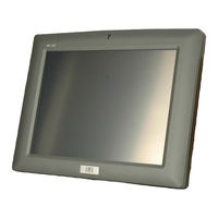
IEI Technology AFL-xxA-N26 User Manual (152 pages)
Fanless All-in-one Panel PC with 1.6GHz Intel Atom Processor TFT LCD, Wireless LAN, Touch Screen, RS-232/422/485 and IP 64 Protection
Brand:
IEI Technology
| Category:
Desktop
| Size: 6 MB
Table of Contents
Table of Contents
5
User Manual
1
Page
7
1 Introduction
15
Overview
16
Features and Model Variations
16
Figure 1-1: AFOLUX AFL-Xxa-N26 Flat Panel PC
16
Applications
17
External Overview
17
Table 1-1: Model Variations
17
Front Panel
18
Rear Panel
18
Figure 1-2: AFL-Xxa-N26 Front View
18
Figure 1-3: AFL-Xxa-N26 Rear View
18
I/O Interface Panel
19
Figure 1-4: AFL-10A-N26 I/O Interface Connector Panel
19
Top Panel and Side Panels
20
Figure 1-5: AFL-12A-N26 I/O Interface Connector Panel
20
Figure 1-6: AFL-Xxa-N26 Top View
20
Figure 1-7: AFL-10A-N26 Side View
20
Dimensions
21
AFL-W07A-N26 Dimensions
21
Figure 1-8: AFL-W07A-N26 Dimensions (MM)
21
AFL-08A-N26 Dimensions
22
Figure 1-9: AFL-08A-N26 Dimensions (MM)
22
AFL-10A-N26 Dimensions
23
Figure 1-10: AFL-10A-N26 Dimensions (MM)
23
AFL-12A-N26 Dimensions
24
Figure 1-11: AFL-12A-N26 Dimensions (MM)
24
Internal Overview
25
System Specifications
25
Table 1-2: AFL-Xxa-N26 Series System Specifications
26
2 Unpacking
27
Unpacking
28
Packing List
29
3 Installation
32
Anti-Static Precautions
33
Installation Precautions
33
Installation and Configuration Steps
34
Opening the System
34
Figure 3-1: Back Cover Retention Screws
35
Figure 3-2: AFL-W07A-N26 Aluminum Back Cover Retention Screws
35
Figure 3-3: AFL-08A-N26 Aluminum Back Cover Retention Screws
35
Msata Ssd Installation
36
Figure 3-4: AFL-10A-N26 Aluminum Back Cover Retention Screws
36
Figure 3-5: AFL-12A-N26 Aluminum Back Cover Retention Screws
36
Figure 3-6: Pcie Mini Slot Location
37
Figure 3-7: Pcie Mini Card Installation
37
Figure 3-8: Msata Card Thermal Pad
38
HDD Installation (AF-12A-N26 Only)
39
Figure 3-9: AF-12A-N26 HDD Bracket Retention Screws
39
Figure 3-10: AF-12A-N26 HDD Retention Screws
40
Figure 3-11: AF-12A-N26 HDD Installation
40
At/Atx Mode Selection
41
AT Power Mode
41
Figure 3-12: AT/ATX Switch Location
41
ATX Power Mode
42
Jumper Settings
42
Access the Jumpers
43
Preconfigured Jumpers
43
Table 3-1: Jumpers
43
Table 3-2: Preconfigured Jumpers
43
Clear CMOS Jumper
44
Table 3-3: Clear CMOS Jumper Settings
44
COM3 Port Pin 9 Select
45
Table 3-4: COM3 Pin 9 Setting Jumper Settings
45
Figure 3-13: Clear CMOS Jumper
45
Table 3-5: RS-232/422/485 Serial Port Select Jumper Settings
46
COM4 RS-422 and RS-485 Pinouts
47
Figure 3-14: COM3 Pin 9 Setting Jumper Location
46
RS-232/422/485 Serial Port Select Jumper
46
Table 3-6: RS-422 Pinouts
47
Table 3-7: RS-485 Pinouts
47
Mounting the System
48
Wall Mounting
48
Figure 3-15: RS-232/422/485 Serial Port Select Jumper Location
47
Figure 3-16: Wall-Mounting Bracket
49
Figure 3-17: Chassis Support Screws
50
Figure 3-18: Secure the Panel PC
51
Panel Mounting
51
Figure 3-21: AFL-10A-N26 Panel Opening
52
Figure 3-19: AFL-W07A-N26 Panel Opening
52
Figure 3-20: AFL-08A-N26 Panel Opening
52
Figure 3-22: AFL-12A-N26 Panel Opening
53
Figure 3-23: Tighten the Panel Mounting Clamp Screws
53
Arm Mounting
54
Figure 3-24: AFL-W07A-N26/AFL-08A-N26 Arm Mounting Retention Screw Holes
54
Cabinet and Rack Installation
55
Figure 3-25: AFL-10A-N26/AFL-12A-N26 Arm Mounting Retention Screw Holes
55
Figure 3-26: the Rack/Cabinet Bracket
56
Figure 3-27: Secure the Rack/Cabinet Bracket (AFL-10A-N26/AFL-12A-N26)
56
Bottom Panel Connectors
57
LAN Connection
57
Figure 3-28: Install into a Rack/Cabinet
57
Serial Device Connection (DB-9)
58
Figure 3-29: LAN Connection
58
Figure 3-30: Serial Device Connector
59
To DB-9 Serial Cable Connection
60
USB Device Connection
60
Figure 3-31: Serial Device Connector
60
Figure 3-32: USB Device Connection
61
4 System Maintenance
62
System Maintenance Introduction
63
Anti-Static Precautions
63
Turn off the Power
64
Opening the System
64
Replacing Components
64
Memory Module Replacement
64
Figure 4-1: AFL-10A-N26 SO-DIMM Socket Location
65
Figure 4-2: SO-DIMM Module Installation
65
Figure 4-3: Removing the Antennas
66
Figure 4-4: Releasing the WLAN Card
66
WLAN Module Replacement
66
Reinstalling the Covers
67
5 Ami Bios Setup
68
Introduction
69
Starting Setup
69
Using Setup
69
BIOS Menu Bar
70
Getting Help
70
Unable to Reboot after Configuration Changes
70
Table 5-1: BIOS Navigation Keys
70
BIOS Information
71
Main
71
System Date [XX/XX/XX]
71
Advanced
72
System Time [XX:XX:XX]
72
ACPI Settings
73
RTC Wake Settings
74
ACPI Sleep State [S1 (CPU Stop Clock)]
74
CPU Configuration
75
Wake System with Fixed Time [Disabled]
75
IDE Configuration
77
Configure SATA as [IDE]
77
USB Configuration
78
Hyper-Threading [Enabled]
77
Legacy USB Support [Enabled]
78
F81866 Super IO Configuration
79
Serial Port N Configuration
80
USB Devices
78
Change Settings [Auto]
80
Serial Port [Enabled]
80
Change Settings [Auto]
81
Serial Port [Enabled]
81
Change Settings [Auto]
82
F81866 H/W Monitor
83
Smart Fan Mode Configuration
83
Serial Port [Enabled]
82
Hardware Health Status
83
CPU Temperature N
84
CPU_FAN1 Smart Fan Control [Auto Duty-Cycle Mode]
84
SYS_FAN1 Smart Fan Control [Auto Duty-Cycle Mode]
84
Serial Port Console Redirection
85
Console Redirection [Disabled]
85
System Temperature N
85
Auto Recovery Function [Disabled]
86
Iei Feature
86
Chipset
87
Host Bridge Configuration
88
Intel IGD Configuration
88
South Bridge Configuration
89
Fixed Graphics Memory Size [128MB]
89
Restore AC Power Loss [Last State]
89
Power Saving Function [Disabled]
90
Set Spread Spectrum Fucntion [Disabled]
90
Boot
91
Bootup Numlock State [On]
91
Launch PXE Oprom [Disabled]
92
Option ROM Messages [Force BIOS]
92
Quiet Boot [Enabled]
92
UEFI Boot [Disabled]
92
Administrator Password
93
Security
93
User Password
93
Discard Changes and Reset
94
Restore Defaults
94
Save & Exit
94
Save Changes and Reset
94
Restore User Defaults
95
Save as User Defaults
95
6 Software Drivers
96
Available Software Drivers
97
Starting the Driver Program
97
Chipset Driver Installation
98
Figure 6-1: Drivers
98
Figure 6-2: Chipset Driver Screen
99
Figure 6-3: Chipset Driver Welcome Screen
99
Figure 6-4: Chipset Driver License Agreement
100
Figure 6-5: Chipset Driver Read Me File
101
Figure 6-6: Chipset Driver Setup Operations
101
Vga Driver Installation
102
Figure 6-7: Chipset Driver Installation Finish Screen
102
Figure 6-8: VGA Driver Read Me File
103
Figure 6-9: VGA Driver Setup Files Extracted
103
Figure 6-10: VGA Driver Welcome Screen
104
Figure 6-11: VGA Driver License Agreement
105
Figure 6-12: VGA Driver Read Me File
105
Figure 6-13: VGA Driver Setup Operations
106
Figure 6-14: VGA Driver Installation Finish Screen
106
Lan Driver Installation
107
Figure 6-15: LAN Driver Welcome Screen
107
Figure 6-16: LAN Driver Welcome Screen
108
Figure 6-17: LAN Driver Installation
108
Audio Driver Installation
109
Figure 6-18: LAN Driver Installation Complete
109
Figure 6-19: the Installshield Wizard Starts
109
Figure 6-20: Preparing Setup Screen
110
Figure 6-21: Installshield Wizard Welcome Screen
110
Figure 6-22: Audio Driver Software Configuration
111
Figure 6-23: Restart the Computer
111
Touch Screen Driver
112
Figure 6-24: Welcome Screen
112
Figure 6-25: License Agreement
113
Figure 6-26: Ready to Install the Program
113
Wireless Driver
114
Figure 6-27: Installing Penmount DMC9000
114
Figure 6-28: Reboot the Computer
114
Figure 6-29: Wireless Driver License Agreement
115
Figure 6-30: Wireless Driver Configuration Tool Options
116
Figure 6-31: Wireless Mode Select Window
116
Figure 6-32: Wireless Driver Installation
117
7 Interface Connectors
118
Peripheral Interface Connectors
119
Figure 7-1: Main Board Layout Diagram (Front Side)
119
Internal Peripheral Connectors
120
Figure 7-2: Main Board Layout Diagram (Solder Side)
120
Table 7-1: Peripheral Interface Connectors
121
Audio Speaker-Out Connector (CN3)
122
Audio MIC-In Connector (MIC1)
122
Audio DMIC-In Connector (DMIC1)
122
Table 7-2: Audio Line-Out Connector (CN3) Pinouts
122
Table 7-3: Audio MIC-In Connector (MIC1) Pinouts
122
Table 7-4: Audio DMIC-In Connector (DMIC1) Pinouts
122
Battery Connector (CN1)
123
COM2 Connector (COM2)
123
CPU Fan Connector (CPU_FAN1)
123
DIO Connector (DIO1)
123
Table 7-5: Battery Connector (CN1) Pinouts
123
Table 7-6: COM2 Connector Pinouts
123
Table 7-7: CPU Fan Connector (CPU_FAN1) Pinouts
123
Table 7-8: DIO Connector (DIO1) Pinouts
123
HDD LED Connector (HDD_CN1)
124
I2C Connector (CN4)
124
LVDS Connector (LVDS1)
124
Table 7-9: HDD LED Connector (HDD_CN1) Pinouts
124
Table 7-10: I2C Connector (CN4) Pinouts
124
Table 7-11: LVDS Connector (LVDS1) Pinouts
124
LVDS Backlight Connector (INVERTER1)
125
MCU Connector (JP8)
125
MCU Connector (HOTKEY_CN1)
125
Table 7-12: LVDS Backlight Connector (INVERTER1) Pinouts
125
Table 7-13: MCU Connector (JP8) Pinouts
125
Table 7-14: MCU Connector (HOTKEY_CN1) Pinouts
125
Pcie Mini Slot (M_PCIE1)
126
Table 7-15: Pcie Mini Card Slot (M_PCIE1) Pinouts
126
Pcie Mini Slot (M_PCIE2)
127
Table 7-16: Pcie Mini Card Slot (M_PCIE2) Pinouts
127
Power LED Connector (PW_LED1)
128
Power Button Connector (PW_BTN1)
128
SATA Power Connector (SATA_PWR1)
128
SATA Connector (SATA1)
128
Table 7-17: Power LED Connector (PW_LED1) Pinouts
128
Table 7-18: Power Button Connector (PW_BTN1) Pinouts
128
Table 7-19: SATA Power Connector (SATA_PWR1) Pinouts
128
Table 7-20: SATA Connector (SATA1) Pinouts
128
Touch Panel Connector (TS1)
129
TTL Panel Connector (CN6)
129
Table 7-21: Touch Panel Connector (TS1) Pinouts
129
USB Connector (USB1)
130
USB Connector (USB2)
130
Table 7-22: TTL Panel Connector (CN6) Pinouts
130
Table 7-23: USB Connector (USB1) Pinouts
130
Table 7-24: USB Connector (USB2) Pinouts
130
USB Connector (USB3)
131
USB2 and USB3 Power Connector (JP18)
131
External Interface Panel Connectors
131
Table 7-25: USB Connector (USB3) Pinouts
131
Table 7-26: USB2 and USB3 Power Connector (JP18) Pinouts
131
Table 7-27: Rear Panel Connectors
131
Audio Line-Out Connector (AUX1)
132
Ethernet Connector (LAN1, LAN2)
132
Power Connector (CN5)
132
Table 7-28: Audio Line-In Connector (AUX1) Pinouts
132
Table 7-29: Ethernet Connector (LAN1, LAN2) Pinouts
132
Table 7-30: Power Connector (CN5) Pinouts
132
Serial Port (COM1, RJ-45)
133
RS-232/422/485 Serial Port (COM3/COM4, DB-9)
133
Table 7-31: RS-232 Serial Port (COM1) Pinouts
133
Table 7-32: RS-232 Serial Port (COM3, DB-9) Pinouts
133
Table 7-33: RS-422 Serial Port (COM4, DB-9) Pinouts
133
Table 7-34: RS-485 Serial Port (COM4, DB-9) Pinouts
133
Reset Button Connector (RST1)
134
USB 2.0 Connectors (USB4)
134
VGA Connector (VGA1)
134
Table 7-35: Reset Button Connector (RST1) Pinouts
134
Table 7-36: USB 2.0 Connectors (USB4) Pinouts
134
Table 7-37: VGA Connector (VGA1) Pinouts
134
Preconfigured Jumper Settings
135
Backlight Voltage Selection Jumper (J_BL1)
135
Inverter ADJ Power Selection Jumper (JP6)
135
Inverter Power Selection Jumper (JP1)
135
Table 7-38: Preconfigured Jumpers
135
Table 7-39: Backlight Voltage Selection Jumper (J_BL1) Settings
135
Table 7-40: Inverter ADJ Power Selection Jumper (JP6) Settings
135
Table 7-41: Inverter Power Selection Jumper (JP1) Settings
135
LVDS Panel Voltage Selection Jumper (J_VLVDS1)
136
Table 7-42: LVDS Voltage Selection Jumper (J_VLVDS1) Settings
136
Table 7-43: Touchscreen Selection Jumper (J1) Settings
136
Touchscreen Selection Jumper (J1)
136
A Safety Precautions
137
Safety Precautions
138
General Safety Precautions
138
Anti-Static Precautions
139
Product Disposal
140
Maintenance and Cleaning Precautions
140
A.1.3 Product Disposal
140
Maintenance and Cleaning
140
A.2.2 Cleaning Tools
141
Cleaning Tools
141
B Bios Configuration Options
143
B.1 BIOS Configuration Options
144
Bios Configuration Options
144
C Watchdog Timer
146
Example Program
148
D Hazardous Materials Disclosure
149
Hazardous Material Disclosure Table for IPB Products Certified as Rohs Compliant under 2002/95/EC Without Mercury
150
Advertisement
Advertisement
Related Products
IEI Technology AFL-W15A-N270
IEI Technology AFL-W19B
IEI Technology AFL-42A-9652
IEI Technology AFL-08AH-N270-CR
IEI Technology AFL2-W15A-N270/L325
IEI Technology AFL3-12A/W15A-BT
IEI Technology AFOLUX AFL-315AW/B
IEI Technology AFL3-12A-BT
IEI Technology AFL3-W15A-BT
IEI Technology AFL3-08A-BT
IEI Technology Categories
Motherboard
Touch Panel
Computer Hardware
Single board computers
Desktop
More IEI Technology Manuals
Login
Sign In
OR
Sign in with Facebook
Sign in with Google
Upload manual
Upload from disk
Upload from URL