Table of Contents
Advertisement
Quick Links
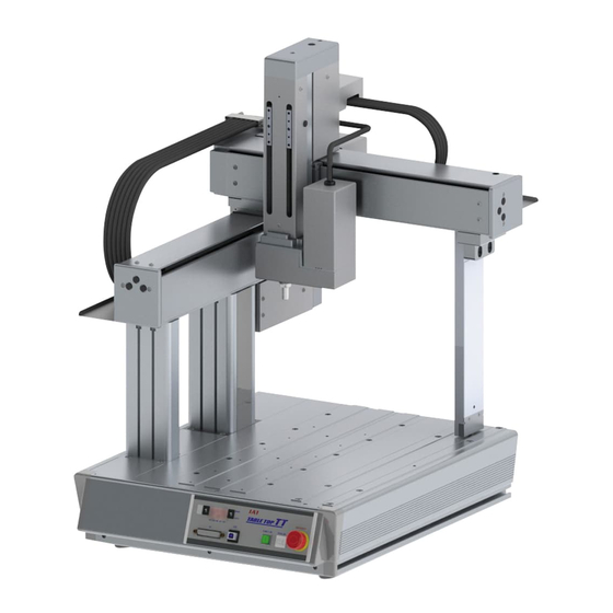
Table Top Type Robot TTA
First Step Guide Sixth Edition
Thank you for purchasing our product.
Make sure to read the Safety Guide and detailed Operation Manual (DVD) included with the product in
addition to this First Step Guide to ensure correct use.
This Operation Manual is original.
Warning : Operation of this equipment requires detailed installation and operation instructions
which are provided on the DVD Manual included in the box this device was
packaged in. It should be retained with this device at all times.
A copy of the DVD Manual can be requested by contacting your nearest IAI Sales
Office listed at the back cover of the Instruction Manual or on the First Step Guide.
• Using or copying all or part of this Operation Manual without permission is prohibited.
• The company names, names of products and trademarks of each company shown in the sentences
are registered trademarks.
Product Check
This product is comprised of the following parts if it is of standard configuration.
If you find any fault in the contained model or any missing parts, contact us or our distributor.
No.
Part Name
Model
Robot Main Unit (with
Refer to "How to read the model
1
built-in controller)
plate", "How to read the model"
Accessories
2
Power Supply Plug
AP-400-C
3
I/O Flat Cable
CB-PAC-PIO020
DFMC1.5/6-ST-3.5
4
(Supplier : Phoenix Contact)
Motor Power Connector
B2L 3.50/04/180 SN OR BX
For the AC Servo Motor
(Supplier : Weidmüller)
5
Type
Motor Power Connector
FKIC2.5HC/2-ST-5.08
For the Pulse Motor Type
(Supplier : Phoenix Contact)
MSTB2.5/5-STF-5.08AU
6
Cc-Link Connector
(Supplier : Phoenix Contact)
MSTB2.5/5-STF-5.08AUM
7
Devicenet Connector
(Supplier : Phoenix Contact)
8
Dummy Plug
DP-2
Power Cable
For the AC100V
9
Power Cable
For the AC200V
Main Body Mounting
Bracket
TTA-FT-4
For the X-axis stroke
20/30
10
Main Body Mounting
Bracket
TTA-FT-6
For the X-axis stroke
40/50
11
First Step Guide
12
Instruction Manual (DVD)
13
2. Optional Components
No.
Part Name
1
Main Body Mounting Bracket (with set bolts and nuts)
3. Teaching Tool (Option)
The personal computer application software or teaching pendant is required for the
Operations including program creation and setup such as position setting and parameter
setting with teaching. Use either of them.
No.
PC Software
1
(with RS232C cable + Emergency stop box)
PC Software
(USB conversion adapter + RS232C cable +
2
Cable and emergency stop box)
PC Software (with USB Cable + Dummy plug)
3
4
Touch panel teaching
5
Touch panel teaching (with deadman switch)
6
Teaching pendant
7
Teaching pendant (with deadman switch)
*1
The communication port on the left is for the personal computer and on the right is for the TTA.
4. Instruction Manuals related to this product, which are contained in the DVD.
No.
1
Table Top Type Robot TT Instruction Manual
2
PC software IA-101-X-MW Instruction Manual
3
Touch panel teaching TB-01, TB-01D, TB-01DR Instruction Manual
4
Teaching pendant SEL-T/TD Instruction Manual
5
DeviceNet Instruction Manual
6
CC-Link Instruction Manual
7
Profibus-Dp Instruction Manual
8
Ethernet/Ip Instruction Manual
9
EtherCAT Instruction Manual
*1
Applicable in Ver.1.16 and later with hardware revision "2"
Quantity
Reference
5. How to read the model plate
1
1
Enclosed in PU
Length depends
1 to 3
on indication of
I/O cable length
1
6. How to read the model
1
1
1 or 2
Enclosed in CC
1 or 2
Enclosed in DV
Enclosed in
global
specification
1
TTA-A□G and
TTA-C□G
Enclosed in 100V
1
AC type
Enclosed in 200V
1
AC type
4
6
1
1
1
Model
TT-FT
Part Name
Model
Reference
IA-101-X-MW
RS232C→RS232C *1
USB→RS232C *1
IA-101-X-USBMW
USB→USB *1
IA-101-TTA-USB
TB-01
–
TB-01D, TB01DR
–
SEL-T
–
SEL-TD
–
Name
Manual No.
ME0320
ME0154
ME0325
*1
ME0183
ME0124
ME0123
ME0153
ME0308
ME0309
Basic Specifications
[Common Specifications]
● Pulse Motor Type
Item
Specifications
Surrounding air
0 to 40°C, Room Humidity 20 to 85% or less
temperature/humidity
Motor Type
Stepping Motor (Servo Control)
Position detection method
Battery-less Absolute Encoder or Incremental Encoder
Ball Screw (X, Y-axis : φ12mm Z-axis : φ10mm Rolled C10)
Driving System
Ball Screw Lead X, Y-axis : 24 or equivalent, Z-axis : 12mm
± 0.02mm (X, Y, Z-axis), ± 0.015deg (R-axis) (Standard Specifications)
Positioning Repeatability
± 0.01mm (X, Y, Z-axis), ± 0.010deg (R-axis)
(High Resolution Specifications)
0.1mm or less (X, Y, Z-axis), 0.06deg or less (R-axis)
(Standard Specifications)
Backlash
0.05mm or less (X, Y, Z-axis), 0.06deg or less (R-axis)
(High Resolution Specifications)
Direct Driven Infinite Circulation Type
Guide
X-axis: Ma:15.9N・m
Mb: 15.9N・m
Y-axis: Ma:12.6N・m
Mb: 12.6N・m
Allowable Load Moment
* 1
Z-Axis: Ma: 9.7N・m
Mb: 9.7N・m
ZR-axis: Ma: 9.7N・m
Mb: 9.7N・m
* 1
Value found on the assumption of the life of 5000km run
● AC Servo Motor Type
Item
Specifications
Surrounding air
0 to 40°C, Room Humidity 20 to 85% or less
temperature/humidity
Motor Type
AC Servo Motor
Position detection method
Battery-less Absolute Encoder or Incremental Encoder
Ball Screw (X, Y-axis : φ12mm Z-axis : φ10mm Rolled C10 C5 or
equivalent)
Driving System
Ball Screw X, Y-axis : 8mm Z-axis : 3mm (Low Lead Specifications)
Ball Screw X, Y-axis : 16mm Z-axis : 6mm (High Lead Specifications)
± 0.005mm (X, Y, Z-axis), ± 0.015deg (R-axis) (Battery-less Absolute)
Positioning Repeatability
± 0.005mm (X, Y, Z-axis), ± 0.010deg (R-axis) (Absolute)
0.025mm or less (X, Y, Z-axis), 0.06deg or less (R-axis) (Battery-less
Absolute) (Low Lead)
Backlash
0.040mm or less (X, Y, Z-axis), 0.06deg or less (R-axis)
(Battery-less Absolute) (High Lead)
0.02mm or less (X, Y, Z-axis), 0.03deg or less (R-axis) (Absolute)
Guide
Direct Driven Infinite Circulation Type
X-axis: Ma:18.8N・m
Mb: 18.8N・m
Y-axis: Ma:14.9N・m
Mb: 14.9N・m
Allowable Load Moment
* 1
Z-axis: Ma: 11.5N・m
Mb: 11.5N・m
ZR-axis: Ma: 11.5N・m
Mb: 11.5N・m
* 1
Value found on the assumption of the life of 5000km run
[Individual Mechanism Specifications]
● Work Moving Type Pulse Motor Type
Max. Speed for Each Axes
Max.
Stroke [mm]
[mm/sec]
acceleration/
Type
deceleration
X Axis Y Axis Z Axis R Axis X Axis Y Axis Z Axis R Axis
Speed [G]
200
200
–
–
–
–
300
300
–
–
–
–
2-Axis
400
400
–
–
–
–
500
500
–
–
–
–
200
200
–
–
300
300
–
–
X, Y axis : 0.4
3-Axis
800
800
400
400
–
–
Z axis : 0.2
500
500
–
–
100/
400
200
200
150
1000
±180 /
300
300
4-Axis
±360
[deg
/
400
400
[deg]
sec]
500
500
*2
X Axis : 0.2G, Stroke 300mm or less, Y Axis : 0.4G, Stroke 700mm or less,
Z Axis : 0.2G, Stroke 50mm or less
Mc: 32.0N・m (Gate-shaped Type)
Mc: 37.4N・m
Mc: 20.5N・m
Mc: 20.5N・m
Mc: 37.8N・m (Gate-shaped Type)
Mc: 44.3N・m
Mc: 24.3N・m
Mc: 24.3N・m
Max. Load
Capacity [kg] *2
Weight
Model
[kg]
X
Y
Z
Axis
Axis
Axis
24.0
TTA-A2-*-2020
31.0
TTA-A2-*-3030
37.0
TTA-A2-*-4040
44.0
TTA-A2-*-5050
27.0
TTA-A3-*-2020
34.0
TTA-A3-*-3030
20
10
6
40.0
TTA-A3-*-4040
47.0
TTA-A3-*-5050
28.0
TTA-A4-*-2020
35.0
TTA-A4-*-3030
41.0
TTA-A4-*-4040
48.0
TTA-A4-*-5050
Advertisement
Table of Contents

Related Manuals for IAI TTA Series


Summary of Contents for IAI TTA Series
- Page 1 The communication port on the left is for the personal computer and on the right is for the TTA. Direct Driven Infinite Circulation Type A copy of the DVD Manual can be requested by contacting your nearest IAI Sales Guide Office listed at the back cover of the Instruction Manual or on the First Step Guide.
- Page 2 ● Work Fixing Type Pulse Motor Type ● Work Fixing Type Servo Motor High Lead Specifications < Rear Side> Max. Speed for Each Axes Max. Load Max. Speed for Each Axes Max. Load Max. Max. Stroke [mm] Stroke [mm] Capacity [kg] *2 Capacity [kg] *2 [mm/sec] acceleration/...
- Page 3 I/O Flat Cable (Accessories) CB-PAC-PIO020 I/O Signal Signal Cable Signal Cable Wiring Wiring 4. Noise Elimination Grounding (Frame Ground) Name Color Name Color Brown-1 OUT0 Brown-3 Connect it using a soft copper wire with the diameter of 1.6 mm or more to the frame ground Input Red-1 OUT1...
- Page 4 PROFIBUS-DP DeviceNet EtherCAT [Refer to the instruction manuals for PROFIBUS-DP] [Refer to the instruction manuals for DeviceNet] [Refer to the instruction manuals for EtherCAT] Monitor LED Monitor LED Illuminating, ×OFF, Flashing Monitor LED Illuminating, ×OFF, Flashing Monitor LED Monitor LED Illuminating, ×OFF, Flashing Indication...
- Page 5 Set both the I/O parameter No. 10 and No. 12 to “0”. Head Office: 577-1 Obane Shimizu-KU Shizuoka City Shizuoka 424-0103, Japan TEL +81-54-364-5105 FAX +81-54-364-2589 website: www.iai-robot.co.jp/ Technical Support available in USA, Europe and China Head Office: 2690 W. 237th Street, Torrance, CA 90505...
- Page 6 Tabletop Robot Instruction Manual 11th Edition IAI Corporation...
- Page 16 a et recautions or ur roducts...
- Page 22 Alert Indication...
- Page 25 About a et rotection ence...
- Page 31 ront ide Rear ide...
- Page 50 TTA A...
- Page 61 Correlation Graph for Pressing Force / Current Limit Value Current Limit Value [%]...
- Page 62 Correlation Graph for Pressing Torque / Current Limit Value 0. 8 5 0. 7 3 0. 6 1 0. 4 8 0. 3 7 0. 2 4 0. 1 2 Current Limit Value [%]...
- Page 63 High Lead Specification Low Lead Specification Current Limit Value [%] 0.70 0.60 0.53 0.50 0.40 0.46 0.30 0.38 0.15 0.30 0.20 0.23 0.10 0.08 0.00 Current Limit Value [%]...
- Page 68 Z-Axis, R-Axis - Direction X-Axis + Direction X:Mb Z:Mb Z-Axis Y-Axis Y-Axis R-Axis R:Mb X:Mc X:Ma X-Axis R:Ma...
- Page 69 X:Mb Z:Mb Z-Axis Y-Axis X-Axis R:Mb R:Ma...
- Page 70 1 Trape oid attern Trian le attern...
- Page 77 >...
- Page 79 External Power Source Load 24V DC +10% Output Terminal External Power Source Input Terminal 24V DC +10% Input Terminal External Power Source 24V DC +10% Output Terminal External Power Source Load 24V DC +10%...
- Page 81 Load Output Terminal External Power Source 24V DC +10% Output Terminal External Power Source Load 24V DC +10%...
- Page 89 2-φ 6.5 Through (L1) T-Groove Length: L2...
- Page 90 2-φ 6.5 Through (L1) T-Groove Length: L2 ti ness o loor or Installation...
- Page 91 Nominal Dimension Slotted Hole Nominal Dimension for Hole Pitch Detail of Oblong Hole T-Groove Product Width: 340...
- Page 92 Secure 2mm or more clearance in these areas Work Piece...
- Page 97 ront anel irin a out 5m /3m anel irin a out...
- Page 98 • • •...
- Page 99 • • TTA Pulse Motor Type 22. ENBS1-_TP 21. ENBS2+_TP 19. ENBS1-_TP 17. ENBS1+_TP 24. EMGS2-_TP 16. EMGS2+_TP Motor Drive ENBOK Circuit Status 13. EMGS1-_TP Detection 12. EMGS1+_TP SDWN Status Detection VP24S VP24S EMG SW...
- Page 102 DP-2 /TCPS 5.CTS 4.RTS 22.ENBS1-_TP 21.ENBS2+_TP 19.ENBS1-_TP 17.ENBS1+_TP 2-3 , 5- 6 MA N U 3-4 , 6- 7 A U T O AUTO 24.EMGS2-_TP 2 -3 , 5 -6 16.EMGS2+_TP TP Connected Motor Drive ENBOK 3 -4 , 6 -7 Status Circuit 13.EMGS1-_TP...
- Page 103 DP-2 /TCPS 5.CTS 4.RTS 22.ENBS1-_TP 21.ENBS2+_TP 19.ENBS1-_TP 2-3, 5-6 17.ENBS1+_TP : MANU 3-4, 6-7 : AUTO AUTO 24.EMGS2-_TP 2-3, 5-6 16.EMGS2+_TP : TP Connected Motor Drive ENBOK 3-4, 6-7 Circuit Status : TP 13.EMGS1-_TP Detection Unconnected 12.EMGS1+_TP /SDWN Status Detection VP24S VP24S EMG SW...
- Page 104 G9SA-301 (OMRON) G9SA-301 (OMRON) Electromagnetic Electromagnetic Contactor Contactor...
- Page 105 • • • / TCPS 5. CTS 4. RTS 22. ENBS1- _TP 21. ENBS2+_TP 19. ENBS1- _TP 2- 3, 5- 6 17. ENBS1+_TP : MANU 3- 4, 6- 7 : AUTO AUTO 24. EMGS2- _TP 2-3, 5-6 16. EMGS2+_TP 3rd, 4th axis 1st, 2nd axis : TP Connected Motor Drive...
- Page 106 • • 22. ENBS 1- _TP 21. ENBS 2+_TP 19. ENBS 1- _TP 17. ENBS 1+_TP 24. EMGS2- _TP 16. EMGS2+_TP 3rd, 4th axis 1st, 2nd axis ENBOK Motor Drive Motor Drive Status Circuit Circuit 13. EMGS1- _TP Detection 12. EMGS1+_TP / SDWN Status Detection...
- Page 107 / TCPS 5. CTS 4. RTS 22 .ENBS 1- _TP 21. ENBS 2+_TP 19. ENBS 1- _TP 2- 3, 5- 6 17. ENBS 1+_TP : MANU 3- 4, 6- 7 : AUTO AUTO 24. EMGS2- _TP 2-3, 5-6 16. EMGS2+_TP 3rd, 4th axis 1st, 2nd axis : TP Connected...
- Page 108 5. CTS / TCPS 4. RTS 22 .ENBS1- _TP 21. ENBS2+_TP 19. ENBS1- _TP 2- 3, 5- 6 17. ENBS1+_TP : MANU 3- 4, 6- 7 : AUTO 24. EMGS2- _TP AUTO 2-3, 5-6 3rd, 4th axis 1st, 2nd axis 16.
- Page 109 22 .ENBS1- _TP 21. ENBS2+_TP 19. ENBS1- _TP 17. ENBS1+_TP 24. EMGS2- _TP 3rd, 4th axis 1st, 2nd axis 16. EMGS2+_TP Motor Drive Motor Drive ENBOK Status Circuit Circuit Detection 13. EMGS1- _TP 12. EMGS1+_TP / SDWN Status Detection VP24S VP24S EMG SW 24 V...
- Page 110 22. ENBS 1- _TP 21. ENBS 2+_TP 19. ENBS 1- _TP 17. ENBS 1+_TP 24. EMGS2- _TP 3rd, 4th axis 1st, 2nd axis 16. EMGS2+_TP Motor Drive Motor Drive Status ENBOK Circuit Circuit Detection 13. EMGS1- _TP 12. EMGS1+_TP / SDWN Status Detection VP24S...
- Page 111 22. ENBS 1- _TP 21. ENBS 2+_TP 19. ENBS 1- _TP 17. ENBS 1+_TP 24. EMGS2- _TP 3rd, 4th axis 1st, 2nd axis 16. EMGS2+_TP Motor Drive Motor Drive Status ENBOK Circuit Circuit Detection 13. EMGS1- _TP 12. EMGS1+_TP / SDWN Status Detection 24 V...
- Page 124 PIO Connector BR- 1 BR- 3 Universal Output Port 316 OUT0 Service Power RD- 1 RD- 3 Universal Output Port 317 OUT1 Supply Switch OR- 1 OR- 3 Universal Output Port 318 OUT2 YW- 1 YW- 3 Universal Output Port 319 OUT3 GN- 1 GN- 3...
- Page 125 PIO Connector BR- 1 BR- 3 Service Power Universal Output Port 316 OUT0 Supply Switch RD- 1 RD- 3 Universal Output Port 317 OUT1 OR- 1 OR- 3 Universal Output Port 318 OUT2 YW- 1 YW- 3 Universal Output Port 319 OUT3 GN- 1 GN- 3...
- Page 126 0V(NPN Type) 24V DC(NPN Type) External External 24V DC(PNP Type) 0V(PNP Type) PIO Connector BR- 1 BR- 3 External Universal Output Port 316 OUT0 24V DC RD- 3 RD- 1 Universal Output Port 317 OUT1 OR- 1 OR- 3 Universal Output Port 318 OUT2 YW- 1 YW- 3...
- Page 127 0V(NPN Type) 24V DC(NPN Type) External External 24V DC(PNP Type) 0V(PNP Type) PIO Connector BR- 1 BR- 3 External Universal Output Port 348 OUT0 24V DC RD- 3 RD- 1 Universal Output Port 349 OUT1 OR- 1 OR- 3 Universal Output Port 350 OUT2 YW- 1 YW- 3...
- Page 132 No treatment conducted No treatment conducted Half Pitch MIL Socket HIF6-40D-1.27R (Hirose Electric) Flat Cable (20-core) × 2...
- Page 133 i nal a e olor irin ro n 1 Red 1 irin olor i nal a e ran e 1 ro n 1 ello reen 1 reen 1 lue 1 lue 1 urple 1 urple 1 ra 1 ra 1 hite 1 hite 1 lac 1...
- Page 134 Single-phase AC200 to 230V Grounding for Noise Prevention Have grounding between grounding terminal and metal frame with a cable Class D Grounding as fat and short as possible. (Security Grounding) Metal Frame Table Table Another Another Device Device Do not attempt to conduct in this way.
- Page 138 Main Power Initialization/self-diagnosis Normal operating condition Controller status Prior Supply Power supply for Status of power supply and connection peripheral devices diagnosed at initializing (DIO power supply and fieldbus setting at delivery) Cut the power off for the peripheral devices at the same time as or after cutting off main power Main Power Power supply for...
- Page 142 Min 0.01sec RDY output (output from the TTA) Intput port 019 Program execution Program...
- Page 193 μ...
- Page 265 each a is s ste coordinates or all the unit constructin a es is is ta en as the datu...
- Page 275 Extension I/O slot 1 (I/O2) E tension I lot 1 ser Released I hannel u ber ettin at eli er hannel Extension I/O slot 1 (I/O2) Status LED Extension I/O slot 2 (I/O3) E tension I ser Released I hannel u ber Status LED ettin at eli er ・...
- Page 280 Teaching Tool Extension Touch Panel SIO (CH2) Display Device Baud Rate : 115. . 2kbps Data Length : 8bi t Stop Bit Length : 1bi t Teaching Tool Varity Classification : None Connector (CH1)
- Page 284 rocedures to uppl rease on A es...
- Page 289 rocedures to uppl rease on R A is...
- Page 292 rocedures to Replace elt on A es...
- Page 307 rocedures to Replace elt on R A is...
- Page 364 2-φ6.5 Through (L1) The Length of the T Ditch : L2...
- Page 377 825, PhairojKijja Tower 12th Floor, Bangna-Trad RD., Bangna, Bangna, Bangkok 10260, Thailand TEL +66-2-361-4458 FAX +66-2-361-4456 The information contained in this document is subject to change without notice for purposes of product improvement. Copyright © 2017. Oct. IAI Corporation. All rights reserved. 17.10.000...
Need help?
Do you have a question about the TTA Series and is the answer not in the manual?
Questions and answers