Table of Contents
Advertisement
Advertisement
Table of Contents

Related Manuals for IAI TTA series


Summary of Contents for IAI TTA series
- Page 1 Tabletop Robot Instruction Manual 12th Edition IAI Corporation...
- Page 3 This Instruction Manual is original. The product cannot be operated in any way unless expressly specified in this Instruction Manual. IAI shall assume no responsibility for the outcome of any operation not specified herein. Information contained in this Instruction Manual is subject to change without notice for the purpose of product improvement.
-
Page 5: Table Of Contents
Table of Contents Safety Guideꞏꞏꞏꞏꞏꞏꞏꞏꞏꞏꞏꞏꞏꞏꞏꞏꞏꞏꞏꞏꞏꞏꞏꞏꞏꞏꞏꞏꞏꞏꞏꞏꞏꞏꞏꞏꞏꞏꞏꞏꞏꞏꞏꞏꞏꞏꞏꞏꞏꞏꞏꞏꞏꞏꞏꞏꞏꞏꞏꞏꞏꞏꞏꞏꞏꞏꞏꞏꞏꞏꞏꞏꞏꞏꞏꞏꞏꞏꞏꞏꞏꞏꞏꞏꞏꞏꞏꞏꞏꞏꞏꞏꞏꞏꞏꞏꞏꞏ1 Caution in Handingꞏꞏꞏꞏꞏꞏꞏꞏꞏꞏꞏꞏꞏꞏꞏꞏꞏꞏꞏꞏꞏꞏꞏꞏꞏꞏꞏꞏꞏꞏꞏꞏꞏꞏꞏꞏꞏꞏꞏꞏꞏꞏꞏꞏꞏꞏꞏꞏꞏꞏꞏꞏꞏꞏꞏꞏꞏꞏꞏꞏꞏꞏꞏꞏꞏꞏꞏꞏꞏꞏꞏꞏꞏꞏꞏꞏꞏꞏꞏꞏꞏꞏꞏꞏꞏꞏꞏꞏꞏꞏ8 International Standards Compliances ꞏꞏꞏꞏꞏꞏꞏꞏꞏꞏꞏꞏꞏꞏꞏꞏꞏꞏꞏꞏꞏꞏꞏꞏꞏꞏꞏꞏꞏꞏꞏꞏꞏꞏꞏꞏꞏꞏꞏꞏꞏꞏꞏꞏꞏꞏꞏꞏꞏꞏꞏꞏꞏꞏꞏꞏꞏꞏꞏꞏꞏꞏꞏꞏꞏꞏ9 Name and Function of Each Partꞏꞏꞏꞏꞏꞏꞏꞏꞏꞏꞏꞏꞏꞏꞏꞏꞏꞏꞏꞏꞏꞏꞏꞏꞏꞏꞏꞏꞏꞏꞏꞏꞏꞏꞏꞏꞏꞏꞏꞏꞏꞏꞏꞏꞏꞏꞏꞏꞏꞏꞏꞏꞏꞏꞏꞏꞏꞏꞏꞏꞏꞏꞏꞏꞏꞏꞏꞏꞏꞏ 10 Chapter 1 Specifications Check ............33 Product Check ....................33 1.1.1 Parts.........................33 1.1.2 Instruction Manuals Related to This Product, which are Contained in the Instruction Manual (DVD). - Page 6 1.3.2 Standard I/O Input and Output Interface..............64 1.3.3 Standard I/O Connector Pin Assignment ..............65 1.3.4 Extension I/O Input and Output Interface ..............66 1.3.5 Extension I/O Connector Pin Assignment..............67 1.3.6 Table for I/O Assignment..................68 1.3.7 Specifications for Service Power Supply Output .............71 Options ......................
- Page 7 3.4.2 Wiring for the Teaching Tool .................. 115 RS232C Interface ....................116 USB Interface......................117 3.4.3 Wiring of System I/O....................118 3.4.4 Wiring for PIO ......................119 IO Cable Layout...................... 119 IO Replacement Cable Layout................120 3.4.5 Grounding ......................121 3.4.6 Wiring for SIO Module Communication Cable............122 SIO Module 485 Communication Cable (one end with bare cut without connectors with no terminal finishing) ..............122 SIO Module 485 Communication Cable (one end with bare cut without...
- Page 8 Chapter 7 Appendix...............243 Work and Tool Coordinate System Features for Linear Axis ......243 7.1.1 Coordinates for Coordinate System Definition Unit..........244 Each Axis System ....................245 Base Coordinate System ..................246 Work Coordinate System..................248 Tool Coordinate System..................253 7.1.2 Setting of parameters ....................257 7.1.3 Caution Note......................260 Limitation in Coordinate System Constructing Axes..........260...
- Page 9 Three-Axis: X- Axis 400mm Stroke, Y-Axis 350mm Stroke, Z-Axis 100mm/ 150mm Stroke......................321 Three-Axis: X- Axis 500mm Stroke, Y-Axis 450mm Stroke, Z-Axis 100mm/ 150mm Stroke......................322 Four-Axis: X- Axis 300mm Stroke, Y-Axis 250mm Stroke, Z-Axis 100mm/ 150mm Stroke......................323 [10] Four-Axis: X- Axis 300mm Stroke, Y-Axis 250mm Stroke, Z-Axis 100mm/ 150mm Stroke......................324 [11] Four-Axis: X- Axis 400mm Stroke, Y-Axis 350mm Stroke, Z-Axis 100mm/...
- Page 10 Chapter 10 Life................359 Chapter 11 Warranty ...............361 11.1 Warranty Period....................361 11.2 Scope of the Warranty ..................361 11.3 Honoring the Warranty..................361 11.4 Limited Liability ....................361 11.5 Conditions of Conformance with Applicable Standards/Regulations, Etc., and Applications ....................362 11.6 Other Items Excluded from Warranty ..............
- Page 11 Safety Guide “Safety Guide” has been written to use the machine safely and so prevent personal injury or property damage beforehand. Make sure to read it before the operation of this product. Safety Precautions for Our Products The common safety precautions for the use of any of our robots in each operation. Operation Description Description...
- Page 12 Operation Description Description Transportation ● When carrying a heavy object (approx. 20kg or more, with a heavy load warning sign), do the work with two or more persons or utilize equipment such as a hand cart or crane. ● When the work is carried out with 2 or more persons, make it clear who is to be the leader and who to be the follower(s) and communicate well with each other to ensure the safety of the workers.
- Page 13 Operation Description Description Installation (2) Cable Wiring and Start ● Use our company’s genuine cables for connecting power supply, and for the teaching tool. ● Make sure that the wiring of the power supply cable with a ring tongue terminal for 200V is conducted by a person who has knowledge of electricity and make sure that there is no looseness in fastening.
- Page 14 Operation Description Description Installation (4) Safety Measures and Start ● When the work is carried out with 2 or more persons, make it clear who is to be the leader and who to be the follower(s) and communicate well with each other to ensure the safety of the workers. ●...
- Page 15 Operation Description Description Trial ● When the work is carried out with 2 or more persons, make it clear who Operation is to be the leader and who to be the follower(s) and communicate well with each other to ensure the safety of the workers. ●...
- Page 16 (who has read the contents of the instruction manual narrowly and understands how to use, or who has attended to the necessary trainings held by IAI). ● Work operation in any trouble or maintenance is also allowed only to the...
- Page 17 Alert Indication The safety precautions are divided into “Danger”, “Warning”, “Caution” and “Notice” according to the warning level, as follows, and described in the instruction manual for each model. Level Degree of Danger and Damage Symbol This indicates an imminently hazardous situation which, if the Danger Danger product is not handled correctly, will result in death or serious...
- Page 18 Caution in Handling 1. Make sure to follow the usage condition, environment and specification range of the product. In case it is not secured, it may cause a drop in performance or malfunction of the product. 2. Do not conduct any treatment or operation that is not stated in this instruction manual.
- Page 19 Rescue at Emergency It is recommended to construct a safety protection fence by 2.4 around this robot and that an operator works outside the safety protection fence. In case of you getting stuck in this robot; 1) Press the emergency stop switch, and the X and Y-axes stay at the position and Z-axis will be available to make move manually by the brake release switch on the front panel, or 2) After cutting off the power supply immediately by taking the power supply cord off the inlet, it is available to release mechanically with the slider position tuning volume (Z-axis).
- Page 20 About Safety Protection Fence Considering safety, it is recommended to have a safety protection fence to prevent possible danger. For Machinery Directive (2006/42/EC) in EU Directives, equip with safety protection fence. Use a system I/O connector at the entrance of the safety protection fence to equip with an interlock system which makes the emergency stop works when the entrance is opened, and make sure to avoid entering from nowhere else but the entrance.
- Page 21 Dimensions for Safety Protection Fence Secure 200mm at least above the product dimensions for the dimensions of the safety protection fence. 200 or 200 or Width of Product more more Width of Safety Fence...
- Page 22 International Standards Compliances This robot complies with the following overseas standard. However, check with our sales person at the order for the model names for the CE marking compliable model and KCs marking compliable model as they differ from the name for the standard ones.
-
Page 26: Name And Function Of Each Part
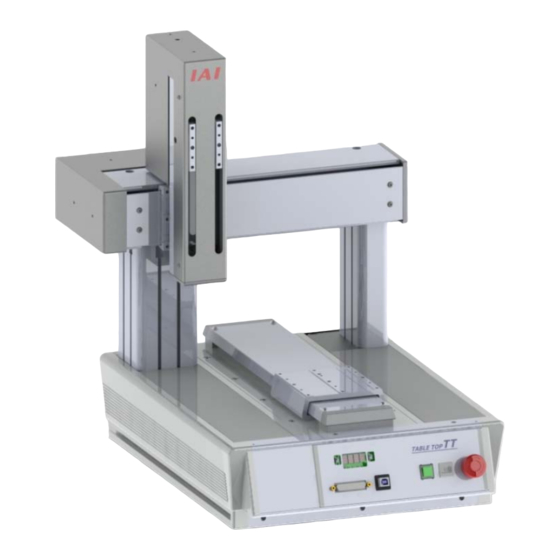
Name and Function of Each Part <Front Side> Slider Position Adjustment Volume (Z-Axis) Z-Axis Grease Supply Inlet (Z-Axis) Y-Axis Grease Supply Inlet (Y-Axis) T-Grooves (×2) Slider Position Adjustment Volume (Y-Axis) X-Axis T-Grooves (×2) T-Groove Front Panel <Rear Side> Grease Supply Inlet (Z-Axis) T-Grooves (×2) Slider Position Adjustment T-Groove... - Page 27 <Details of Front Panel> 2) Panel Window 1) Brake Releasing Switch (3rd axis) 4) Emergency Stop Switch 3) Operation Mode Switch 5) Program Switch 8) Teaching Tool Connector 7) USB Connector 6) Function Switch (Start Switch) 1) Brake Releasing Switch (3rd axis) It is a switch to release the Z-axis brake.
- Page 28 2) Panel Window It is constructed with four digits of 7-seg LEDs that shows the status of the equipment and five LED lamps. The table below shows the status when each LED lamp is turned on. Display Name Status Description Color PIO program operation is available.
- Page 29 Core Display Specifications Display Priority Description (Note 1) Cold-start level error Operation-cancellation level error Message level error In updating mode Jump to the application Core flash ROM check process Application flash ROM check process SDRAM check process Note 1: Smaller numbers show more priority than bigger ones. 3) Operation Mode Switch It is a switch to indicate the operation mode of Table-Top Robot.
- Page 30 6) Function Switch (Start Switch) It is a switch to start up the program set on the 5) Program Switch. This switch is enabled in the AUTO mode. AUTO Mode/MANU Mode are to be switched over on 3) Operation Mode Switch. In the MANU mode, this switch is enabled after the teaching pendant or PC software has been connected online.
- Page 31 <How to Take off Front Panel> [For Operation Part Removable Type (OS)] 1) Detach the front base cap. 2) Detach the front base cover by sliding it. Front Base Cap ② Front Base Cover 3) Detach the screws (2 places). Screw Screw...
- Page 32 <Details of Rear Panel> 12) Expanded I/O Slot 1 (I/O2) 13) Standard I/O Service Power Status LED Supply Connector 11) Expanded I/O Slot 1 (I/O2) 14) System I/O Connector 9) AC Inlet 10) Power Switch 15) Motor Power Supply 19) FG Terminal 16) Service Power Switch Connector 18) Expanded I/O Slot 2 (I/O3)
- Page 33 12) Expanded I/O Slot 1 (I/O2) Status LED 18) Expanded I/O Slot 2 (I/O3) Status LED Depending on the mounted module, the status shown below will be displayed. • DIO Type (NPN/PNP Specification) Status LED Expanded I/O2 Expanded I/O3 Display Name Status Description...
- Page 34 • PROFIBUS-DP Status LED Expanded I/O2 Expanded I/O3 Display Name Status Description Color Illuminated Online Green Flashing Online (cleared) An error occurred (Parameterizing error or PROFIBUS Orange Illuminated configuration error) Illuminated Initializing complete Green Flashing Initializing complete (with diagnosis event) Orange Illuminated An error occurred (exceptional error)
- Page 35 13) Standard I/O Service Power Supply Connector It is a general-purposed input and output connector to connect peripheral devices. It is a flat connector with 40 pins. It is available for DIO connection of 16 points of general-purposed input and 16 points of general-purposed output. With 16) Service Power Switch, the power can be supplied externally as the I/O power supply and internally as the I/O circuit power supply.
- Page 36 15) Motor Power Supply Connector It is a motor power input and output connector (MPO/MPI) for the external drive cutoff. Pulse Motor Type Signal Pin No. Description Name Motor drive power output Motor drive power input AC Servo Motor Type Signal Pin No.
- Page 37 About Coordinate System The coordinate system of the coordinate system definition unit consists of four coordinates (X-axis, Y-axis, Z-axis and R-axis) at the maximum. The coordinate value on the home of each axis is 0mm of the position data. The position from the home is the position data for each axis. For TTA, there are three types of coordinate systems in addition to the coordinate system defined for each axis (each axis system), which are base coordinate system, work coordinate system and tool coordinate system.
- Page 38 2. Base Coordinate System It is the coordinate system to indicate the position of the datum point for tool installation against the work piece mount face. Work Coordinate System No. 0 (work coordinate system offset 0) = Base Coordinate System. X axis of Base Coordinate System is described as Xb, Y axis as Yb, Z axis as Zb and R axis as Rb.
- Page 39 Also, when a work piece is mounted on an axis of either X, Y or Z-axis, the positive side of the base coordinate system is the opposite direction of the operation direction of the physical axis. For instance, in below explains for when a work piece is mounted on the X-axis in TTA-A4 (XYZ Home Standard Specification).
- Page 40 3. Work Coordinate System It is the 32 kinds of coordinate systems defined by the offset of each axis against the base coordinate system. Work Coordinate System No. 0 is reserved as Base Coordinate System (= Work Coordinate System Offset = 0) by the system. Set the offset of each axis as described below.
- Page 41 Tool Coordinate System It is the 128 kinds of coordinate systems defined by the too (such as hand) dimensions (offset) of that attached on the tool attached position. Work Coordinate System No. 0 is reserved as offset = 0 of Tool Coordinates by the system. Select the defined tool coordinate system number, and it is used as the destination point at positioning of the tool tip as well as the tool attached position.
-
Page 43: Chapter 1 Specifications Check
Chapter 1 Specifications Check Product Check This product is comprised of the following parts if it is of standard configuration. See the component list for the details of the enclosed components. If you find any fault in the contained model or any missing parts, contact us or our distributor. 1.1.1 Parts Part Name... -
Page 44: Instruction Manuals Related To This Product, Which Are Contained In The Instruction Manual (Dvd)
1.1.2 Instruction Manuals Related to This Product, which are Contained in the Instruction Manual (DVD). Name Manual No. Instruction Manual ME0320 PC Software IA-101-X-MW/IA-101-X-USBMW Instruction Manual ME0154 Touch Panel Teaching TB-02 Instruction Manual ME0355 Touch Panel Teaching TB-01, TB-01D, TB-01DR Instruction Manual ME0325 (Note 1) Teaching Pendant SEL-T/TD/TG Instruction Manual... -
Page 45: How To Read The Model
RS485 connection board Note 1 It may be displayed for IAI use. (It is not a code to show the model type.) Note 2 2 pieces of EtherNet/IP cannot be selected to the extension I/O slot. <Extension Slot 1>... - Page 46 *1 Type : Pulse motor, (Work moving) 2-axis : Pulse motor, (Work moving) 2-axis, Global specification : Pulse motor, (Work moving) 3-axis Pulse motor, (Work moving) 3-axis、Global specification Pulse motor, (Work moving) 4-axis Pulse motor, (Work moving) 4-axis, Global specification Pulse motor, (Work fixing) 2-axis Pulse motor, (Work fixing) 2-axis, Global specification Pulse motor, (Work fixing) 3-axis...
-
Page 47: Model Codes For Option Of Y-Axis Mount Position Change
1.1.5 Model Codes for Option of Y-axis Mount Position Change Higher in +50mm Higher in +100mm Standard from standard from standard Model code for changed in Y-axis mounting position in height Forward in +90mm Forward in +180mm Standard from standard from standard Model code for changed in Y-axis... -
Page 48: Model Code For Zr Axis Front-Back Direction Position Change Option
1.1.6 Model Code for ZR Axis Front-Back Direction Position Change Option 64.5mm forward to Standard standard ZR Axis Front-Back Direction Position Change Model Code Standard Position 55.5mm 120mm (Standard) FZ (Forward in 64.5mm from standard) -
Page 49: Mechanical Specifications
Mechanical Specifications 1.2.1 Speed [1] Work Moving Type Pulse Motor Specifications Restriction on Speed Unit [mm/s] 2020 3030 4040 5050 Model 2020-10B/15B 3030-10B/15B 4040-10B/15B 5050-10B/15B 2020-10B/15B-R1/R2 3030-10B/15B-R1/R2 4040-10B/15B-18L/36L 5050-10B/15B-18L/36L Axis 1000 [deg/sec] [2] Work Fixing Type Pulse Motor Specifications Restriction on Speed Unit [mm/s] 2015 3025... -
Page 50: Work Fixing Type Servo Motor Low Lead Specifications
[5] Work Fixing Type Servo Motor Low Lead Specifications Restriction on Speed Unit [mm/s] 2020 3030 4040 5050 Model 2020-10B/15B 3030-10B/15B 4040-10B/15B 5050-10B/15B Axis 2020-10B/15B-R1/R2 3030-10B/15B-R1/R2 4040-10B/15B-18L/36L 5050-10B/15B-18L/36L 1500 [deg/sec] [6] Work Fixing Type Servo Motor High Lead specification Restriction on Speed Unit [mm/s] 2020 3030... -
Page 51: Max. Speed, Max. Acceleration Speed And Transportable Mass
1.2.2 Max. Speed, Max. Acceleration Speed and Transportable Mass [1] Work Moving Type Pulse Motor Specifications When the transported weight is low, the acceleration/deceleration and speed can be increased. Transportable Mass Unit: [kg] Max. Speed [mm/s] 50 or 100 or 200 or 300 or 400 or... -
Page 52: Work Moving Type Servo Motor Low Lead Specifications
• R-axis Type Transportable Mass Unit: [kgꞏm 200 or 300 or 400 or 500 or 600 or 700 or 800 or 900 or 1000 Angular Velocity [deg/s] less less less less less less less less or less Allowable Load Moment of 0.01 0.008 0.006... -
Page 53: Work Fixing Type Servo Motor Low Lead Specifications
[5] Work Fixing Type Servo Motor Low Lead Specifications When the transported weight is low, the acceleration/deceleration and speed can be increased. Transportable Mass Unit: [kg] Acceleration [G] Axis 0.15 or less 0.2 or less 0.3 or less [6] Work Fixing Type Servo Motor High Lead Specifications When the transported weight is low, the acceleration/deceleration and speed can be increased. -
Page 54: Driving System And Position Detector
1.2.3 Driving System and Position Detector [1] Pulse Motor Standard Specifications Ball Screw Type No. of Encoder Axis Motor Type Lead [mm] Diameter Pulses Type Accuracy [mm] □56 Stepping motor 24 or equivalent Rolled 12 □56 Stepping motor 24 or equivalent Rolled ... -
Page 55: Positioning Repeatability, Lost Motion (Note 1)
1.2.4 Positioning Repeatability, Lost Motion (Note 1) [1] Pulse Motor Standard Specifications Axis Positioning Repeatability [mm] Lost Motion [mm] (Note 2) ±0.02 0.1 or less ±0.02 0.1 or less ±0.02 0.1 or less ±0.015 [deg] 0.06deg or less [2] Pulse Motor High Resolution Specifications Axis Positioning Repeatability [mm] Lost Motion [mm]... -
Page 56: Relation Between Current Limit Value And Pressing Force
1.2.5 Relation between Current Limit Value and Pressing Force [1] Pulse Motor Specifications • Z-Axis Current Limit Value [%] Pressing Force [N] Fluctuation in Pressing Force: ±10%F.S Correlation Graph for Pressing Force / Current Limit Value Current Limit Value [%] Caution: (1) The relation of the current limit value and the pressing force is a reference when assuming the speed is 20mm/s. - Page 57 • R-Axis Current Limit Value [%] Pressing Torque [Nꞏm] 0.12 0.24 0.37 0.48 0.61 0.73 0.85 Fluctuation in Pressing Torque: ±10%F.S Correlation Graph for Pressing Torque / Current Limit Value 0. 8 5 0. 7 3 0. 6 1 0. 4 8 0.
-
Page 58: Servo Motor Specifications
[2] Servo Motor Specifications • Z-Axis Pressing Force [N] Current Limit Value [%] Low Lead Specification High Lead Specification Fluctuation in Pressing Force: ±10%F.S High Lead Specification Low Lead Specification Current Limit Value [%] • R-Axis Current Limit Value [%] Pressing Torque [Nꞏm] 0.08 0.15... -
Page 59: Allowable Moment For Actuator
1.2.6 Allowable Moment for Actuator [1] Work Moving Type Pulse Motor Specifications • 2-Axis Type Allowable Static Load Allowable Dynamic Load Moment [N•m] Moment [N•m] Axis Overhang load length [L] Ma direction: 190mm or less 62.7 62.7 126.5 15.9 15.9 32.0 Mb or Mc direction : 240mm or less Ma direction: 170mm or less... -
Page 60: Work Fixing Type Pulse Motor Specifications
[2] Work Fixing Type Pulse Motor Specifications • 2-Axis Type Allowable Static Load Allowable Dynamic Load Moment [N•m] Moment [N•m] Axis Overhang load length [L] 47.9 47.9 142.1 12.6 12.6 37.4 Ma direction: 170mm or less 47.9 47.9 142.1 12.6 12.6 37.4 Mb or Mc direction: 210mm or less... -
Page 61: Work Moving Type Servo Motor Specifications
[3] Work Moving Type Servo Motor Specifications • 2-Axis Type Allowable Static Load Allowable Dynamic Load Moment [N•m] Moment [N•m] Axis Overhang load length [L] Ma direction: 190mm or less 62.7 62.7 126.5 18.8 18.8 37.8 Mb or Mc direction: 240mm or less Ma direction: 170mm or less 47.9 47.9... -
Page 62: Work Fixing Type Servo Motor Specifications
[4] Work Fixing Type Servo Motor Specifications • 2-Axis Type Allowable Static Load Allowable Dynamic Load Moment [N•m] Moment [N•m] Axis Overhang load length [L] 47.9 47.9 142.1 14.9 14.9 44.3 Ma direction: 170mm or less 47.9 47.9 142.1 14.9 14.9 44.3 Mb or Mc direction: 210mm or less... -
Page 63: Ma Direction Moment Offset Datum Position And The Moment Direction Of Each Axis
1.2.7 Ma Direction Moment Offset Datum Position and the Moment Direction of Each Axis • Work Moving Type [Ma Direction Moment Offset Datum Position] Z-Axis Ma Direction Moment Offset Datum Position Y-Axis Ma Direction Moment Offset Datum Position [Moment Direction of Each Axis] [Rotary direction for R-Axis] Z-Axis, R-Axis - Direction... - Page 64 • Work Fixing Type [Ma Direction Moment Offset Datum Position] Z-Axis Ma Direction Moment Offset Datum Position X-Axis Ma Direction Moment Offset Datum Position Y-Axis Ma Direction Moment Offset Datum Position [Moment Direction of Each Axis] X:Mb Z:Mb Z-Axis Y-Axis X-Axis R:Mb R:Ma...
-
Page 65: Duty Of Continuous Operation
1.2.8 Duty of Continuous Operation Perform operation at the allowable duty or below. [How to Calculate Duty] Figure out the load factor LF and acceleration / deceleration time ratio tod, and read the reference for the duty from the graph. There are two patterns as shown below depending on the movement distance and acceleration / deceleration, and the way to calculate differs for each. - Page 66 c) Cycle Time tc* 1) For Trapezoid Pattern Assume the times for acceleration range and deceleration range as the acceleration time ta [s] and deceleration time tb [s]; Acceleration/deceleration time ta(tb) = (Set Velocity V [mm/s] / Acceleration / deceleration at operation α [mm/s ] ) [s] Acceleration/deceleration movement distance Sa (Sb) = (Acceleration / deceleration at operation α[G] x 9800 [mm/s...
- Page 67 LF=50% less than LF=50% less than LF=50% less than LF=50% less than LF=50% less than LF=50% less than Acceleration/deceleration Time Ratio [Example for Duty Calculation for TTA] In below, shows an example for operation of the four-axis model TTA-A4SLG-WA-50-50-15B///. Example 1) X-axis Calculate the duty of when;...
- Page 68 Constant velocity range movement distance S = Stroke St – Acceleration/deceleration movement distance (Sa + Sb) [mm] = 500 – (123.55 + 123.55) = 252.9 Cycle time tcr = Constant velocity range movement distance S [mm] / Set Velocity V [mm/s] + Acceleration timeta [s] + Deceleration time tb [s] + Positioning convergence time [s] = 252.9/600 + 0.41+0.41+0.15 = 1.39 [s]...
- Page 69 Acceleration/Deceleration Time Ratio tod = (Acceleration Tim at Operation ta + Deceleration Time at Operation tb) / Cycle Time tct = (0.23+ 0.23) / 0.61 = 0.75 (75 %) In e), the reference of the duty will be 90% when the load factor LF = 70% and acceleration / deceleration time ratio tod = 75% according to the graph.
-
Page 70: Electrical Specifications
Electrical Specifications Item Description Power supply Voltage AC100 to 230V ±10% Power Supply Frequency Range 50/60Hz ±5% Pulse Motor 2.9A/1.2A (AC100/230V, when rated load) Current 2-axis type: 2.9A/1.2A (AC100/230V, when rated load) Consumption Servo Motor 3-axis, 4-axis type: 5.8A/2.4A (AC100/230V, when rated load) Service Power Output (For I/O) 24V DC ±10% MAX. - Page 71 Item Description Between primary – secondary 1500V AC For 1 minute Withstanding Voltage Between primary – FG 1500V AC For 1 minute Current Leakage 0.75mA or less Grounding 10A 1.0V or less (for 10 seconds) Protection Function against Electric Class basic insulation Shock Cooling Method Forced Air-Cooling...
-
Page 72: Protection Circuit
1.3.1 Protection Circuit Although there are fuses mounted in this robot for purpose of protecting the circuit, it is not what a customer can replace. With sufficient margin in design, it is a rear case that the fuses get broken, but please make sure to set up a breaker shown below external before starting to use. -
Page 73: Selection Of Leakage Breaker
[2] Selection of Leakage Breaker • Regarding the leakage breaker, it is necessary to have a clear purpose for selection such as a fire protection or protection of human body. • Leak current varies depending on the capacity of connected motor, cable length and the surrounding environment. -
Page 74: Standard I/O Input And Output Interface
1.3.2 Standard I/O Input and Output Interface Input Section Output Section Input Voltage 24V DC ±10% Load Voltage 24V DC ±10% Input Current 7mA / per output Min. 16V DC (NPN) 100mA / per circuit, ON/OFF 8V DC (PNP) Load Current (Note 1) 400mA / 8 ports... -
Page 75: Standard I/O Connector Pin Assignment
1.3.3 Standard I/O Connector Pin Assignment Standard I/O Connector Pin Assignment Pin No. Category Assignment Pin No. Category Assignment (Note 1) OUT0 (Note 1) OUT1 OUT2 OUT3 OUT4 OUT5 OUT6 OUT7 Output OUT8 OUT9 OUT10 OUT11 Input OUT12 OUT13 IN10 OUT14 IN11 OUT15... -
Page 76: Extension I/O Input And Output Interface
1.3.4 Extension I/O Input and Output Interface Input Section Output Section Input Points 16 points Output Points 16 points Input Voltage 24V DC ±10% Load Voltage 24V DC ±10% Input Current 4mA / per output Load Current 50mA/1 per circuit ON/OFF Min. -
Page 77: Extension I/O Connector Pin Assignment
1.3.5 Extension I/O Connector Pin Assignment Extension DIO Connector Pin Assignment Pin No. Category Assignment Pin No. Category Assignment (Note 1) OUT0 (Note 1) OUT1 OUT2 OUT3 OUT4 OUT5 OUT6 OUT7 Output OUT8 OUT9 OUT10 OUT11 Input OUT12 OUT13 IN10 OUT14 IN11 OUT15... -
Page 78: Table For I/O Assignment
1.3.6 Table for I/O Assignment 1) When I/O2 is Not Fieldbus type (Type of extension I/O is either of E/NP/SE1/SE2/IA) The functions described in brackets [ ] are not set at the delivery. Type Port No. Function Type Port No. Function Program Start ALM (LED on the front panel) - Page 79 2 ) When I/O2 is Fieldbus type (Type of extension I/O is either of CC/DV/PR/EP/EC) The functions described in brackets [ ] are not set at the delivery. Type Port No. Function Type Port No. Function Program Start ALM (LED on the front panel) Switch No.
- Page 80 ◎ Coution for I/O Assignment of Switches from Switch No. 1 (Additional Switch) to Switch No. 4 (Additional Switch) Switch No. 1 (additional switch) should be connected to Port No. 001 and assigned. Therefore, if the setting of Input Function Select 001 in I/O Parameter No. 31 is 0, general-porpose input, the switch should be for the general-porpose input.
-
Page 81: Specifications For Service Power Supply Output
1.3.7 Specifications for Service Power Supply Output By having the service power switch set the service power output ON, power supply to the standard I/O circuit and service power output from the standard I/O connector can be conducted. (It becomes unnecessary to prepare I/O power source externally.) Specifications for Service Power Supply Output Output Voltage... -
Page 82: Options
Options 1.4.1 X, Y and Z-Axes Options [1] Home-Position Check Sensor (Model: HS) For the normal home-return operation of the single axis robots, “Pressing System” is adopted which determines the home position by detecting the Z-phase after pressing the slider to the stopper and reversing it. -
Page 83: Chapter 2 Installation
Chapter 2 Installation Transportation (1) Handling the Packed Unit • Do not damage or drop. The package is not applied with any special treatment that enables it to resist an impact caused by a drop or crash. • Transport a heavy package with at least more than two operators. Consider an appropriate method for transportation. -
Page 84: How To Install
How to Install This chapter explains how to install the actuator on your mechanical system. 2.3.1 Installation Orientation Do pay attention to these items. ○: Available ×: Not available Horizontal Sideways Ceiling Mount Installation lnstallation Installation ○ × × Installation Orientation Horizontal Installation Sideways lnstallation Ceiling Mount Installation... -
Page 85: How To Fix Unit
2.3.2 How to Fix Unit This product is equipped with rubber legs that provide the structure to prevent from moving the unit easily during its operation. There may be a case that the unit moves depending on the condition of use (such as load weight or acceleration/deceleration speed). -
Page 86: Work Fixing Type
[2] Work Fixing Type 2-φ 6.5 Through (L1) T-Groove Length: L2 Model 2015 3025 4035 5045 Stiffness of Floor for Installation As large reaction force is applied to the platform to install a robot, it is necessary to prepare a platform with enough stiffness. -
Page 87: Attachment Of The Transported Object
To affix the unit, purchase the unit fixing bracket in option or prepare a bracket separately. When you make your own bracket, have oblong holes to secure margin to the pitch between holes in the direction of the product width, and make sure the straight portion on the oblong holes is 3mm or more. -
Page 88: Loadable Weight On Table
2.3.4 Loadable Weight on Table Refer to the table below for the weight available to load on TTA Table portion (top surface of main unit, portion other than the slider for the table moving type). Loadable Weight on Table Model Mass [kg] A-2020 A-3030... -
Page 89: How To Attach Supportive Tools
2.3.5 How to Attach Supportive Tools There are T-grooves equipped on the main unit and the frame to support the Y-axis. By using a nut, supportive tools can be attached. It is recommended to apply a T-nut or square nut on the T-groove, but a hexagon nut can also be used. Pay attention to the screw length so the tip of the screw would not touch the bottom of the T-groove when attaching. -
Page 90: Procedures To Detach Operation Part
Procedures to Detach Operation Part In this section, explains how to detach the operation part in the detachable operation option. <Required Tools/Measurement Equipment> None... - Page 91 [Detaching Operation Part Step (1)] Dedicated Screws Take off the dedicated screws (2pcs) on the front cover side. Dedicated screws can be taken off with hand. Front Cover [Detaching Operation Part Step (2)] Pull the front cover to the front direction to take it off.
- Page 92 [Detaching Operation Part Step (4)] Cable Case Pull out the operation part to the front direction. The cable to connect the operation part and the main unit is stored in the cable case. [Detaching Operation Part Step (5)] Attach the front cover if necessary.
-
Page 93: Chapter 3 Wiring
Chapter 3 Wiring Wiring Diagram Front Panel Wiring Layout Touch Panel Teaching (Option) Model: TB-01-S 5m /3m PC Software PC Connection Cable (Option) (Enclosed in PC Software) Model: CB-ST-E1MW050 (5m) Model: IA-101-X-MW CB-SEL-USB030 (3m) IA-101-TT-USB CB-ST-AIMW050 (5m) IA-101-X-USBMW Dummy Plug IA-101-XA-MW Model: DP-2 * Enclosed in global type and PC Software (IA-101-TTA-USB) -
Page 94: Power Supply, Emergency Stop Circuit And Enable Circuit
Power Supply, Emergency Stop Circuit and Enable Circuit With the wiring to the inlet and system I/O connectors, power supply circuit and safety circuit (external and built-in emergency stop circuit and external enable circuit) can be constructed. Safety circuit is a circuit that is to be prepared to stop the robot operation manually to prevent any accident in advance when an operator gets to feed dangerous. - Page 95 [Global Specification] • All the motor drive power supply lines are cut off by FET. •Because the emergency stop line on the connector for teaching and enable line are always activated, motor drive becomes available by using a dummy plug (DP-2) when the connector for teaching is not in use.
-
Page 96: Example For Composition Of Emergency Stop And Enable Circuits
[2] Example for Composition of Emergency Stop and Enable Circuits Shown below is an example for how to composite the emergency stop circuit and enable circuit. [Example for Wiring when External Switch Installed] TTA Pulse Motor Type Emergency Stop and Enable Circuits: Example for Wiring when External Switch Installed... - Page 97 [Example for Wiring when External Switch (with Reset Switch) Installed] TTA Pulse Motor Type Emergency Stop and Enable Circuits: Example for Wiring when External Switch (with Reset Switch) Installed Caution: When using DP-1 or CB-ST-E1MW050-EB, the enable line cannot construct a circuit using an external power source.
- Page 98 [Emergency Stop and Enable Circuits: Example for Wiring Considering Safety Category 1] TTA Pulse Motor Type DP-2 /TCPS 5.CTS 4.RTS 22.ENBS1-_TP 21.ENBS2+_TP 19.ENBS1-_TP 17.ENBS1+_TP 2-3 , 5- 6 MA N U 3-4 , 6- 7 A U T O AUTO 24.EMGS2-_TP 2 -3 , 5 -6 16.EMGS2+_TP...
- Page 99 [Emergency Stop and Enable Circuits: Example for Wiring Considering Safety Category 2] DP-2 TTA Pulse Motor Type /TCPS 5.CTS 4.RTS 22.ENBS1-_TP 21.ENBS2+_TP 19.ENBS1-_TP 2-3, 5-6 17.ENBS1+_TP : MANU 3-4, 6-7 : AUTO AUTO 24.EMGS2-_TP 2-3, 5-6 16.EMGS2+_TP : TP Connected Motor Drive ENBOK 3-4, 6-7...
- Page 100 [Emergency Stop and Enable Circuits: Example for Wiring Considering Safety Category 3] TTA Pulse Motor Type DP-2 /TCPS 5.CTS 4.RTS 22.ENBS1-_TP 21.ENBS2+_TP 19.ENBS1-_TP 2-3, 5-6 17.ENBS1+_TP : MANU 3-4、6-7 : AUTO AUTO 24.EMGS2-_TP 2-3, 5-6 16.EMGS2+_TP : TP Connected Motor Drive 3-4, 6-7 ENBOK Circuit...
-
Page 101: Ac Servo Motor Type
3.2.2 AC Servo Motor Type [1] Internal Circuit Composition [Standard Specification] • All the motor drive power supply lines are cut off by FET. • Switchover of active/inactive on the emergency stop line on the connector for teaching can be performed with the bypass relay by detecting the connection of connector for teaching. - Page 102 [Global Specification] • All the motor drive power supply lines are cut off by FET. •Because the emergency stop line on the connector for teaching and enable line are always activated, motor drive becomes available by using a dummy plug (DP-2) when the connector for teaching is not in use.
-
Page 103: Example For Composition Of Emergency Stop And Enable Circuits
[2] Example for Composition of Emergency Stop and Enable Circuits Shown below is an example for how to composite the emergency stop circuit and enable circuit. [Example for Wiring when External Switch Installed (Standard Specification)] TTA AC Servo Motor Type / TCPS 5. - Page 104 [Example for Wiring when External Switch (with Reset Switch) Installed (Standard Specification)] TTA AC Servo Motor Type 5. CTS / TCPS 4. RTS 22 .ENBS1- _TP 21. ENBS2+_TP 19. ENBS1- _TP 2- 3, 5- 6 17. ENBS1+_TP : MANU 3- 4, 6- 7 : AUTO 24.
- Page 105 [Emergency Stop and Enable Circuits: Example for Wiring Considering Safety Category 1 (Global Specification)] TTA AC Servo Motor Type 22 .ENBS1- _TP 21. ENBS2+_TP 19. ENBS1- _TP 17. ENBS1+_TP 24. EMGS2- _TP 3rd, 4th axis 1st, 2nd axis 16. EMGS2+_TP Motor Drive Motor Drive ENBOK...
- Page 106 [Emergency Stop and Enable Circuits: Example for Wiring Considering Safety Category 2 (Global Specification)] TTA AC Servo Motor Type 22. ENBS 1- _TP 21. ENBS 2+_TP 19. ENBS 1- _TP 17. ENBS 1+_TP 24. EMGS2- _TP 3rd, 4th axis 1st, 2nd axis 16.
- Page 107 [Emergency Stop and Enable Circuits: Example for Wiring Considering Safety Category 3 (Global Specification)] TTA AC Servo Motor Type 22. ENBS 1- _TP 21. ENBS 2+_TP 19. ENBS 1- _TP 17. ENBS 1+_TP 24. EMGS2- _TP 3rd, 4th axis 1st, 2nd axis 16.
-
Page 108: Safety Circuit Timing Charts For Tta (Pulse Motor, Servo Motor)
3.2.3 Safety Circuit Timing Charts for TTA (Pulse Motor, Servo Motor) Safety circuit timing charts are shown below. The timings covered by the timing charts are as follows: [1], “Power on,” [2], “Emergency stop,” [3], ”Power on during emergency stop,” [4], “Enable input,” [5], “System-shutdown level error,” [6], “Cold-start level error,”... - Page 109 Emergency stop The drive-source cutoff reset input is not used. I/O parameter No. 47 = 3: Output function 301 = READY output (PIO program can be run and error of cold-start level or higher is not present).
- Page 110 [3] Power on during emergency stop The drive-source cutoff reset input is not used. I/O parameter No. 47 = 3: Output function 301 = READY output (PIO program can be run and error of cold-start level or higher is not present).
- Page 111 [4] Enable input The drive-source cutoff reset input is not used. I/O parameter No. 47 = 3: Output function 301 = READY output (PIO program can be run and error of cold-start level or higher is not present).
- Page 112 [5] System-shutdown level error The drive-source cutoff reset input is not used. I/O parameter No. 47 = 3: Output function 301 = READY output (PIO program can be run and error of cold-start level or higher is not present).
- Page 113 [6] Cold-start level error The drive-source cutoff reset input is not used. I/O parameter No. 47 = 3: Output function 301 = READY output (PIO program can be run and error of cold-start level or higher is not present).
- Page 114 [7] Operation-cancellation level error The drive-source cutoff reset input is not used. I/O parameter No. 47 = 3: Output function 301 = READY output (PIO program can be run and error of cold-start level or higher is not present).
-
Page 115: Io Circuit
IO Circuit 3.3.1 Input and Output Ports Assignment Specification Shown below are the I/O port numbers and the function set at delivery of this product. I/O port can change its function by I/O parameters. 1) When I/O2 is Not Fieldbus type (Type of extension I/O is either of E/NP/SE1/SE2/IA) The functions described in brackets [ ] are not set at the delivery. - Page 116 2 ) When I/O2 is Fieldbus type (Type of extension I/O is either of CC/DV/PR/EP/EC) The functions described in brackets [ ] are not set at the delivery. Type Port No. Function Type Port No. Function Program Start ALM (LED on the front panel) Switch No.
- Page 117 ◎ Coution for I/O Assignment of Switches from Switch No. 1 (Additional Switch) to Switch No. 4 (Additional Switch) Switch No. 1 (additional switch) should be connected to Port No. 001 and assigned. Therefore, if the setting of Input Function Select 001 in I/O Parameter No. 31 is 0, general- porpose input, the switch should be for the general-porpose input.
-
Page 118: I/O Assignment Parameter List
3.3.2 I/O Assignment Parameter List Set the assigned input port start number and assigned output port start number to IO Parameter No. 16, 17 and 233, 234. I/O Parameter Default value Parameter name Input range Unit Remarks (Reference) I/O port assignment type 0 ~ 20 0: Fixed assignment Input port start number at I/O2... -
Page 119: Example For Parameter Settings At Delivery
3.3.3 Example for Parameter Settings at Delivery When I/O2 is Mounted Default value Parameter name Input range Unit Remarks (Reference) I/O port assignment type 0 ~ 20 0: Fixed assignment Input port start number at I/O2 -1 ~ 299 0 + (Multiple of 8) (Invalid if a negative value is set) affixed assignment Output port start number at... - Page 120 When I/O3 is Mounted Default value Parameter name Input range Unit Remarks (Reference) I/O port assignment type 0 ~ 20 0: Fixed assignment Bits 8 to 11: Input port data select at I/O3 fieldbus link error 121 Network attribute 2 C80000H 0H ~ FFFFFFFFH (0: Clear, 1: Hold)
-
Page 121: Standard I/O
3.3.4 Standard I/O [1] When Service Power Supply Switch is ON (Internal Power Source) NPN Connection PIO Connector BR- 1 BR- 3 Universal Output Port 316 OUT0 Service Power RD- 1 RD- 3 Universal Output Port 317 OUT1 Supply Switch OR- 1 OR- 3 Universal Output Port 318... -
Page 122: When Service Power Supply Switch Is On (Internal Power Source)
[2] When Service Power Supply Switch is ON (Internal Power Source) PNP Connection PIO Connector BR- 1 BR- 3 Service Power Universal Output Port 316 OUT0 Supply Switch RD- 1 RD- 3 Universal Output Port 317 OUT1 OR- 1 OR- 3 Universal Output Port 318 OUT2 YW- 1... -
Page 123: When Service Power Supply Switch Is Off (External Power Source)
[3] When Service Power Supply Switch is OFF (External Power Source) 0V(NPN Type) 24V DC(NPN Type) External External 24V DC(PNP Type) 0V(PNP Type) PIO Connector BR- 1 BR- 3 External Universal Output Port 316 OUT0 24V DC RD- 3 RD- 1 Universal Output Port 317 OUT1 OR- 1... -
Page 124: Extension I/O
Extension I/O 3.3.5 The device mounted in an extension slot (two slots) can be assigned to the general-purposed input 048 to 299 and general-purposed output 348 to 599. 0V(NPN Type) 24V DC(NPN Type) External External 24V DC(PNP Type) 0V(PNP Type) PIO Connector BR- 1 BR- 3... -
Page 125: Wiring Method
A teaching tool can be connected with RS232C or USB. The teaching connector is used to connect an IAI teaching pendant or PC (PC software) so that the equipment can be operated, set up or otherwise manipulated from the teaching pendant/PC. -
Page 126: Rs232C Interface
[1] RS232C Interface Terminal Assignments Pin No. Direction Signal Name Description Frame ground Transmit data Receive data Request to send Clear to send Equipment ready Signal ground Not connected RSVTBX1 Not used RSVTBX2 Not used Not connected EMGOUT1 Emergency stop contact 1 EMGIN1 Not connected RSVVCC... -
Page 127: Usb Interface
[2] USB Interface 232 communication line and USB communication line for connector for teaching use the same line in common inside, thus communication at the same time cannot be performed. * Since the circuit is constructed to disable the RS232 line once it detects the connection of USB, USB communication gets prioritized. -
Page 128: Wiring Of System I/O
3.4.3 Wiring of System I/O ・System I/O Connector General Specifications Item Model Name Supplier Connector on PCB DMC1,5/6-G1-3,5P20THR PHOENIX CONTACT Connector on DFMC1,5/6-ST-3,5 PHOENIX CONTACT Mating Component (Symbol name marked) Pin No. Signal Name Specifications EMGIN Emergency-stop input EMGOUT 24V Output for Emergency Stop EMGS1+ Emergency Stop Contact Output 1 EMGS1-... -
Page 129: Wiring For Pio
3.4.4 Wiring for PIO [1] IO Cable Layout Model : CB-PAC-PIO□□□ (□□□ indicates the cable length L. Example. 020 2m) No treatment conducted No treatment conducted Half Pitch MIL Socket HIF6-40D-1.27R (Hirose Electric) Flat Cable (20-core) × 2 Signal Cable Signal Cable... -
Page 130: Io Replacement Cable Layout
[2] IO Replacement Cable Layout Model: CB-TTA-PIOJ005 (Standard 0.5m) Flat cable (20-core) × 2 External TTA Side Device Side Halt Pitch MIL Socket HIF6-40D-1.27R (Hirose Electric) Plag: XG4E-3431 (OMRON) Relief: XG4S-3404 (OMRON) Equivalent Accepted Signal Name Color Wiring Brown-1 Red-1 Wiring Color Signal Name... -
Page 131: Grounding
3.4.5 Grounding To prevent electric shock, make sure to ground a strand with its wire diameter 1.3mm (AWG16 or equiv.) or more for E-terminal on AC inlet and protection grounding terminals around the inlets. Single-phase AC200 to 230V Grounding for Noise Prevention Have grounding between grounding terminal and metal frame with a cable Class D Grounding... -
Page 132: Wiring For Sio Module Communication Cable
3.4.6 Wiring for SIO Module Communication Cable [1] SIO Module 485 Communication Cable (one end with bare cut without connectors with no terminal finishing) Model : CB-TTA-485□□□ (□□□ indicates the cable length (L) Example: 030=3m) 40mm 40mm 50.8m 25mm UL2464SR-SB AWG28×5P (Hanshin Electric Wire &... -
Page 133: Connectors
[3] SIO Module 232C Communication Cable (one end with bare cut without connectors) Model : CB-TTA-232□□□ (□□□ indicates the cable length (L) Example: 030=3m) 40mm 50.8m 25mm UL2464SR-SB AWG28×5P (Hanshin Electric Wire & Cable Co., Ltd.) Bare Cut without Connectors D-Sub9 pin Socket : XM3D-0921 (Omron) Hood : XM2S-0913 (Omron) -
Page 135: Chapter 4 Operation
This product is equipped with a programing controller that enables to make operation available even without the host controller. Programming for this controller uses IAI’s dedicated programming language (SEL language). [Refer to the separate SEL Language Programming Manual.] Operation method... -
Page 136: Starting The Controller
Starting the Controller 4.2.1 Power Supply and Cutoff [1] Power Supply Sequence Turn on the power to the peripheral devices before turning on the main power supply. The status of the DIO power supply and fieldbus connection is diagnosed at the initialization process. An alarm will be detected when the power is not on or no connection is established. -
Page 137: Panel Window Display
4.2.2 Panel Window Display The 4-digit, 7-segment LED shows the controller status. When the unit is started up normally, “ ” is displayed after the initial processing display. If an indication “E***” is displayed, check “Error List” in Chapter 6. Refer to table below for other displays. - Page 138 ・Panel window display list (2/2) Application control codes Display Priority Description (Note 1) Cold-start level error Operation-cancellation level error Message level error In updating mode Jump to the application Core flash ROM check process Application flash ROM check process SDRAM check process Note 1 The smaller the value to be displayed, the higher the priority.
-
Page 139: Program Operation
Program Operation For the operation there are two ways of start-up. One is the automatic start-up of the set program No. and the other is to start up with the program No. selected externally. 4.3.1 Auto Start upon Power On After the power is turned ON, the program with its No. - Page 140 Caution: After the power is turned on, unexpected movements of the robot may create dangerous situations. For safety, provide an interlock whereby the program is started only after a start confirmation signal has been input from a pushbutton switch, etc. An example of operation is given below.
-
Page 141: Starting A Program By Specifying Its Program Number
4.3.2 Starting a Program by Specifying its Program Number The maximum number of programs is 255. However, the programs that can start with Program Switch of front panel are from No. 1 to No. 99. Conduct the startup of No. 100 to No. 255 on the automatic start program startup or by the program startup command “EXPG”. - Page 142 RDY output (output from the TTA) Program No. Program number (output from the host) Program start (output from the host) Program execution Program Caution: • When Input Function Select 000 (Start) is assigned to another input port, “Start Switch” on the front panel would not work as “Program Start Signal”. •...
-
Page 143: Receiving And Forwarding Of I/O Signals Necessary For Operation
Receiving and Forwarding of I/O Signals Necessary for Operation I/O port is an area that data is sent and received between this product and external signals via the interface. One port can exchange data for one contact (1 bit). Data is exchanged via PIOs (24V I/Os) or over a Field Network. Either a PIO or Field Network can connect to each port at a time. - Page 144 (1) I/O Map The factory-set I/O port numbers and functions of the TTA are shown below. The functions of the I/O port can be changed using the I/O parameter setting. 1) When I/O2 is Not Fieldbus type (Type of extension I/O is either of E/NP/SE1/SE2/IA) The functions described in brackets [ ] are not set at the delivery.
- Page 145 2) When I/O2 is Fieldbus type (Type of extension I/O is either of CC/DV/PR/EP/EC) The functions described in brackets [ ] are not set at the delivery. Type Port No. Function Type Port No. Function Program Start ALM (LED on the front panel) Switch No.
-
Page 146: Position Table And Program Creation And Writing
Position Table and Program Creation and Writing Create a position table and create a program using the SEL language. Perform the teaching, etc., and register the required coordinates in the position table. Also, create the program using the SEL language. [Refer to the separate SEL language programming manual.] Write the position table and program data in the controller. -
Page 147: How To Use Internal Dio
How to Use Internal DIO 4.6.1 Internal DI and Dedicated Functions Internal DI No. 001 to 006, 014 and 015 can be used as the dedicated functional ports (for such as software reset) by the parameter settings. (They are not set to the dedicated functions at delivery.) To execute the dedicated functions, it is necessary to have the internal DI turned ON/OFF after the parameter settings are established, but it cannot be controlled from the I/O connector. -
Page 148: 7-Segment Display By User Sel Program
4.6.2 7-Segment Display by User SEL Program The 7-seg LED in the panel window on the front panel normally displays the information from the system, but it is able to change the display of the 7-seg LED by the SEL program created by the user. - Page 149 In DO No. 339, establish the setting for the switchover of user display and system display. Display of user SEL program is conducted when DO No. 339 = 1 Display of normal system is conducted when DO No. 339 = 0 When setting is established DO No.
- Page 150 How to Use 1) Establish the display mode setting in DO No. 338 and 339. 2) Set the digit to display (update) in DO No. 332 and 333. 3) Establish the display pattern setting of the 7-seg display in DO No. 340 to 346. 4) Have DO No.
-
Page 151: Standard Interface
Standard Interface The input port to assign Input Function Select 000 to 015 set in “Input Function Select ***” can be set (changed) in I/O Parameter “Input Function Select *** Physical Input Port Number”. The output port to assign Output Function Select 300 to 315 set in “Output Function Select ***” can be set (changed) in I/O Parameter “Output Function Select *** Physical Input Port Number”. - Page 152 (2) Example for Assignment of Output Function Select Shown below is an example of how Output Function Select 300 (ALM) set in “Output Function Select 300” can be assigned to another Output port. Set the function of Output Function Select 300 in I/O Parameter No. 46 “Output Function Select 000”.
- Page 153 (3) Example for Assignment of Output Function Select (Area 2) Shown below is an example for how to output a signal by assigning Output Function Select 300 (Area 2) (ALM) set in “Output Function Select 300 (Area 2)” to the output port set in “Output Function Select 300 (Area 2) Physical Output Port Number”.
- Page 154 (4) Example of Use Assuming the external DIO is assigned to Input Port No. 16 to 31 and Output Port No. 316 to 331 (Initial value: set value in normal delivery), shown below is an example for setting to assign the external DIO to the system IO as shown below.
-
Page 155: Payload Adjusted For Setting Values
Payload Adjusted for Setting Values When payload is lower than maximum payload, there may be a case that; • Operation noise could become loud • Abnormal noise or vibration could occur These conditions could be improved by adjusting the servo gain considering the actual payload. Refer to the servo gain adjustment parameters list described in the next pages. -
Page 156: Work Moving Type Pulse Motor Specifications
4.8.1 Work Moving Type Pulse Motor Specifications [1] Stroke : 200mm X-Axis (1st Axis) Y-Axis (2nd Axis) Driver Card Driver Card Driver Card Driver Card Driver Card Driver Card Parameters Parameters Parameters Parameters Parameters Parameters Load number 42 number 45 number 47 number 42 number 45... -
Page 157: Work Fixing Type Pulse Motor Specifications
4.8.2 Work Fixing Type Pulse Motor Specifications [1] Stroke : 200mm X-Axis (1st Axis) Y-Axis (2nd Axis) Driver Card Driver Card Driver Card Driver Card Driver Card Driver Card Parameters Parameters Parameters Parameters Parameters Parameters Load number 42 number 45 number 47 number 42 number 45... -
Page 158: Work Moving Type Servo Motor Low Lead Specifications
4.8.3 Work Moving Type Servo Motor Low Lead Specifications [1] Stroke : 200mm X-Axis (1st Axis) Y-Axis (2nd Axis) Driver Card Driver Card Driver Card Driver Card Driver Card Driver Card Parameters Parameters Parameters Parameters Parameters Parameters Load number 42 number 45 number 47 number 42... - Page 159 [4] Stroke : 500mm X-Axis (1st Axis) Y-Axis (2nd Axis) Driver Card Driver Card Driver Card Driver Card Driver Card Driver Card Parameters Parameters Parameters Parameters Parameters Parameters Load number 42 number 45 number 47 number 42 number 45 number 47 mass Velocity Loop Velocity Loop...
-
Page 160: Work Moving Type Servo Motor High Lead Specification
4.8.4 Work Moving Type Servo Motor High Lead specification [1] Stroke : 200mm X-Axis (1st Axis) Y-Axis (2nd Axis) Driver Card Driver Card Driver Card Driver Card Driver Card Driver Card Parameters Parameters Parameters Parameters Parameters Parameters Load number 42 number 45 number 47 number 42... -
Page 161: Work Fixing Type Servo Motor Low Lead Specifications
4.8.5 Work Fixing Type Servo Motor Low Lead Specifications [1] Stroke : 200mm X-Axis (1st Axis) Y-Axis (2nd Axis) Driver Card Driver Card Driver Card Driver Card Driver Card Driver Card Parameters Parameters Parameters Parameters Parameters Parameters Load number 42 number 45 number 47 number 42... - Page 162 [4] Stroke : 500mm X-Axis (1st Axis) Y-Axis (2nd Axis) Driver Card Driver Card Driver Card Driver Card Driver Card Driver Card Parameters Parameters Parameters Parameters Parameters Parameters Load number 42 number 45 number 47 number 42 number 45 number 47 mass Velocity Loop Velocity Loop...
-
Page 163: Work Fixing Type Servo Motor High Lead Specification
4.8.6 Work Fixing Type Servo Motor High Lead specification [1] Stroke : 200mm X-Axis (1st Axis) Y-Axis (2nd Axis) Driver Card Driver Card Driver Card Driver Card Driver Card Driver Card Parameters Parameters Parameters Parameters Parameters Parameters Load number 42 number 45 number 47 number 42... -
Page 165: Chapter 5 List Of Parameters
Chapter 5 List of Parameters If you have any question regarding changing the parameters, please contact IAI’s Sales Engineering Section. After changing a parameter, record the new and old parameter settings. If you have purchased the PC software, we recommend that you back up the parameters immediately after the controller is delivered and when the system incorporating the controller is started. -
Page 166: I/O Parameters
I/O Parameters * It is described as “In Common” when the statement of a parameter should be the same for the pulse motor type and AC servo motor type. Default Parameter name value Input range Unit Remarks (Reference) I/O port assignment type Common 0 ~ 20 0: Fixed assignment... - Page 167 I/O Parameters Default Parameter name value Input range Unit Remarks (Reference) (For extension) Common 0: General-purpose input 1: Program start signal (ON edge) (007 to 014, BCD-specified program number) 2: Program start signal (ON edge) (007 to 014, Binary-specified program number) * It is necessary to set =1 (007 to 014, BCD-specified program Input function selection Common...
- Page 168 I/O Parameters Default Parameter name value Input range Unit Remarks (Reference) 0: General-purpose input 1: Program number specified for program start (least significant Input function selection bit) Common 0 ~ 5 Note: The port number assigned to this function can be changed using I/O Parameter No.
- Page 169 I/O Parameters Default Parameter name value Input range Unit Remarks (Reference) 0: General-purpose output 1: Emergency-stop output (ON) Output function selection 2: Emergency-stop output (OFF) Common 0 ~ 20 Note: The port number assigned to this function can be changed using I/O Parameter No.
- Page 170 I/O Parameters Default Input Parameter name value Unit Remarks range (Reference) 0: General-purpose output * The condition of output port No. 310 (Internal DIO) is input to input port No. 003 (Internal DIO). Output function selection Common 0 ~ 5 (Port number is set in the parameter at delivery) Note: The port number assigned to this function can be changed using I/O Parameter No.
- Page 171 Common 0 ~ 9 (Connect PC/TP when both devices are CLOSED = Used mode) exclusively by the manufacturer) 2: IAI protocol B (Slave) Station code of SIO Valid only with IAI protocol. Common 0 ~ 255 channel 1 opened to user * To be used in common also for Ethernet and Extension SIO.
- Page 172 2: IAI protocol B * I/O Parameter No. 116 “IAI Protocol Communication Attribute” Attribute 2 of SIO 0H ~ Bit 0 to 3: Available to set when IAI protocol multiple channel 2 opened to user Common FFFFFFFFH channel communication permission select = 1...
- Page 173 FFFFFFFFH opened to user) 26H: Ethernet) * Valid when IAI protocol multiple channel communication permission select = 1 (Permitted) * Communication available exclusively in priority of Teaching port > Ethernet at MANU Mode * Reference commands and stop commands (execution commands) are available to communicate with all the channels.
- Page 174 * If the parameter settings for own port number, client/server type, IP address of connection destination and port number of connection destination do no match completely between the IAI protocol B/TCP MANU and AUTO modes, the connection will be cut off when the MANU/AUTO mode is switched.
- Page 175 Common 0 ~ 254 * Setting of 0 and 255 is prohibited. destination (L) Port number of vision * Vision system I/F is dedicated for IAI controller side client system I/F connection Common 64613 0 ~ 65535 (automatic assignment of own port number) type destination (L) * Setting of 0 is prohibited.
- Page 176 I/O Parameters Default Parameter name value Input range Unit Remarks (Reference) (For network extention) Common (For network extention) Common (For network extention) Common Own MAC address2 (H) Common Only lower two bytes are valid. Own MAC address2 (L) Common (For extention) Common (For extention) Common...
- Page 177 I/O Parameters Default Parameter name value Input range Unit Remarks (Reference) Bits 0 to 3: I/O2 Module Type Bits 4 to 7: I/O3 Module Type (0: Not mounted 1: I CC-Link, 2: DeviceNet, 3: PROFIBUS, 4: IA-NET (It is applicable for main application part V1.17 and later of the pulse motor type and from the first lot of the AC servomotor type) 5: System reservation,...
- Page 178 I/O Parameters Default Parameter name value Input range Unit Remarks (Reference) (For extention) Common (For extention) Common (For extention) Common (For extention) Common (For extention) Common (For extention) Common (For extention) Common (For extention) Common (For extention) Common (For extention) Common (For extention) Common...
- Page 179 I/O Parameters Default Parameter name value Input range Unit Remarks (Reference) Specify the port number to be assigned to the function of I/O Parameter No. 37, “Input function selection 007”. * If a negative value is set, the function will be assigned to input Physical input port port No.
- Page 180 I/O Parameters Default Parameter name value Input range Unit Remarks (Reference) Physical output port Specify the port number to be assigned to the function of I/O number to output function Common 0 ~ 599 Parameter No. 49, “Output function selection 303”. selection 303 * If 0 is set, the function will be assigned to output port No.
- Page 181 I/O Parameters Default Parameter name value Input range Unit Remarks (Reference) Physical output port Specify the port number to be assigned to the function of I/O number to output function Common 0 ~ 599 Parameter No. 343 “Output function selection 312 (Area 2)”. selection 312 (Area 2) * If 0 is set, the function will not be assigned to any port.
- Page 182 I/O Parameters Default Parameter name value Input range Unit Remarks (Reference) Output function selection Common 0 ~ 5 0: General-purpose output 313 (Area 2) Pulse Motor 0 ~ 5 0: General-purpose output Type 0: General-purpose output Output function selection 1: At absolute data backup battery voltage drop warning level or 314 (Area 2) AC Servo below...
- Page 183 I/O Parameters Default Parameter name value Input range Unit Remarks (Reference) (For extention) Common (For extention) Common (For extention) Common (For extention) Common (For extention) Common (For extention) Common * Caution: The output from this area should be taken place under the responsibility of the user program including “I/O Process Invalid General Use Program at Operation Program Finish”.
- Page 184 1: Message level) Bits 24 to 31: System reservation Bits 0 to 7: IAI Protocol B/SIO and IAI Protocol B/TCP non-communication check timer value (sec) (Time till transferred to the status of reception via other controller than IAI Protocol B/IA Net)
- Page 185 I/O Parameters Default Parameter name value Input range Unit Remarks (Reference) Communication between IA Net controllers 0b: Not to refer 0H ~ Shared memory Common 1b: To refer FFFFFFFFH reference word pattern * 16 points from 1 word are referred (127- 96) Communication between IA Net controllers...
- Page 186 I/O Parameters Default Parameter name value Input range Unit Remarks (Reference) 300+(multiple of 8) (Invalid when applicable slot DO not in use) Outtput port start number * Automatic assignment conducted from I/O Parameter No. 708 at extension I/P unit slot 3 Common -1 ~ 599 when the setting in I/O Parameter No.
-
Page 187: All Axes Common Parameters
All Axes Common Parameters * It is described as “In Common” when the statement of a parameter should be the same for the pulse motor type and AC servo motor type. Default Parameter name value Input range Unit Remarks (Reference) 0B ~ Effective axis pattern Common... - Page 188 All Axes Common Parameters Default Parameter name value Input range Unit Remarks (Reference) Bits 0 to 3: Selection of use of last PC/TP inching distance (0: Do not use, 1: Use) * Referenced by the PC/TP (Excluding ANSI-compliant TP) All-axis setting bit pattern 0H ~ Common Bits 8 to 11:...
- Page 189 All Axes Common Parameters Default Parameter name value Input range Unit Remarks (Reference) (For extension) Common (For extension) Common (For extension) Common (For extension) Common (For extension) Common (For extension) Common (For extension) Common (For extension) Common (For extension) Common (For extension) Common (For extension)
- Page 190 All Axes Common Parameters Default Parameter name value Input range Unit Remarks (Reference) Rotation angle of vision system I/F1 coordinate with robot Vision system I/F1 -99999999 ~ 0.001de Common coordinate as datum coordinate offset angle 99999999 • Setting is established in vision system I/F adjustment. Vision system I/F1 Z-axis -99999999 ~ 0.001m...
-
Page 191: Axis-Specific Parameters
Axis-Specific Parameters * It is described as “In Common” when the statement of a parameter should be the same for the pulse motor type and AC servo motor type. Default Parameter name value Input range Unit Remarks (Reference) 0: Linear movement axis Axis operation type Common 0 ~ 1... - Page 192 Axis-Specific Parameters Default Parameter name value Input range Unit Remarks (Reference) Pulse -99999999 ~ Offset travel distance from the ideal phase-Z position (Positive Motor 2500 0.001mm 99999999 value = Applied in the direction of moving away from the end) Type Offset travel distance from the ideal phase-Z position (Positive value = Applied in the direction of moving away from the end) Offset travel distance at...
- Page 193 Axis-Specific Parameters Default Parameter name value Input range Unit Remarks (Reference) -1 ~ Screw lead Common 16000 0.001mm Valid only for linear movement axes. 99999999 (For extension) Common (For extension) Common Gear ratio numerator Common 1 ~ 99999999 Gear ratio denominator Common 1 ~ 99999999 (For extension)
- Page 194 Axis-Specific Parameters Default Parameter name value Input range Unit Remarks (Reference) System reservation Common 0 ~ 100 mm/sec Home-return Common 1 ~ 300 0.01G acceleration/deceleration -99999999 ~ Valid only when maximum > minimum * Must be inside the range Zone 1 maximum Common 0.001mm 99999999...
- Page 195 Axis-Specific Parameters Default Parameter name value Input range Unit Remarks (Reference) System reservation Common System reservation Common 1 ~ 99999999 -99999999 ~ System reservation Common 99999999 -99999999 ~ System reservation Common 99999999 -99999999 ~ System reservation Common 99999999 System reservation Common 0 ~ 2 System reservation...
- Page 196 Axis-Specific Parameters Default Parameter name value Input range Unit Remarks (Reference) Alert function is invalid when maintenance information alert function setting is 0. Total movement count Common 0 ~ 99999999 time 231: “Movement counts target value violation” will be generated if target value “Total movement counts”...
-
Page 197: Driver Card Parameters
Driver Card Parameters * It is described as “In Common” when the statement of a parameter should be the same for the pulse motor type and AC servo motor type. Default Parameter name value Input range Unit Remarks (Reference) Type (upper) (Manufacturing Common Space... - Page 198 Driver Card Parameters Default Parameter name value Input range Unit Remarks (Reference) Configuration information 0000H ~ 02: Configured voltage Common 0018H FFFFH (Motor voltage) Motor/ Configuration information 0000H ~ encoder 03: Motor/encoder Common 1500H FFFFH ID bit configuration information number Configuration information 0000H ~ Common...
- Page 199 Driver Card Parameters Default Parameter name value Input range Unit Remarks (Reference) Pulse 0000H ~ Motor 0000H Speed loop proportional Type gain (upper word) AC Servo 0000H ~ Motor 0000H Type Pulse 0000H ~ Motor 12CH 7530H Type Speed loop proportional gain (lower word) AC Servo 0000H ~...
- Page 200 Driver Card Parameters Default Parameter name value Input range Unit Remarks (Reference) 0000H ~ System reservation Common FFFFH 0000H ~ System reservation Common FFFFH 0000H ~ System reservation Common FFFFH 0000H ~ System reservation Common FFFFH 0000H ~ System reservation Common FFFFH 0000H ~...
- Page 201 Driver Card Parameters Default Parameter name value Input range Unit Remarks (Reference) System reservation 0000H ~ Common (Query information) FFFFH System reservation 0000H ~ Common (Query information) FFFFH System reservation 0000H ~ Common (Query information) FFFFH System reservation 0000H ~ Common (Query information) FFFFH...
-
Page 202: Encoder Parameters
Encoder Parameters * It is described as “In Common” when the statement of a parameter should be the same for the pulse motor type and AC servo motor type. Default Parameter name value Input range Unit Remarks (Reference) Type (upper) (Manufacturing Common Space... - Page 203 Encoder Parameters Default Parameter name value Input range Unit Remarks (Reference) Card parameter 0000H ~ Common 0000H (By board type) FFFFH Card parameter 0000H ~ Common 0000H (By board type) FFFFH Card parameter 0000H ~ Common 0000H (By board type) FFFFH Card parameter 0000H ~...
-
Page 204: I/O-Slot Card Parameters
I/O-Slot Card Parameters * It is described as “In Common” when the statement of a parameter should be the same for the pulse motor type and AC servomotor type. Default Parameter name value Input range Unit Remarks (Reference) Type (upper) Four-digit (Manufacturing Common... - Page 205 I/O-Slot Card Parameters Default Parameter name value Input range Unit Remarks (Reference) Card parameter 0000H ~ Common 0000H (By board type) FFFFH Card parameter 0000H ~ Common 0000H (By board type) FFFFH Card parameter 0000H ~ Common 0000H (By board type) FFFFH Card parameter 0000H ~...
- Page 206 I/O-Slot Card Parameters Default Parameter name value Input range Unit Remarks (Reference) Card parameter 0000H ~ Common 0000H (By board type) FFFFH Card parameter 0000H ~ Common 0000H (By board type) FFFFH Card parameter 0000H ~ Common 0000H (By board type) FFFFH Card parameter 0000H ~...
- Page 207 I/O-Slot Card Parameters Default Parameter name value Input range Unit Remarks (Reference) Card parameter 0000H ~ Common 0000H (By board type) FFFFH Card parameter 0000H ~ Common 0000H (By board type) FFFFH Card parameter 0000H ~ Common 0000H (By board type) FFFFH Card parameter 0000H ~...
-
Page 208: Other Parameters
Other Parameters * It is described as “In Common” when the statement of a parameter should be the same for the pulse motor type and AC servo motor type. Default value Input Parameter name Unit Remarks (Referenc range Auto-start program Common 0 ~ 255 (Invalid if “0”... - Page 209 Other Parameters Default Parameter name value Input range Unit Remarks (Reference) 0: Always enable edit and SIO/PIO start (Initial condition after connection = With safety speed) 1: Select edit and start (with password) (EU, etc.) Manual operation type Common 0 ~ 5 2: Always enable edit and SIO/PIO start (Initial condition after connection = Without safety speed (Cancellation)) * Referenced by the PC/TP.
- Page 210 Default Parameter name value Input range Unit Remarks (Reference) Bits 0 to 3: Enable start from PC/TP in AUTO mode = Used exclusively by the manufacturer (0: Do not permit, 1: Permit) (Main application version 0.36 or later) Bits 4 to 7: PIO program start (Input port 000) Single start selection (0: Normal, 1: Single start) * When single start is selected, the next PIO...
- Page 211 Other Parameters Default Parameter name value Input range Unit Remarks (Reference) Bits 0 to 3: System reservation (Change prohibited) Bits 4 to 7: When substituting integer variable in LET / TRAN Command real number, selection of round-off of decimal fraction (0: Not to round off, 1: Round off) Bits 8 to 11: System reservation...
- Page 212 Other Parameters Default Parameter name value Input range Unit Remarks (Reference) Bits 0 to 15: System reservation Fan status monitoring 0H ~ Bits 16 to 19: Fan status monitoring error level Common setting 2 FFFFFFFFH (0: Message level, 1: Cold-start level) Bits 20 to 31: System reservation Bits 0 to 3:...
-
Page 213: Parameters For Linear / Rotation Controls
Parameters for Linear / Rotation Controls Shown in the list below are the combinations of parameters for linear and rotation controls: Each Axis Each Axis Parameter Each Axis Parameter Each Axis No.67 Each Axis Parameter No.67 Parameter No.67 Each Axis Short-cut Current Position No.1... -
Page 253: Chapter 7 Appendix
Chapter 7 Appendix 7.1 Work and Tool Coordinate System Features for Linear Axis In the applicable model below, groups of axes can be structured by indicating linear axes in parameters, and the work coordinate system and tool coordinate system can be determined to these axis groups. -
Page 254: Coordinates For Coordinate System Definition Unit
7.1.1 Coordinates for Coordinate System Definition Unit The coordinate system for the coordinate system definition unit consists of four coordinate axes at the maximum (X-axis, Y-axis, Z-axis and R-axis). At this time, it should be premised that the physical axes applicable for each coordinate axis satisfy the following conditions. -
Page 255: Each Axis System
[1] Each Axis System Each axis system is the coordinate system specific for each linear axis. In below, shows each axis system in four-axis type TTA for example. Yj Xj Rj Zj Figure : Example for Each Axis System in Four-Axis Type TTA (XYZ Home Standard Specification) (Left: TTA-C4 / Right:TTA-A4) -
Page 256: Base Coordinate System
[2] Base Coordinate System It is the coordinate system to indicate the position of the datum point for tool installation against the work piece mount face. Work Coordinate System No. 0 (work coordinate system offset 0) = Base Coordinate System. X axis of Base Coordinate System is described as Xb, Y axis as Yb, Z axis as Zb and R axis as Rb. - Page 257 Also, when a work piece is mounted on an axis of either X, Y or Z-axis, the positive side of the base coordinate system is the opposite direction of the operation direction of the physical axis. For instance, in below explains for when a work piece is mounted on the X-axis in TTA-A4 (XYZ Home Standard Specification).
-
Page 258: Work Coordinate System
[3] Work Coordinate System It is the 32 kinds of coordinate systems defined by the offset of each axis against the base coordinate system. Work Coordinate System No. 0 is reserved as Base Coordinate System (= Work Coordinate System Offset = 0) by the system. Set the offset of each axis as described below. - Page 259 Also, the direction of the coordinate system rotation (positive direction of R offset) is defined as described below by the axis structure of the coordinate system definition unit. When no R-axis in constructing axes Rotating Direction from Xb positive direction to Yb positive direction ...
- Page 260 (1) Setting of Work Coordinate System When required to define Work Coordinate System No. 1 and No. 2 as shown in the figure below; Home of Work Coordinate System No. 2 Home of Work Coordinate System No. 1 The offset of Work Coordinate System No. 1 and No. 2 are to be set as shown in the table below. Work Coordinate Offset System No.
- Page 261 (2) Positioning on Work Coordinate System Select the work coordinate system to be used and perform positioning. When selecting the work coordinate system number in SEL program, use SLWK Command. Also, the selected work coordinate system number is valid after program complete and after rebooting.
- Page 262 2) When having PTP positioning to Position No. 5 and No. 6 on Work Coordinate System No. 2. Work Coordinate Offset System No. X [mm] Y [mm] Z [mm] R [deg] 150.000 300.000 0.000 45.000 Coordinate Data Position No. Axis1(X) Axis2(Y) Axis3(Z) Axis4(R)
-
Page 263: Tool Coordinate System
[4] Tool Coordinate System It is the 128 kinds of coordinate systems defined by the too (such as hand) dimensions (offset) of that attached on the tool attached position. Work Coordinate System No. 0 is reserved as offset = 0 of Tool Coordinates by the system. - Page 264 (1) Setting the tool coordinate system Set the offset amount from the tool attached position to the tool tip. Set the tool offset as explained below under condition that each axis system coordinates for all the unit constructing axes is 0 is taken as the datum. ・X, Y, Z offset Distance from the tool attached position to the tool tip along Xb, Yb and Zb directions of the base coordinate system...
- Page 265 (2) Positioning using Tool Coordinate System Offset Select the work coordinate system to be used and perform positioning. When selecting the work coordinate system number in SEL program, use SLTL Command. Also, the selected work coordinate system number is valid after program complete and after rebooting.
- Page 266 2) When having the tool tip on Tool Coordinate System No. 1 to perform PTP positioning from Position No. 5 to No. 6 in Work Coordinate System No. 2; Work Coordinate Offset System No. X [mm] Y [mm] Z [mm] R [deg] 150.000 300.000...
-
Page 267: Setting Of Parameters
7.1.2 Setting of parameters Shown below, describes how to set the parameters necessary for using the work and tool coordinate system features on the linear axis. • By setting All Axes Parameter No. 55 “Coordinate System Definition 1 Control” to “1h”, the coordinate system definition unit becomes effective. - Page 268 In case there is an axis indicated as the R-axis in All Axes Parameter No. 56, establish the setting in All Axes Parameter No. 57 “Coordinate System Definition 1 R-Axis Coordinates Direction Setting”. Initial value Access Parameter name Input range Unit Remarks (Reference)
- Page 269 (Example) Example for Standard Setting in TTA All Axes Parameter No.55 Setting Value All Axes Parameter No.56 TTA Type Setting Value TTA-A2 / TTA-C2 (2-axis Type) TTA-A3 / TTA-C3 (3-axis Type) 321h TTA-A4 / TTA-C4 (4-axis Type) 4321h All Axes Parameter No.57 X-Axis Home Y-Axis Home Setting Value...
-
Page 270: Caution Note
7.1.3 Caution Note [1] Limitation in Coordinate System Constructing Axes Shown below are the cases when limitation is applied to indication for operation of X, Y and R-axes in the coordinate system definition unit. Indicated Axis Operations Subject for Limitation Pressing Movement (PUSH) ∆... -
Page 271: Note For Other Caution
[2] Note for Other Caution While in operation of either X-axis or Y-axis (or R-axis) in a SEL program, or with operation of PC software or TP, X-axis and Y-axis (and R-axis) cannot be operated in another SEL program. ... -
Page 272: Extension Sio Features
It is available exclusively in the teaching port and EtherNet channel as a default, but it is necessary to set permission to use in multiple channels for IAI protocol communication in I/O parameter in order to use it in the extension SIO channels. -
Page 273: Caution
Construct the user system in order to have only one channel to send the execution command. When connecting a teaching tool or PC software to a channel not selected as the IAI protocol execution command valid channel (I/O Parameter No. 116) in AUTO Mode, it is necessary to use a software with the version at or later than that indicated in the list of tool versions applicable for extension SIO. -
Page 274: Parameter Setting
7.2.4 Parameter Setting Described below is regarding the parameter settings necessary in order to use the extension SIO feature. Check the extension I/O slot number that the extension SIO module is connected when conducting the parameter setting. (1) Extension I/O Slot Extension I/O Slot 1 User Released SIO Channel Extension I/O slot 1 (I/O2) Number (Setting at Delivery) - Page 275 (2) Related Parameters ● Set the reception operation classification and communication type of the extension SIO channel n (n = channel number) in I/O Parameter No. 100, 102, 104 and 106 “User Release SIO Channel Attribute 1 (Extension)”. The extension I/O slot assignment number and in-board channel number are already set up at the delivery.
- Page 276 Bits 0-3: Way to use channels (0: SEL program release 1: System reservation 2: IAI protocol B * I/O Parameter No. 116 “IAI Protocol Communication Attribute” Bit 0 to 3: Available to set when Attribute 2 of SIO IAI protocol multiple channel...
- Page 277 ●Establish setting for IAI Protocol Multiple Channel Communication Permission Select and so on in I/O Parameter No. 116 “IAI Protocol Communication Attribute”. To have IAI protocol communication in the user release SIO channel 2, it is necessary to set as IAI Protocol Multiple Channel Communication Permission Select = 1 (Permitted).
- Page 278 I/O Parameter 101 “User Release Channel 2 Attribute 2” bit 0 to 3 = 0. B : IAI Protocol Communication Establish the setting to permit multiple channel communication for IAI protocol. (I/O Parameter 116 [IAI Protocol Communication Attribute] bit0-3) ...
-
Page 279: Example Of Use
Example of Use 7.2.5 It is an example of use when having an IAI protocol communication with PLC or the touch panel display device using the extension SIO module (CH2) mounted to Extension I/O Slot 1 while a teaching tool or PC connected to the teaching tool connector (CH1). -
Page 281: Chapter 8 Maintenance And Inspection
Chapter 8 Maintenance and Inspection Inspection Items and Schedule Perform maintenance and inspection at the intervals specified below. This schedule assumes that the actuator is operated eight hours a day. If the actuator is operated at a higher utilization, such as when the machine is used continuously day and night, reduce the inspection intervals accordingly. -
Page 282: Grease Supply
Grease Supply 8.5.1 Grease to Apply IAI uses the following grease in our plant. Also, the grease to be used should be the same regardless of parts. Idemitsu Kosan Daphne Eponex Grease No. 2 Apart from above, there are equivalent sorts of grease sold in the market. For detail, ask your supplier to recommend the equivalent by instructing the name of the grease above. -
Page 283: How To Supply The Grease
12. The degradation speed of the grease will significantly differ depending on the environment of use (temperature, humidity and surrounding atmosphere). In case of usage in bad environment such as in high temperature, high humidity or in an atmosphere with heavy dust in the air, it is recommended to have grease supply in short period. 13. - Page 284 Procedures to Supply Grease on X, Y and Z Axes Z-axis Y-axis X-axis In this section, explains how to supply grease to each axis. In this instruction, explanation is conducted using A Type 3-Axis Pulse Motor 200 Stroke Type (Model Code: TTA-A3-20-20).
- Page 285 X-Axis [X-axis Step (1)] Take out the rubber cap on the back of the TTA main unit. Rubber Cap [X-axis Step (2)] Confirm the grease nipple on the X- axis slider. Supplying grease to this grease nipple will grease up both guide and Grease Nipple ball screw.
- Page 286 Y-Axis [Y-axis Step (1)] Take out the rubber caps at the positions on Y-axis front cover. Rubber Caps [Y-axis Step (2)] Confirm the grease nipples on the Y- axis slider. Supplying grease to the top grease nipple will grease up the top guide and ball screw while supplying grease to the bottom grease nipple will grease up the bottom guide and...
- Page 287 Z-Axis [Z-axis Step (1)] View the Z-axis from the front, and take out the rubber cap on the right. Rubber Cap [Z-axis Step (2)] Confirm the grease nipple on the right side of the Z-axis slider. Grease should be supplied to the guide and ball screw on the right side.
- Page 288 [Z-axis Step (4)] View the Z-axis from the front, and take out the rubber cap on the left. Rubber Cap [Z-axis Step (5)] Confirm the grease nipple on the left side of the Z-axis slider. Grease should be supplied to the guide and ball screw on the left side.
- Page 289 Procedures to Supply Grease on ZR Axis Described below, shows the procedures to supply grease to the ZR-axis in TTA. <Required Tool> ● Grease Gun (Applicable for diameter 3.5 grease nipple hole, nozzle outer diameter 7.5mm or below, nozzle length 70mm or more)
- Page 290 R-Axis [R-axis Step (1)] Take out the rubber cap on the bottom of the side of the ZR-axis. Rubber Cap [R-axis Step (2)] Confirm the grease nipple while the R-axis is at the home-position (Position 0). Supplying grease to this grease nipple will grease up the spline rod.
-
Page 291: Replacement Of Timing Belt
When damages such as a crack occurs on the belt gear and back side. • When the belt breaks. If the belt needs to be replaced, please contact IAI. 8.6.2 Applicable Belt The Tabletop Robot uses the following timing belt for its actuators. Should you require replacement of any belt used in your robot, please contact IAI. - Page 292 Procedures to Replace Belt on X, Y and Z Axes Z-axis Y-axis X-axis In this section, explains how to replace the belt on each axis. In this instruction, explanation is conducted using A Type 3-Axis Pluse Motor 200 Stroke Type (Model Code: TTA-A3-20-20).
- Page 293 X-Axis [X-axis Step (1)] Take off the front base cap (on the right and left). Hold the top and get rid of the pin for drop prevention and take the cap off. Front Base Cap [X-axis Step (2)] Take off the operation box. Remove the two screws on the top.
- Page 294 [X-axis Step (4)] Take off the front base. Remove the five screws on the front. (The number of screws differ depending on the TTA size.) [Tool: Hexagon wrench] Hex Socket Head Screws × 5 [X-axis Step (5)] Cables of the operation box go through in the front base.
- Page 295 [X-axis Step (7)] Although you can access to the Ball Screw End pulley in the motor end in this Pulley condition, you will not be able to take the belt off the pulley on the ball screw end. Motor End Pulley [X-axis Step (8)] Take off the screw cover bracket (only on front side).
- Page 296 [X-axis Step (10)] Now, it is accessible to both pulleys. [X-axis Step (11)] Remove the motor fixture and loosen the timing belt. Remove the four screws on the front. [Tool: Hexagon wrench] [X-axis Step (12)] Push up the motor to loosen the timing belt, and take the timing belt off.
- Page 297 [X-axis Step (14)] Affix the motor while tension being applied to the belt. [Tool: Hexagon wrench] <Caution> As there is not enough working space, it is not possible to apply tension to the belt with using such a tool as a spring scale. Hold the motor with hand, apply tension to the belt, and then affix the motor.
- Page 298 Y-Axis [Y-axis Step (1)] Take off Motor Cover Y. Remove the three screws on the top and bottom of the back side. [Tool: Phillips screwdriver] Motor Cover Y [Y-axis Step (2)] Pull out Motor Cover Y to the rear direction. [Y-axis Step (3)] Take off Pulley Cover Y.
- Page 299 [Y-axis Step (4)] Remove the motor fixture and loosen the timing belt. Remove the four screws on the side. [Tool: Hexagon wrench] <Caution> Hold the motor while in work as it will drop after the screws were removed. [Y-axis Step (5)] Loosen the timing belt and take it off.
- Page 300 [Y-axis Step (8)] Check the belt tention. Tension to Pass: Refer to documents described in Pg. 279 to 280 [Measurement equipment: Sonic belt tension meter] <Caution> The belt tension will be reduced to the half of the tension applied at installation.
- Page 301 Z-Axis [Z-axis Step (1)] Take off BOX Cover. Remove the two screws on the top. [Tool: Phillips screwdriver] BOX Cover [Z-axis Step (2)] Remove the cable clamp. Remove the two screws on the top. [Tool: Hexagon wrench] Cable Clamp [Z-axis Step (3)] Take off Motor Cover Z.
- Page 302 [Z-axis Step (4)] Detach the cable connectors. <Caution> For the three-axis type, there is not concern of wrong wiring as the connectors match with each mating end, but for the four-axis type, there is a concern of wrong connection. Apply markings before detaching in order to avoid wrong wiring.
- Page 303 [Z-axis Step (7)] Remove the motor fixture and loosen the timing belt. Remove the four screws on the top. [Tool: Hexagon wrench] <Caution> Hold the motor while in work as it will drop after the screws were removed. [Z-axis Step (8)] Loosen the timing belt and take it off.
- Page 304 [Z-axis Step (11)] Check the belt tension. Tension to Pass: Refer to documents described in Pg. 279 to 280 [Measurement equipment: Sonic belt tension meter] [Z-axis Step (12)] Assemble back each component in the back order of the procedures. Pay attention not to pinch the cables when installing Motor Cover Z and BOX Cover. [Tools: Hexagon wrench, Phillips screwdriver]...
- Page 305 Document: Belt Tension / Tension to Pass and How to Set up Sonic Belt Tension Meter (X/Y/Z Axes) <<Latest>> A Type ● Pluse Motor Incremental Type / Pulse Motor Specifications Battery-less Absolute Type [X-Axis] Belt Code : 243-3GT-6 Tension : 58N Tension to Pass: 29N (±5N) Tension Meter Setting: M = 2.5 W = 6 S = 77 [Y-Axis]...
- Page 306 C Type ● Pulse Motor Incremental Type / Pulse Motor Specifications Battery-less Absolute Type [X-Axis] Belt Code : 318-3GT-6 Tension : 58N Tension to Pass: 29N (±5N) Tension Meter Setting: M = 2.5 W = 6 S = 77 [Y-Axis] Belt Code : 318-3GT-6 Tension : 58N...
- Page 307 Procedures to Replace Belt on ZR Axis Described below, shows the procedures to replace the R-axis belt on the ZR-axis in TTA. Refer to “Procedures to Replace Belt in TTA” for the Z-axis. <Required Tools/Measurement Equipment> ● Hexagon Wrench ● Phillips screwdriver ●...
- Page 308 R-Axis [R-axis Step (1)] Take off the pulley cover. Remove the four screws on the bottom side. [Tool: Phillips screwdriver] Pulley Cover [R-axis Step (2)] Detach the fixture of the motor cover. Remove the two screws on the bottom side. [Tool: Hexagon wrench] <Caution>...
- Page 309 [R-axis Step (4)] Loosen the timing belt and take it off. [R-axis Step (5)] Attach a timing belt for replacement in the same procedures. [R-axis Step (6)] Put a cable band around the motor part. (As the cable attached on the motor cover is joined to the motor, the motor cover will not be able to be taken off.
- Page 310 [R-axis Step (8)] Check the belt tension. Set a tension meter close to the belt, and flick the belt with finger to check the tension. Tension to Pass: Refer to document described in Pg. 284 [Measurement equipment: Sonic tension belt meter] <Caution>...
-
Page 311: Period Of Time For Fan Unit Replacement
Period of Time for Fan Unit Replacement It is recommended to replace the fan in approximately three years assuming 24-hour operation in 40°C. -
Page 313: Chapter 9 External Dimensions
Chapter 9 External Dimensions Servo Motor Type, Pulse Motor Type (Battery-less Absolute Specification) 9.1.1 Work Moving Type [1] Two-Axis: X & Y-Axes 200mm Stroke Mass: 24kg... -
Page 314: Two-Axis: X & Y-Axes 300Mm Stroke
[2] Two-Axis: X & Y-Axes 300mm Stroke Mass: 31kg... -
Page 315: Two-Axis: X & Y-Axes 400Mm Stroke
[3] Two-Axis: X & Y-Axes 400mm Stroke Mass: 37kg... -
Page 316: Two-Axis: X & Y-Axes 500Mm Stroke
[4] Two-Axis: X & Y-Axes 500mm Stroke Mass: 44kg... -
Page 317: Three-Axis: X & Y-Axes 200Mm Stroke, Z-Axis 100Mm/150Mm Stroke
[5] Three-Axis: X & Y-Axes 200mm Stroke, Z-Axis 100mm/150mm Stroke Mass: 27.3kg... -
Page 318: Three-Axis: X & Y-Axes 300Mm Stroke, Z-Axis 100Mm/150Mm Stroke
[6] Three-Axis: X & Y-Axes 300mm Stroke, Z-Axis 100mm/150mm Stroke Mass: 34.3kg... -
Page 319: Three-Axis: X & Y-Axes 400Mm Stroke, Z-Axis 100Mm/150Mm Stroke
[7] Three-Axis: X & Y-Axes 400mm Stroke, Z-Axis 100mm/150mm Stroke Mass: 40.3kg... -
Page 320: Three-Axis: X & Y-Axes 500Mm Stroke, Z-Axis 100Mm/150Mm Stroke
[8] Three-Axis: X & Y-Axes 500mm Stroke, Z-Axis 100mm/150mm Stroke Mass: 47.3kg... -
Page 321: Four-Axis: X & Y-Axes 200Mm Stroke, Z-Axis 100Mm/150Mm Stroke
[9] Four-Axis: X & Y-Axes 200mm Stroke, Z-Axis 100mm/150mm Stroke Mass: 29.3kg... -
Page 322: Four-Axis: X & Y-Axes 300Mm Stroke, Z-Axis 100Mm/150Mm Stroke
[10] Four-Axis: X & Y-Axes 300mm Stroke, Z-Axis 100mm/150mm Stroke Mass: 36.3kg... -
Page 323: Four-Axis: X & Y-Axes 400Mm Stroke, Z-Axis 100Mm/150Mm Stroke
[11] Four-Axis: X & Y-Axes 400mm Stroke, Z-Axis 100mm/150mm Stroke Mass: 42.3kg... -
Page 324: Four-Axis: X & Y-Axes 500Mm Stroke, Z-Axis 100Mm/150Mm Stroke
[12] Four-Axis: X & Y-Axes 500mm Stroke, Z-Axis 100mm/150mm Stroke Mass: 49.3kg... -
Page 325: Work Fixing Type
9.1.2 Work Fixing Type [1] Two-Axis: X- Axis 200mm Stroke, Y-Axis 150mm Stroke Mass: 25kg... -
Page 326: Two-Axis: X- Axis 300Mm Stroke, Y-Axis 250Mm Stroke
[2] Two-Axis: X- Axis 300mm Stroke, Y-Axis 250mm Stroke Mass: 33kg... -
Page 327: Two-Axis: X- Axis 400Mm Stroke, Y-Axis 350Mm Stroke
Two-Axis: X- Axis 400mm Stroke, Y-Axis 350mm Stroke Mass: 40kg... -
Page 328: Two-Axis: X- Axis 500Mm Stroke, Y-Axis 450Mm Stroke
[4] Two-Axis: X- Axis 500mm Stroke, Y-Axis 450mm Stroke Mass: 47kg... -
Page 329: Three-Axis: X- Axis 200Mm Stroke, Y-Axis 150Mm Stroke, Z-Axis 100Mm/150Mm Stroke
Three-Axis: X- Axis 200mm Stroke, Y-Axis 150mm Stroke, Z-Axis 100mm/150mm Stroke Mass: 29.3kg... -
Page 330: Three-Axis: X- Axis 300Mm Stroke, Y-Axis 250Mm Stroke, Z-Axis 100Mm/150Mm Stroke
[6] Three-Axis: X- Axis 300mm Stroke, Y-Axis 250mm Stroke, Z-Axis 100mm/150mm Stroke Mass: 37.3kg... -
Page 331: Three-Axis: X- Axis 400Mm Stroke, Y-Axis 350Mm Stroke, Z-Axis 100Mm/150Mm Stroke
[7] Three-Axis: X- Axis 400mm Stroke, Y-Axis 350mm Stroke, Z-Axis 100mm/150mm Stroke Mass: 44.3kg... -
Page 332: Three-Axis: X- Axis 500Mm Stroke, Y-Axis 450Mm Stroke, Z-Axis 100Mm/150Mm Stroke
[8] Three-Axis: X- Axis 500mm Stroke, Y-Axis 450mm Stroke, Z-Axis 100mm/150mm Stroke Mass: 51.3kg... -
Page 333: Four-Axis: X- Axis 300Mm Stroke, Y-Axis 250Mm Stroke, Z-Axis 100Mm/150Mm Stroke
[9] Four-Axis: X- Axis 300mm Stroke, Y-Axis 250mm Stroke, Z-Axis 100mm/150mm Stroke Mass: 31.3kg... -
Page 334: Four-Axis: X- Axis 300Mm Stroke, Y-Axis 250Mm Stroke, Z-Axis 100Mm/150Mm Stroke
[10] Four-Axis: X- Axis 300mm Stroke, Y-Axis 250mm Stroke, Z-Axis 100mm/150mm Stroke Mass: 39.3kg... -
Page 335: Four-Axis: X- Axis 400Mm Stroke, Y-Axis 350Mm Stroke, Z-Axis 100Mm/150Mm Stroke
[11] Four-Axis: X- Axis 400mm Stroke, Y-Axis 350mm Stroke, Z-Axis 100mm/150mm Stroke Mass: 46.3kg... -
Page 336: Four-Axis: X- Axis 500Mm Stroke, Y-Axis 450Mm Stroke, Z-Axis 100Mm/150Mm Stroke
[12] Four-Axis: X- Axis 500mm Stroke, Y-Axis 450mm Stroke, Z-Axis 100mm/150mm Stroke Mass: 53.3kg... -
Page 337: Pulse Motor Type (Incremental Specification)
9. 2 Pulse Motor Type (Incremental Specification) 9.2.1 Work Moving Type [1] Two-Axis: X & Y-Axes 200mm Stroke Mass: 24kg... -
Page 338: Two-Axis: X & Y-Axes 300Mm Stroke
[2] Two-Axis: X & Y-Axes 300mm Stroke Mass: 31kg... -
Page 339: Two-Axis: X & Y-Axes 400Mm Stroke
[3] Two-Axis: X & Y-Axes 400mm Stroke Mass: 37kg... -
Page 340: Two-Axis: X & Y-Axes 500Mm Stroke
[4] Two-Axis: X & Y-Axes 500mm Stroke Mass: 44kg... -
Page 341: Three-Axis: X & Y-Axes 200Mm Stroke, Z- Axis 100Mm/150Mm Stroke
[5] Three-Axis: X & Y-Axes 200mm Stroke, Z- Axis 100mm/150mm Stroke Mass: 27kg... -
Page 342: Three-Axis: X & Y-Axes 300Mm Stroke, Z- Axis 100Mm/150Mm Stroke
[6] Three-Axis: X & Y-Axes 300mm Stroke, Z- Axis 100mm/150mm Stroke Mass: 34kg... -
Page 343: Three-Axis: X & Y-Axes 400Mm Stroke, Z- Axis 100Mm/150Mm Stroke
[7] Three-Axis: X & Y-Axes 400mm Stroke, Z- Axis 100mm/150mm Stroke Mass: 40kg... -
Page 344: Three-Axis: X & Y-Axes 500Mm Stroke, Z- Axis 100Mm/150Mm Stroke
[8] Three-Axis: X & Y-Axes 500mm Stroke, Z- Axis 100mm/150mm Stroke Mass: 47kg... -
Page 345: Four-Axis: X & Y-Axes 200Mm Stroke, Z- Axis 100Mm/150Mm Stroke
[9] Four-Axis: X & Y-Axes 200mm Stroke, Z- Axis 100mm/150mm Stroke Mass: 28kg... -
Page 346: Four-Axis: X & Y-Axes 300Mm Stroke, Z- Axis 100Mm/150Mm Stroke
[10] Four-Axis: X & Y-Axes 300mm Stroke, Z- Axis 100mm/150mm Stroke Mass: 35kg... -
Page 347: Four-Axis: X & Y-Axes 400Mm Stroke, Z- Axis 100Mm/150Mm Stroke
[11] Four-Axis: X & Y-Axes 400mm Stroke, Z- Axis 100mm/150mm Stroke Mass: 41kg... -
Page 348: Four-Axis: X & Y-Axes 500Mm Stroke,Z- Axis 100Mm/150Mm Stroke
[12] Four-Axis: X & Y-Axes 500mm Stroke,Z- Axis 100mm/150mm Stroke Mass: 48kg... -
Page 349: Work Fixing Type
9.2.2 Work Fixing Type [1] Two-Axis: X-Axis 200mm Stroke, Y-Axis 150mm Stroke Mass: 25kg... -
Page 350: Two-Axis: X-Axis 300Mm Stroke, Y-Axis 550Mm Stroke
[2] Two-Axis: X-Axis 300mm Stroke, Y-Axis 550mm Stroke Mass: 33kg... -
Page 351: Two-Axis: X-Axis 400Mm Stroke, Y-Axis 350Mm Stroke
[3] Two-Axis: X-Axis 400mm Stroke, Y-Axis 350mm Stroke Mass: 40kg... -
Page 352: Two-Axis: X-Axis 500Mm Stroke, Y-Axis 450Mm Stroke
[4] Two-Axis: X-Axis 500mm Stroke, Y-Axis 450mm Stroke Mass: 47kg... -
Page 353: Three-Axis: X-Axis 200Mm Stroke, Y-Axis 150Mm Stroke, Z-Axis 100Mm/150Mm Stroke
[5] Three-Axis: X-Axis 200mm Stroke, Y-Axis 150mm Stroke, Z-Axis 100mm/150mm Stroke Mass: 29kg... -
Page 354: Three-Axis: X-Axis 300Mm Stroke, Y-Axis 250Mm Stroke, Z-Axis 100Mm/150Mm Stroke
[6] Three-Axis: X-Axis 300mm Stroke, Y-Axis 250mm Stroke, Z-Axis 100mm/150mm Stroke Mass: 37kg... -
Page 355: Three-Axis: X-Axis 400Mm Stroke, Y-Axis 350Mm Stroke, Z-Axis 100Mm/150Mm Stroke
[7] Three-Axis: X-Axis 400mm Stroke, Y-Axis 350mm Stroke, Z-Axis 100mm/150mm Stroke Mass: 44kg... -
Page 356: Three-Axis: X-Axis 500Mm Stroke, Y-Axis 450Mm Stroke, Z-Axis 100Mm/150Mm Stroke
[8] Three-Axis: X-Axis 500mm Stroke, Y-Axis 450mm Stroke, Z-Axis 100mm/150mm Stroke Mass: 51kg... -
Page 357: Four-Axis: X-Axis 200Mm Stroke, Y-Axis 150Mm Stroke, Z-Axis 100Mm/150Mm Stroke
[9] Four-Axis: X-Axis 200mm Stroke, Y-Axis 150mm Stroke, Z-Axis 100mm/150mm Stroke Mass: 36kg... -
Page 358: Four-Axis: X-Axis 300Mm Stroke, Y-Axis 250Mm Stroke, Z-Axis 100Mm/150Mm Stroke
[10] Four-Axis: X-Axis 300mm Stroke, Y-Axis 250mm Stroke, Z-Axis 100mm/150mm Stroke Mass: 41kg... -
Page 359: Four-Axis: X-Axis 400Mm Stroke, Y-Axis 350Mm Stroke, Z-Axis 100Mm/150Mm Stroke
[11] Four-Axis: X-Axis 400mm Stroke, Y-Axis 350mm Stroke, Z-Axis 100mm/150mm Stroke Mass: 48kg... -
Page 360: Four-Axis: X-Axis 500Mm Stroke, Y-Axis 450Mm Stroke, Z-Axis 100Mm/150Mm Stroke
[12] Four-Axis: X-Axis 500mm Stroke, Y-Axis 450mm Stroke, Z-Axis 100mm/150mm Stroke Mass: 56kg... -
Page 361: Work Moving Type
Option 9.3.1 Work Moving Type [1] Option... -
Page 362: Frame Option
[2] Frame Option... -
Page 363: Side Plate Option
[3] Side Plate Option... -
Page 364: Side Slot Option
[4] Side Slot Option... -
Page 365: Bracket-Equipped Option
[5] Bracket-Equipped Option 2-φ6.5 Through (L1) The Length of the T Ditch : L2... -
Page 366: Work Fixing Type
9.3.2 Work Fixing Type [1] Frame Option... -
Page 367: Side Slot Option
[2] Side Slot Option... -
Page 369: Chapter 10 Life
Chapter 10 Life Operation distance of 5,000km on either of the axis X, Y or Z is a reference. * It is under assumption of operation in the maximum value of the dynamic allowable moment. -
Page 371: Chapter 11 Warranty
Chapter 11 Warranty 11.1 Warranty Period One of the following periods, whichever is shorter: 18 months after shipment from our company 12 months after delivery to the specified location 2,500 operational hours 11.2 Scope of the Warranty Our products are covered by warranty when all of the following conditions are met. -
Page 372: Conditions Of Conformance With Applicable Standards/Regulations, Etc., And Applications
11.5 Conditions of Conformance with Applicable Standards/Regulations, Etc., and Applications (1) If our product is combined with another product or any system, device, etc., used by the customer, the customer must first check the applicable standards, regulations and/or rules. The customer is also responsible for confirming that such combination with our product conforms to the applicable standards, etc. -
Page 373: Change History
Change History Revision Date Revision Description 2013.10 1st Edition 2013.12 2nd Edition P15 <How to Take off Front Panel> added P21 “Instruction Manuals Related to This Product, which are Contained in the Instruction Manual (DVD).” Touch Panel Teaching TB-01 added Note added for Teaching Pendant SEL-T/TD/TG Teaching Pendant IA-T-X/XD deleted P22 “1.1.4 How to Read the Model”... - Page 374 Revision Date Revision Description 2014.09 3rd Edition Cantilever (Cantilever) Type added For 4-axis specifications added 2015.07 4th Edition Correction made to R-Axis stroke model Correction made to cable model P179 Model code change grease to apply an equivalent 2016.01 5th Edition AC Servo Motor Type and Battery-less Absolute Specification added 2016.04 6th Edition...
- Page 375 Revision Date Revision Description 2017.02 8C Edition Change made to note for safety protection fence setting to installation mandatory in order to satisfy Machinery Directive (2006/42/EC) in EU Directive and recommended for others 2017.03 9th Edition “2.4 Procedures to Detach Operation Part” added P164 “5.2 All Axes Common Parameters No.
- Page 376 Revision Date Revision Description 2018.05 12th Edition “1.2.3 Driving System and Position Detector” Change made to number of encoder pulse in servomotor type Description revised in “1.3.1 Protection Circuit (2) Selection of Leakage Breaker” P68 to 70, P105 to 107, P134 to 135, P137, P141 to 143 Change made to parameter setting at delivery for fieldbus type P139 “4.6.2 7-Segment Display by User SEL Program”...
- Page 378 825, PhairojKijja Tower 12th Floor, Bangna-Trad RD., Bangna, Bangna, Bangkok 10260, Thailand TEL +66-2-361-4458 FAX +66-2-361-4456 The information contained in this document is subject to change without notice for purposes of product improvement. Copyright © 2018. May IAI Corporation. All rights reserved. 18.05.000...
Need help?
Do you have a question about the TTA series and is the answer not in the manual?
Questions and answers