Sign In
Upload
Manuals
Brands
IAI Manuals
Controller
ACON-CB series
IAI ACON-CB series Manuals
Manuals and User Guides for IAI ACON-CB series. We have
3
IAI ACON-CB series manuals available for free PDF download: Instruction Manual, First Step Manual
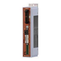
IAI ACON-CB series Instruction Manual (380 pages)
Brand:
IAI
| Category:
Controller
| Size: 12 MB
Table of Contents
Please Read before Use
3
Table of Contents
5
Conformance with Applicable Standards/Regulations, Etc
9
Safety Guide ꞏꞏꞏꞏꞏꞏꞏꞏꞏꞏꞏꞏꞏꞏꞏꞏꞏꞏꞏꞏꞏꞏꞏꞏꞏꞏꞏꞏꞏꞏꞏꞏꞏꞏꞏꞏꞏꞏꞏꞏꞏꞏꞏꞏꞏꞏꞏꞏꞏꞏꞏꞏꞏꞏꞏꞏꞏꞏꞏꞏꞏꞏꞏꞏꞏꞏꞏꞏꞏꞏꞏꞏꞏꞏꞏꞏꞏꞏꞏꞏꞏꞏ Intro-1
11
Storage and Preservation
12
Installation and Start
12
Operation Description
15
Automatic Operation
15
Alert Indication
17
Precautions for Handling ꞏꞏꞏꞏꞏꞏꞏꞏꞏꞏꞏꞏꞏꞏꞏꞏꞏꞏꞏꞏꞏꞏꞏꞏꞏꞏꞏꞏꞏꞏꞏꞏꞏꞏꞏꞏꞏꞏꞏꞏꞏꞏꞏꞏꞏꞏꞏꞏꞏꞏꞏꞏꞏꞏꞏꞏꞏꞏꞏꞏꞏꞏꞏꞏꞏꞏꞏ Intro-8
18
Precautions for PC Connection to Controller
23
Grounded at Positive Terminal of 24V DC Power Supply ꞏꞏꞏꞏꞏꞏꞏꞏꞏꞏꞏꞏꞏꞏꞏꞏꞏꞏꞏꞏꞏꞏꞏꞏꞏꞏꞏꞏ Intro-13
23
International Standard Compliance ꞏꞏꞏꞏꞏꞏꞏꞏꞏꞏꞏꞏꞏꞏꞏꞏꞏꞏꞏꞏꞏꞏꞏꞏꞏꞏꞏꞏꞏꞏꞏꞏꞏꞏꞏꞏꞏꞏꞏꞏꞏꞏꞏꞏꞏꞏꞏꞏꞏꞏꞏꞏꞏꞏ Intro-14
24
Actuator Coordinate System ꞏꞏꞏꞏꞏꞏꞏꞏꞏꞏꞏꞏꞏꞏꞏꞏꞏꞏꞏꞏꞏꞏꞏꞏꞏꞏꞏꞏꞏꞏꞏꞏꞏꞏꞏꞏꞏꞏꞏꞏꞏꞏꞏꞏꞏꞏꞏꞏꞏꞏꞏꞏꞏꞏꞏꞏꞏꞏꞏꞏꞏꞏ Intro-15
25
Chapter 1 Controller Overview
27
Overview
29
System Configuration
30
Name for each Parts and Their Functions
31
Operation Status
34
Power Supply Connector
36
Starting Procedures
37
Product Check
43
Parts
43
Teaching Tool
44
How to Read the Model Plate
45
How to Read the Model
46
Operation Modes and Functions
48
Operation Mode of Controller
48
Positioner Mode
49
Pulse Train Control Mode
51
Field Network Operation Modes and Features
52
List of Basic Specifications
54
External View
56
For Battery-Less Absolute/Incremental Screw-Fixed Type
56
For Battery-Less Absolute/Incremental DIN Rail-Fixed Type
57
Simple Absolute Screw-Fixed Type
58
For Simple Absolute DIN Rail-Fixed Type
59
For Absolute Screw-Fixed Type
60
For Absolute DIN Rail-Fixed Type
61
Absolute Battery Unit (Option for Simple Absolute Type)
62
I/O Specifications
63
PIO Input and Output Interface
63
Pulse Train Input Output Interface
64
Options
65
Pulse Converter (Model: AK-04)
65
Specification
65
Absolute Battery • Absolute Battery Unit
66
Simple Absolute Type
66
Specifications
66
Installation and Storage Environment
69
Installation Environment
69
Storage and Preservation Environment
69
Noise Elimination and Mounting Method
70
Noise Elimination
70
Installation and Mounting
71
Wiring Method
75
Wiring
75
Power Supply Connector (for Power Supply and Emergency Stop)
75
Wiring Layout of Power Supply Connector
84
Connection to Actuator
85
Connection of PIO
87
Connection of Pulse Train Signal
88
SIO Connector Connection
90
Positioner Mode (PIO Control)
92
Wiring Diagram (Connection of Devices)
92
PIO Pattern Selection and PIO Signal
93
PIO Circuit
98
Pulse Train Control Mode
105
Wiring Diagram (Connection of Devices)
105
I/O Signals in Pulse Train Control Mode and each Functions
106
Operation
113
Basic Operation
115
How to Turn on Power
115
Basic Operation Methods
116
Basic Operation
116
Parameter Settings
121
Operation in Positioner Mode
122
PIO Pattern Selection and Main Functions
122
Enable ×︓Disable
122
Operation in Pulse Train Control Mode
122
Overview of Major Functions
123
Set of Position Table
124
Operation
128
Control of Input Signal
133
Operation Ready and Auxiliary Signals (Common to Patterns 0 to 5)
134
Home Return (HOME, HEND, PEND, MOVE)
137
Brake Release (BKRL)
144
Operation with the Position No. Input (PIO Patterns 0 to 3 and 6)
145
Speed Change During the Movement
148
Pitch Feeding (Relative Movement = Incremental Feed)
149
Pressing Operation
151
Tension Operation
155
Multi-Step Pressing
157
Pause and Operation Interruption (*STP, RES, PEND, MOVE)
162
Direct Position Specification (Operation of PIO Pattern 4)
164
Direct Position Specification (Operation of PIO Pattern 5)
179
Home Return (ST0, HEND)
179
Features of LS Signals (LS0 to 2)
183
Operation in Pulse Train Control Mode
189
Function Name
190
I/O Signal Controls
191
Operation Ready and Auxiliary Signals
192
Pulse Train Input Operation
202
Settings of Basic Parameters Required for Operation
206
Electronic Gear Setting
206
Format Settings of Command Pulse Train
208
Pulse Train Datum Position (Parameter No. 167)
208
Parameter Settings Required for Advanced Operations
209
Position Command Primary Filter Time Constant
209
Torque Limit
209
Clearing Deviation During Servo off or Alarm Stop
210
Pulse Count Direction
211
Operation of Field Network Type
212
Absolute Reset
213
How to Perform Absolute Reset
214
Absolute Battery Charge
219
Various Functions
221
Vibration Suppress Control Function (ACON-CB Dedicated Function)
221
Overview
223
Setting Procedure
226
Settings of Parameters for Vibration Suppress Control
227
Setting of Position Data
229
Power-Saving Function
230
AUTO Servo off Function
230
Positioning Operation
233
Detail Explanation of Parameters
235
Adjustment of the ACON
235
I/O Parameter List
238
Parameter List
239
Detail Explanation of Parameters
244
Input Range
247
Servo Adjustment
282
Maintenance and Inspection
287
Periodic Inspection
289
Periodic Inspection Items
290
Inspection Details
291
Requests When Replacing Units
292
Consumable Parts
293
Component Replacement
294
Replacement of Absolute Battery
294
For the Type to Attach Battery to Controller Side
294
When Using Absolute Battery Unit
295
Preventive Maintenance Function
296
Maintenance Information
296
Predictive Maintenance Function
299
Overload Warning
299
Troubleshooting
301
Action to be Taken Upon Occurrence of Problem
303
Fault Diagnosis
305
Impossible Operation of Controller
305
Possible Cause
307
Positioning and Speed of Poor Precision (Incorrect Operation)
309
Generation of Noise And/Or Vibration
311
Impossible Communication
312
About Alarms
313
Simple Alarm Codes
313
Alarm Level
315
Alarm Details
316
Alarm Name
323
Way to Set Multiple Controllers with 1 Teaching Tool
331
Connecting Example
332
Detailed Connection Diagram of Communication Lines
333
Axis No. Setting
334
Handling of E-CON Connector (How to Connect)
335
SIO Converter
336
Communications Cable
338
External Dimension
338
Conformity to Safety Category
339
System Configuration
339
Wiring and Setting of Safety Circuit
340
Examples of Safety Circuits
342
TP Adapter and Accessories
348
Example of Basic Positioning Sequence (PIO Pattern 0 to 3)
351
I/O Assignment
351
Ladder Sequence
352
List of Specifications of Connectable Actuators
362
Warranty Period
373
Scope of the Warranty
373
Honoring the Warranty
373
Limited Liability
374
Conformance with Applicable Standards/Regulations, Etc., and Application Conditions
374
Other Items Excluded from Warranty
374
Revision History
375
Revision Date
377
Advertisement
IAI ACON-CB series First Step Manual (5 pages)
Brand:
IAI
| Category:
Industrial Equipment
| Size: 1 MB
Table of Contents
1. Parts
1
2. Teaching Tool (to be Purchased Separately)
1
3. Instruction Manuals Related to this Product, Which Are Contained in the Instruction Manual (DVD).
1
4. How to Read the Model Plate
1
5. How to Read the Model of the Controller
1
Installation Environment
2
Installation and Noise Elimination
2
ACON, DCON List of Specifications
2
Connection Diagram
3
PC Software (to be Purchased Separately)
3
4. Heat Radiation and Installation
3
Power Supply and Emergency Stop Circuit
3
I/O Signal Explanation of I/O Signal Functions
3
Signal Assignments in each Mode
4
PIO Input and Output Interface
4
Operation in Pulse Train Control Mode (Function for PLN and PLP Types Only)
4
Loadcell (PCON-CBP/CGBP Dedicated Option)
4
Starting Procedures
5
Action to Take When Error Occurred
5
IAI ACON-CB series First Step Manual (5 pages)
Field Network Controllers
Brand:
IAI
| Category:
Controller
| Size: 1 MB
Table of Contents
1. Parts
1
2. Teaching Tool (to be Purchased Separately)
1
3. Instruction Manuals Related to this Product, Which Are Contained in the Instruction Manual (DVD).
1
4. How to Read the Model Plate
1
5. How to Read the Model of the Controller
1
Installation Environment
2
Installation and Noise Elimination
2
ACON, DCON List of Specifications
2
Connection Diagram
3
PC Software (to be Purchased Separately)
3
4. Heat Radiation and Installation
3
Power Supply and Emergency Stop Circuit
3
I/O Signal Explanation of I/O Signal Functions
3
Starting Procedures
4
Signal Assignment for each Mode
4
Operation in Pulse Train Control Mode (Function for PLN and PLP Types Only)
4
Action to Take When Error Occurred
5
Advertisement
Advertisement
Related Products
IAI ACON-CB
IAI ACON-C
IAI ACON-CG
IAI acon
IAI ACON-CA
IAI ACON-CGB
IAI ACON-CYB
IAI ACON-PLB
IAI ACON-POB
IAI ASEP
IAI Categories
Controller
Digital Camera
Gateway
Security Camera
Industrial Equipment
More IAI Manuals
Login
Sign In
OR
Sign in with Facebook
Sign in with Google
Upload manual
Upload from disk
Upload from URL