Sign In
Upload
Manuals
Brands
Hytera Manuals
Radio
MD78XG
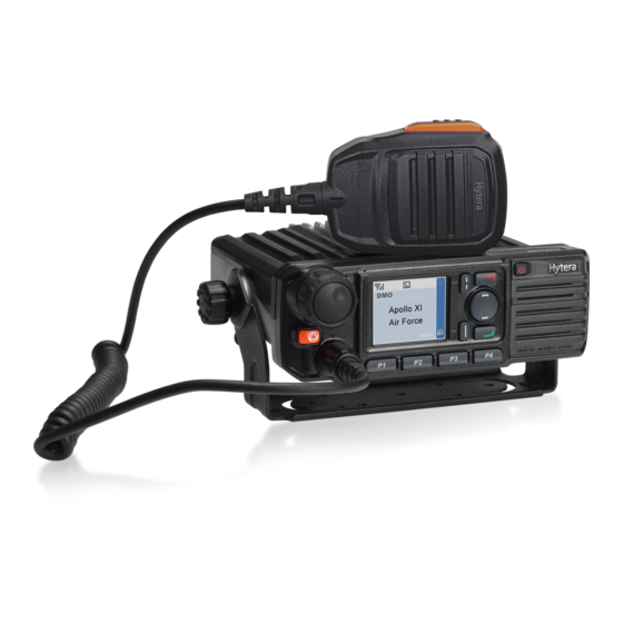
Hytera MD78XG Manuals
Manuals and User Guides for Hytera MD78XG. We have
6
Hytera MD78XG manuals available for free PDF download: Service Manual, Manual, User Manual, Quick Reference Manual
Hytera MD78XG Service Manual (638 pages)
Brand:
Hytera
| Category:
Radio
| Size: 27 MB
Table of Contents
Copyright Information
3
Table of Contents
4
Documentation Information
14
1 Introduction
15
2 Product Controls
16
3 Front Panel Section
18
Figure 3-1 Diagram of Front Panel
18
4 Baseband Section
20
Power Section
20
Figure 4-1 Diagram of Power Distribution
20
Power On/Off
21
Power On/Off Key
21
Ignition Signal
21
Emergency
21
Power-Up Process
22
Clock
22
Input Clock
22
Figure 4-2 Diagram of Clock Distribution
22
Output Clock
23
Interface Distribution
23
SPI Interface
23
MCSI Interface
23
MICROWIRE Interface
23
Figure 4-3 Diagram of SPI Interface
23
Figure 4-4 Diagram of MCSI Interface
23
Figure 4-5 Diagram of MICROWIRE Interface
23
SSI Interface
24
Figure 4-6 Diagram of SSI Interface
24
USB Interface
25
UART Interface
25
Mobile Accessory Connector (MAC)
25
Figure 4-7 Diagram of USB Interface
25
Figure 4-8 Diagram of UART Interface
25
Option Board Interface
26
Table 4-1 Description on Option Board Interface
27
Audio Section
28
RX Audio Circuit
28
Figure 4-9 Diagram of Audio Section
28
TX Audio Circuit
29
Troubleshooting Flow Chart
30
PCB Difference
31
Watchdog Circuit
31
Figure 4-10 Watchdog Circuit
31
5 GPS Circuit
32
Circuit Description
32
Figure 5-1 Diagram of GPS Circuit
32
Schematic Diagram
33
Parts List
33
Figure 5-2 GPS Schematic Diagram
33
Troubleshooting Flow Chart
34
6 Tuning Description
35
7 Interface Definition
36
Table 7-1 J404: to Front Panel Jack
37
Table 7-2 J4: to Aviation Jack of Front Panel
38
Table 7-3 J2: to LCD Display Jack
39
Table 7-4 J403: to Accessory Pin Jack
41
8 UHF1 (400-470Mhz 25W) Information
42
Transmitter Circuit
42
Power Amplifier
42
TX Buffer Amplifier
42
Figure 8-1 Diagram of Transmitter Circuit
42
Pre-Driver Power Amplifier
43
Driver Power Amplifier
43
Final Power Amplifier
43
Antenna Switch
43
Low-Pass Filter
43
Directional Coupler
43
Output Power Control
44
Thermal and Over-Voltage Protections
44
Pressure Pad Switch
44
Receiver Circuit
44
Receiver Front-End
45
Figure 8-2 Diagram of Receiver Circuit
45
Receiver Back-End
46
Frequency Generation Unit (FGU)
46
PLL Synthesizer
46
Figure 8-3 Diagram of if Processor
46
Reference Oscillator
47
Pll IC
47
Vco
47
Figure 8-4 Diagram of PLL IC
47
Figure 8-5 Diagram of VCO
48
PCB View
49
Block Diagram
53
Schematic Diagram
56
Parts List
70
Troubleshooting Flow Chart
108
9 UHF1 (400-470Mhz 45W) Information
114
Transmitter Circuit
114
Power Amplifier
114
TX Buffer Amplifier
114
Figure 9-1 Diagram of Transmitter Circuit
114
Pre-Driver Power Amplifier
115
Driver Power Amplifier
115
Final Power Amplifier
115
Antenna Switch
115
Low-Pass Filter
115
Directional Coupler
116
Output Power Control
116
Thermal and Over-Voltage Protections
116
Pressure Pad Switch
116
Receiver Circuit
116
Receiver Front-End
117
Figure 9-2 Diagram of Receiver Circuit
117
Receiver Back-End
118
Frequency Generation Unit (FGU)
118
PLL Synthesizer
118
Figure 9-3 Diagram of if Processor
118
Reference Oscillator
119
Pll IC
119
Figure 9-4 Diagram of PLL IC
119
Vco
120
Figure 9-5 Diagram of VCO
120
PCB View
121
Block Diagram
125
Schematic Diagram
128
Parts List
142
Troubleshooting Flow Chart
180
10 UHF2 (450-520Mhz 25W) Information
186
Transmitter Circuit
186
Power Amplifier
186
TX Buffer Amplifier
186
Figure 10-1 Diagram of Transmitter Circuit
186
Pre-Driver Power Amplifier
187
Driver Power Amplifier
187
Final Power Amplifier
187
Antenna Switch
187
Low-Pass Filter
187
Directional Coupler
188
Output Power Control
188
Thermal and Over-Voltage Protections
188
Pressure Pad Switch
188
Receiver Circuit
188
Receiver Front-End
189
Figure 10-2 Diagram of Receiver Circuit
189
Receiver Back-End
190
Frequency Generation Unit (FGU)
190
PLL Synthesizer
190
Figure 10-3 Diagram of if Processor
190
Reference Oscillator
191
Pll IC
191
Vco
191
Figure 10-4 Diagram of PLL IC
191
Figure 10-5 Diagram of VCO
192
PCB View
193
Block Diagram
197
Schematic Diagram
200
Parts List
214
Troubleshooting Flow Chart
252
11 UHF2 (450-520Mhz 45W) Information
258
Transmitter Circuit
258
Power Amplifier
258
TX Buffer Amplifier
258
Figure 11-1 Diagram of Transmitter Circuit
258
Pre-Driver Power Amplifier
259
Driver Power Amplifier
259
Final Power Amplifier
259
Antenna Switch
259
Low-Pass Filter
259
Directional Coupler
260
Output Power Control
260
Thermal and Over-Voltage Protections
260
Pressure Pad Switch
260
Receiver Circuit
260
Receiver Front-End
261
Figure 11-2 Diagram of Receiver Circuit
261
Receiver Back-End
262
Frequency Generation Unit (FGU)
262
PLL Synthesizer
262
Figure 11-3 Diagram of if Processor
262
Reference Oscillator
263
Pll IC
263
Figure 11-4 Diagram of PLL IC
263
Vco
264
Figure 11-5 Diagram of VCO
264
PCB View
265
Block Diagram
269
Schematic Diagram
272
Parts List
286
Troubleshooting Flow Chart
325
12 UHF3 (350-400Mhz 25W) Information
331
Transmitter Circuit
331
Power Amplifier
331
TX Buffer Amplifier
331
Figure 12-1 Diagram of Transmitter Circuit
331
Pre-Driver Power Amplifier
332
Driver Power Amplifier
332
Final Power Amplifier
332
Antenna Switch
332
Low-Pass Filter
332
Directional Coupler
333
Output Power Control
333
Thermal and Over-Voltage Protections
333
Pressure Pad Switch
333
Receiver Circuit
333
Receiver Front-End
334
Figure 12-2 Diagram of Receiver Circuit
334
Receiver Back-End
335
Frequency Generation Unit (FGU)
335
PLL Synthesizer
335
Figure 12-3 Diagram of if Processor
335
Reference Oscillator
336
Pll IC
336
Figure 12-4 Diagram of PLL IC
336
Vco
337
Figure 12-5 Diagram of VCO
337
PCB View
338
Block Diagram
342
Schematic Diagram
345
Parts List
359
Troubleshooting Flow Chart
398
13 UHF3 (350-400Mhz 45W) Information
404
Transmitter Circuit
404
Power Amplifier
404
TX Buffer Amplifier
404
Figure 13-1 Diagram of Transmitter Circuit
404
Pre-Driver Power Amplifier
405
Driver Power Amplifier
405
Final Power Amplifier
405
Antenna Switch
405
Low-Pass Filter
405
Directional Coupler
406
Output Power Control
406
Thermal and Over-Voltage Protections
406
Pressure Pad Switch
406
Receiver Circuit
406
Receiver Front-End
407
Figure 13-2 Diagram of Receiver Circuit
407
Receiver Back-End
408
Frequency Generation Unit (FGU)
408
PLL Synthesizer
408
Figure 13-3 Diagram of if Processor
408
Reference Oscillator
409
Pll IC
409
Figure 13-4 Diagram of PLL IC
409
Vco
410
Figure 13-5 Diagram of VCO
410
PCB View
411
Block Diagram
415
Schematic Diagram
418
Parts List
432
Troubleshooting Flow Chart
471
14 VHF (136-174Mhz 25W) Information
477
Transmitter Circuit
477
Power Amplifier
477
Pre-Driver Power Amplifier
477
Figure 14-1 Diagram of Transmitter Circuit
477
Driver Power Amplifier
478
Final Power Amplifier
478
Antenna Switch
478
Low-Pass Filter
478
Directional Coupler
478
Output Power Control
479
Thermal and Over-Voltage Protections
479
Pressure Pad Switch
479
Receiver Circuit
479
Receiver Front-End
480
Figure 14-2 Diagram of Receiver Circuit
480
Receiver Back-End
481
Frequency Generation Unit (FGU)
481
PLL Synthesizer
481
Figure 14-3 Diagram of if Processor
481
Reference Oscillator
482
Pll IC
482
Figure 14-4 Diagram of PLL IC
482
Vco
483
Figure 14-5 Diagram of VCO
483
PCB View
484
Block Diagram
488
Schematic Diagram
491
Parts List
505
Troubleshooting Flow Chart
545
15 VHF (136-174Mhz 50W) Information
551
Transmitter Circuit
551
Power Amplifier
551
Pre-Driver Power Amplifier
551
Driver Power Amplifier
551
Figure 15-1 Diagram of Transmitter Circuit
551
Final Power Amplifier
552
Antenna Switch
552
Low-Pass Filter
552
Directional Coupler
552
Output Power Control
553
Thermal and Over-Voltage Protections
553
Pressure Pad Switch
553
Receiver Circuit
553
Figure 15-2 Diagram of Receiver Circuit
553
Figure 15-3 Diagram of if Processor
554
Receiver Back-End
554
Receiver Front-End
554
Frequency Generation Unit (FGU)
555
PLL Synthesizer
555
Reference Oscillator
555
Pll IC
555
Vco
556
Figure 15-4 Diagram of PLL IC
556
Figure 15-5 Diagram of VCO
557
PCB View
558
Block Diagram
562
Schematic Diagram
565
Parts List
579
Troubleshooting Flow Chart
620
16 Disassembly and Assembly
626
Disassembly
626
Assembly
627
17 Exploded View
629
18 Packing Guide
633
19 Specifications
634
Advertisement
Hytera MD78XG Service Manual (595 pages)
DMR MOBILE RADIO
Brand:
Hytera
| Category:
Radio
| Size: 27 MB
Table of Contents
Preface
2
Table of Contents
3
1 Revision History
7
2 Copyright Information
8
3 Disclaimer
9
4 Product Overview
10
Intended User
10
5 Product Controls
11
Front Panel
11
Rear Panel
12
Power Supply
13
Keys
13
LCD Display
13
Diagram of Front Panel
13
Leds and Backlight
14
MMC
14
Audio Output
14
Volume Control
14
7 Baseband Section
15
Power Section
15
Power On/Off
16
Power On/Off Key
16
Ignition Signal
16
Emergency
16
Clock
17
Interface Distribution
17
Input Clock
17
Serial Peripheral Interface (SPI)
17
MICROWIRE Interface
18
Serial Synchronous Interface (SSI)
18
USB Interface
19
UART Interface
19
Diagram of SSI Interface
19
Diagram of USB Interface
19
Mobile Accessory Connector (MAC)
20
Option Board Interface
20
Diagram of UART Interface
20
Audio Section
22
RX Audio Circuit
22
TX Audio Circuit
22
Diagram of Audio Section
22
Troubleshooting Flow Chart for Control Circuit
24
PCB Difference
25
Watchdog Circuit
25
8 GPS Circuit
26
Circuit Description
26
Schematic Diagram
26
Diagram of GPS Circuit
26
Parts List
27
Troubleshooting Flow Chart
28
9 Tuning Description
29
10 Interface Definition
30
11 UHF1 (400-470Mhz 25W) Information
33
Transmitter Circuit
33
Power Amplifier
33
TX Buffer Amplifier
33
Driver Power Amplifier
34
Final Power Amplifier
34
Antenna Switch
34
Low-Pass Filter
34
Output Power Control
35
Thermal and Over-Voltage Protections
35
Pressure Pad Switch
35
Receiver Circuit
35
Receiver Back-End
36
Frequency Generation Unit (FGU)
36
PLL Synthesizer
36
Diagram of if Processor
36
Reference Oscillator
37
Pll IC
37
Vco
37
Diagram of PLL IC
37
Diagram of VCO
38
MD78X/MD78XG PCB View (Front Panel)
39
Top Layer
39
Bottom Layer
40
MD78X/MD78XG PCB View (Main Board)
41
MD78X/MD78XG Block Diagram (Power Section)
43
BB Schematic Block Diagram
45
MD78X/MD78XG Schematic Diagram
46
Parts List
60
Troubleshooting Flow Chart
95
Description of Normal Situations
96
Fgu
99
12 UHF1 (400-470Mhz 45W) Information
101
Transmitter Circuit
101
Receiver Circuit
103
Frequency Generation Unit (FGU)
104
PCB View
107
Block Diagram
111
Schematic Diagram
114
Parts List
128
Troubleshooting Flow Chart
163
13 UHF2 (450-520Mhz 25W) Information
169
Transmitter Circuit
169
Receiver Circuit
171
Frequency Generation Unit (FGU)
172
PCB View
175
Block Diagram
179
Schematic Diagram
182
Parts List
196
Troubleshooting Flow Chart
232
14 UHF2 (450-520Mhz 45W) Information
238
Transmitter Circuit
238
Receiver Circuit
240
Frequency Generation Unit (FGU)
241
PCB View
244
Block Diagram
248
Schematic Diagram
251
Parts List
265
Troubleshooting Flow Chart
301
15 UHF3 (350-400Mhz 25W) Information
307
Transmitter Circuit
307
Receiver Circuit
309
Frequency Generation Unit (FGU)
310
PCB View
313
Block Diagram
317
Schematic Diagram
320
Parts List
334
Troubleshooting Flow Chart
370
16 UHF3 (350-400Mhz 45W) Information
376
Transmitter Circuit
376
Receiver Circuit
378
Frequency Generation Unit (FGU)
379
PCB View
382
Block Diagram
386
Schematic Diagram
389
Parts List
403
Troubleshooting Flow Chart
439
17 VHF (136-174Mhz 25W) Information
445
Transmitter Circuit
445
Receiver Circuit
447
Frequency Generation Unit (FGU)
448
PCB View
451
Block Diagram
455
Schematic Diagram
458
Parts List
472
Troubleshooting Flow Chart
509
18 VHF (136-174Mhz 50W) Information
515
Transmitter Circuit
515
Receiver Circuit
517
Frequency Generation Unit (FGU)
518
PCB View
521
Block Diagram
525
Schematic Diagram
528
Parts List
542
Troubleshooting Flow Chart
579
19 Disassembly and Assembly
585
20 Exploded View
588
21 Packing Guide
591
22 Specifications
592
Hytera MD78XG Service Manual (519 pages)
DIGITAL MOBILE RADIO
Brand:
Hytera
| Category:
Radio
| Size: 25 MB
Table of Contents
Uhf1 (400-470 Mhz)
6
Table of Contents
6
Product Controls
8
Disassembly and Reassembly
10
Disassembling the Radio
10
Reassembling the Radio
11
Exploded View and Packing Guide
12
Exploded View
12
Packing Guide
14
Specifications and Blind Spot
15
Specifications
15
Blind Spot
18
Circuit Description
19
Front Panel
19
Baseband
21
Power Supply Module
21
Control Module
22
Audio Module
28
PCB Difference
29
RF Section
30
Transmitter Circuit
30
Receiver Circuit
33
FGU Circuit
34
GPS Circuit Section
36
Troubleshooting Flow Chart
37
Control Circuit
37
GPS Circuit
38
TX Circuit
39
RX Circuit
40
Frequency Generation Unit (FGU)
42
Interface Definition
44
10-Pin Connector
44
DB26 Accessory Interface
46
Other Interfaces
49
Tuning Description
57
Required Test Instruments
57
Tuning Procedures
57
Tuning the Radio
57
Testing the Radio
60
PCB View
62
Block Diagram
66
Schematic Diagram
69
Parts List
83
Front Panel
83
GPS Circuit
84
Main Board (25 W)
84
Main Board (45 W)
97
Uhf2 (450-520 Mhz)
112
Product Controls
114
Disassembling the Radio
116
Disassembly and Reassembly
116
Reassembling the Radio
117
Exploded View
118
Exploded View and Packing Guide
118
Packing Guide
120
Specifications
121
Specifications and Blind Spot
121
Blind Spot
124
Circuit Description
125
Front Panel
125
Baseband
127
Power Supply Module
127
Control Module
128
Audio Module
134
PCB Difference
135
RF Section
136
Transmitter Circuit
136
Receiver Circuit
139
FGU Circuit
140
GPS Circuit Section
142
Control Circuit
143
Troubleshooting Flow Chart
143
GPS Circuit
144
TX Circuit
145
RX Circuit
146
Frequency Generation Unit (FGU)
148
10-Pin Connector
150
Interface Definition
150
DB26 Accessory Interface
152
Other Interfaces
155
Required Test Instruments
162
Tuning Description
162
Tuning Procedures
162
Tuning the Radio
162
Testing the Radio
165
PCB View
167
Block Diagram
171
Schematic Diagram
174
Front Panel
188
Parts List
188
GPS Circuit
189
Main Board (25 W)
189
Main Board (45 W)
202
Uhf3 (350-400 Mhz)
217
Product Controls
219
Disassembling the Radio
221
Disassembly and Reassembly
221
Reassembling the Radio
222
Exploded View
223
Exploded View and Packing Guide
223
Packing Guide
225
Specifications
226
Specifications and Blind Spot
226
Blind Spot
229
Circuit Description
230
Front Panel
230
Baseband
232
Power Supply Module
232
Control Module
233
Audio Module
239
PCB Difference
240
RF Section
241
Transmitter Circuit
241
Receiver Circuit
244
FGU Circuit
245
GPS Circuit Section
247
Control Circuit
248
Troubleshooting Flow Chart
248
GPS Circuit
249
TX Circuit
250
RX Circuit
251
Frequency Generation Unit (FGU)
253
10-Pin Connector
255
Interface Definition
255
DB26 Accessory Interface
257
Other Interfaces
260
Required Test Instruments
267
Tuning Description
267
Tuning Procedures
267
Tuning the Radio
267
Testing the Radio
270
PCB View
272
Schematic Diagram
279
Front Panel
293
Parts List
293
GPS Circuit
294
Main Board (25 W)
294
Main Board (45 W)
294
Uhf5 (806-941 Mhz)
322
Product Controls
324
Disassembling the Radio
326
Disassembly and Reassembly
326
Reassembling the Radio
327
Exploded View
328
Exploded View and Packing Guide
328
Packing Guide
330
Specifications
331
Specifications and Blind Spot
331
Blind Spot
334
Circuit Description
335
Front Panel
335
Power Supply Module
337
Control Module
338
Audio Module
345
RF Section
346
Transmitter Circuit
346
Receiver Circuit
348
FGU Circuit
349
GPS Circuit Section
351
Control Circuit
352
Troubleshooting Flow Chart
352
GPS Circuit
353
TX Circuit
354
RX Circuit
355
Frequency Generation Unit (FGU)
356
10-Pin Connector
358
Interface Definition
358
DB26 Accessory Interface
360
Other Interfaces
364
Required Test Instruments
371
Tuning Description
371
Tuning Procedures
371
Tuning the Radio
371
Testing the Radio
374
PCB View
376
Block Diagram
380
Schematic Diagram
383
Front Panel
398
Parts List
398
GPS Circuit
399
Main Board
399
Vhf (136 - 174 Mhz)
415
Product Controls
417
Disassembling the Radio
419
Disassembly and Reassembly
419
Reassembling the Radio
420
Exploded View
421
Exploded View and Packing Guide
421
Packing Guide
423
Specification
424
Specifications and Blind Spot
424
Blind Spot
427
Circuit Description
428
Front Panel
428
Baseband
430
Power Supply Module
430
Control Module
431
Audio Module
437
RF Section
438
Transmitter Circuit
438
Receiver Circuit
441
FGU Circuit
442
GPS Circuit
444
Control Circuit
445
Troubleshooting Flow Chart
445
GPS Circuit
446
TX Circuit
447
RX Circuit
448
Frequency Generation Unit (FGU)
449
10-PIN Connector
451
Interface Definition
451
DB26 Accessory Interface
453
Other Interfaces
457
Required Test Instruments
463
Tuning Description
463
Tuning Procedures
463
Tuning the Radio
463
Testing the Radio
466
PCB View
468
Block Diagram
472
Schematic Diagram
475
Front Panel
489
Parts List
489
GPS Circuit
490
Main Board (25W)
490
Main Board (50W)
504
Advertisement
Hytera MD78XG Manual (36 pages)
Digital Mobile Radio
Brand:
Hytera
| Category:
Radio
| Size: 1 MB
Table of Contents
Copyright Information
2
Term Explanation
2
Fcc Regulations
3
Table of Contents
5
Checking Items in the Package
6
Product Overview
7
Front Panel
7
Rear Panel
7
Programmable Keys
8
Installation
9
Instructions
9
Installation Tools
9
Installation Steps
9
Status Indication
11
LCD Icon
11
LED Indicator
12
Basic Operations
13
Turning the Radio On/Off
13
Adjusting the Volume
13
Selecting a Zone
13
Selecting a Channel
13
Switching the Channel Mode
13
Call
14
Private Call
14
Group Call
14
All Call
15
Calls on Analog Channels
15
Menu Navigation
16
Contact
16
Message
17
Call Logs
18
Scan
18
Zone
19
Settings
19
Accessories
21
Functions and Operations
22
Home Screen
22
Scan
22
Public Address
22
Talk Around
23
Monitor
23
Squelch off
23
Emergency
23
Ignition Sense
27
Scrambler /Encrypt
27
Functions and Operations
27
Busy Channel Lockout
28
Time-Out Timer (TOT)
28
Pseudo Trunking
28
MIC Agc
28
Emergency Footswitch
28
Channel Steering
29
Radio Registration Service
29
GPS Revert
29
Lone Worker
29
Signaling Introduction
30
Hdc1200
30
5-Tone
30
Troubleshooting
32
Care and Cleaning
34
Optional Accessories
35
Appendix
36
Input Method
36
Hytera MD78XG User Manual (28 pages)
Digital Mobile Radio
Brand:
Hytera
| Category:
Radio
| Size: 0 MB
Table of Contents
Fcc Regulations
3
Items in the Package
5
Product Overview
6
Front Panel
6
Rear Panel
7
Programmable Keys
7
Before Use
8
Installation Tools
8
Installation Procedure
8
Status Indication
11
Lcd Icon
11
Led Indicator
12
Menu Navigation
14
Basic Operations
15
Adjusting the Volume
15
Selecting a Zone
16
Selecting a Channel
16
Contact List
17
Private Call
18
Receiving and Responding to a Private Call
19
Group Call
19
Initiating a Group Call
19
Emergency Call
20
Message Service
21
Troubleshooting
22
Care and Cleaning
24
Optional Accessories
25
RF Radiation Safety Warnings and the Following
27
Hytera MD78XG Quick Reference Manual (12 pages)
Brand:
Hytera
| Category:
Portable Radio
| Size: 2 MB
Table of Contents
Programmable Keys
4
Basic Operations
5
Adjusting the Volume
5
Using the Keypad
5
Switching the Operation Mode
5
Status Indications
6
Checking LED Indications
7
Call Services
7
Emergency Call
10
Message Services
10
Viewing Messages
10
Sending Messages
10
Advertisement
Related Products
Hytera MD78X
Hytera MD780
Hytera MD785
Hytera MD785G
Hytera MD78 SERIES
Hytera MD78*G
Hytera MD78Xi
Hytera MD655
Hytera MD656
Hytera MD61X
Hytera Categories
Portable Radio
Radio
Repeater
Two-Way Radio
Touch terminals
More Hytera Manuals
Login
Sign In
OR
Sign in with Facebook
Sign in with Google
Upload manual
Upload from disk
Upload from URL