Sign In
Upload
Manuals
Brands
Hioki Manuals
Measuring Instruments
IM3533
Hioki IM3533 Manuals
Manuals and User Guides for Hioki IM3533. We have
5
Hioki IM3533 manuals available for free PDF download: Instruction Manual, Communication Instruction Manual
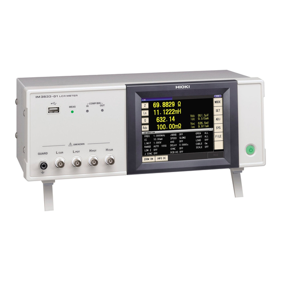
Hioki IM3533 Instruction Manual (400 pages)
LCR
Brand:
Hioki
| Category:
Measuring Instruments
| Size: 13 MB
Table of Contents
Table of Contents
3
Introduction
9
Verifying Package Contents
9
Safety Information
11
Operating Precautions
13
Chapter 1 Overview
17
Product Overview Features
17
Names and Functions of Parts
18
Screen Configuration and Operation
20
Initial Screen
20
Measurement Mode Selection Screen
21
Advanced Settings Screen
22
Compensation Settings Screen
32
System Settings Screen
33
Save Settings Screen
35
Parameter Settings Screen
36
Chapter 2 Measurement Preparations
37
Preparation Flowchart
37
Pre-Operation Inspection
38
Connecting the Power Cord
39
Connecting the Measurement Cables, Probes, or Fixture
40
Connecting a Temperature Probe
41
Connecting an Interface
42
Turning the Power on and off
43
Chapter 3 Measurement Example
45
When LCR Mode
45
When ANALYZER Mode (IM3533-01 Only)
47
When TRANSFORMER Mode
49
Chapter 4 LCR Function
53
About LCR Function
53
Measurement Screen
53
Setting Display Parameters
55
Enlarging Display of Measurement Values
57
Setting Basic Settings of Measurement Conditions
58
Setting the Measurement Frequency
58
Setting the Measurement Signal Level
60
Limiting the Voltage and Current Applied to the Sample (Limit Values)
64
Setting the DC Bias
66
Perform Measurements with User-Defined Timing (Trigger Measurement)
68
Setting the Measurement Range
70
Setting the Method for Determining the Measurement Range (AUTO, HOLD, JUDGE SYNC)
70
Low Z High Accuracy Mode
79
Setting the Measurement Speed
81
Displaying Average Values (Averaging Set)
82
Setting the Delay Time until Measurement Data Is Captured (Trigger Delay)
84
Applying the Signal to the Sample During Measurement Only (Trigger Synchronous Output Function)
85
Setting DC Resistance Measurement
88
Configuring the Temperature Correction Function
89
Setting the DC Measurement Delay Time (DC Delay)
91
Setting the Offset Measurement Delay Time (Adjustment Delay)
93
Setting the Line Frequency
95
Setting the Measurement Range
96
Setting the Method for Determining the Measurement Range (HOLD, AUTO, JUDGE SYNC)
96
Low Z High Accuracy Mode
104
Setting the Measurement Speed
106
Displaying Average Values (Average Set)
107
Judging Measurement Results
108
Judging with Upper and Lower Limit Values (Comparator Measurement Mode)
110
Setting the Upper or Lower Limit Value as an Absolute Value (ABS) (Absolute Value Mode)
112
Setting the Upper or Lower Limit Value as a Percentage (%) Relative to a Reference Value (Percentage Mode)
113
Setting Upper and Lower Limit Values as (%) Values Relative to the Offset from the Reference Value (Deviation Percentage Mode)
115
Classifying Measurement Results (bin Measurement)
117
Setting the Upper or Lower Limit Value as an Absolute Value (ABS) (Absolute Value Mode)
119
Setting the Upper or Lower Limit Value as a Percentage (%) Relative to a Reference Value (Percentage Mode)
122
Mode)
122
The Reference Value (Deviation Percentage Mode)
125
Setting Application Settings
128
Setting Measurement Conditions for
128
(Range Synchronization Function)
128
Setting the Detection Signal Waveform Averaging Count (Waveform Averaging Function)
136
Detecting OPEN During 2-Terminal Measurement (HIGH-Z Reject Function)
138
Checking Contact Defects and the Contact State (Contact Check Function)
140
Setting the Delay Time from the Output of Comparator and bin Judgment Results until Output of EOM (LOW) and Resetting Judgment Results
142
Enabling Trigger Input for During Measurement and Setting the Valid Edge of Trigger Input
144
Setting the EOM Output Method
145
Saving Measurement Results (Memory Function)
146
Setting the Number of Display Digits
148
10Setting the LCD to ON/OFF
150
11Setting Operation Sounds (Beep Sounds)
151
12Disabling Key Operation (Key-Lock Function)
152
13Initializing (System Reset)
155
Chapter 5 ANALYZER Function (IM3533-01)
157
About ANALYZER Function
157
Measurement Screen
157
Setting Basic Settings of Measurement
158
Setting the Measurement Parameter
158
Setting the Trigger
159
Setting the Display Timing
160
Setting the Trigger Delay
161
Setting Sweep Points
163
Setting the Measurement Signal Level
166
Setting the Measurement Range
168
Setting the Method for Determining the Measurement Range (AUTO, HOLD)
168
Low Z High Accuracy Mode
172
Setting the Measurement Speed
174
Displaying as Average Values (Average Set)
175
10Setting the Point Delay
176
11Setting the DC Bias
177
Application Settings
179
Applying the Signal to the Sample Only During Measurement (Trigger Synchronous Output Function)
179
Setting the Detection Signal Waveform Averaging Count (Waveform Averaging Function)
181
Detecting OPEN During 2-Terminal Measurement (HIGH-Z Reject Function)
183
Checking Contact Defects and the Contact State (Contact Check Function)
185
Saving Measurement Results (Memory Function)
187
AUTO Range Limit Function
190
Setting the LCD to ON/OFF
192
Setting Operation Sounds (Beep Sounds)
193
Disabling Key Operation (Key-Lock Function)
194
10Enabling Trigger Input for During Mea- Surement and Setting the Valid Edge of Trigger Input
197
11Setting the EOM Output Method
198
12Initializing (System Reset)
199
Chapter 6 TRANSFORMER Function
201
About TRANSFORMER Function
201
Measurement Screen
201
Measurement Methods
202
Setting the Measurement Parameter
204
Setting Calculation Parameters
205
Setting Basic Settings of Measurement Conditions
206
Judging with Upper and Lower Limit Values (Comparator Measurement Mode)
207
Setting the Upper or Lower Limit Value as an Absolute Value (ABS) (Absolute Value Mode)
210
Setting the Upper or Lower Limit Value as a Percentage (%) Relative to a Reference Value (Percentage Mode)
211
Setting Upper and Lower Limit Values as (%) Values Relative to the Offset from the Reference Value (Deviation Percentage Mode)
213
Setting Application Settings
215
Chapter 7 CONTINUOUS Measurement Function
217
About CONTINUOUS Measurement Function
217
Measurement Screen
217
Configuring CONTINUOUS Measurement Basic Settings
218
Performing CONTINUOUS Measurement
219
Checking CONTINUOUS Measurement Results
220
Configuring CONTINUOUS Measurement Application Settings
221
Setting the Display Timing
221
Setting the LCD to ON/OFF
222
Chapter 8 Error
223
Compensation
223
Setting Open Circuit Compensation
223
All Compensation
224
Spot Compensation
228
Short Circuit Compensation
232
All Compensation
234
Spot Compensation
236
Compensating Values to Match Reference Values (Load Compensation)
240
Compensating Measurement Cable Errors (Cable Length Compensation)
253
Calculating Values (Scaling)
254
Chapter 9 Saving and Loading Panel Information
257
Saving Measurement Conditions (Panel Save Function)
259
Loading Measurement Conditions (Panel Load Function)
264
Changing a Panel Name
266
Deleting a Panel
268
Chapter 10 Setting the SYSTEM
271
Setting the Interface
271
Checking the Version of the Instrument
272
Self Checks (Self Diagnosis)
273
Setting the Date and Time
280
Drive
281
Chapter 11 Using USB Flash
282
Inserting and Removing USB Flash Drive
282
About the File Operation Screen
283
About the File Save Setting Screen
284
Saving Measurement Data
285
Saving a Copy of the Screen
295
Checking the Contents of Files
298
Changing the Save Folder
299
Saving Instrument Settings
301
Saving Instrument Settings
303
Saving All Settings of Instrument (ALL SAVE Function)
303
Loading Instrument Settings
305
Loading All Settings Saved on a USB Flash Drive
308
(ALL LOAD Function)
308
File and Folder Operations
310
Formatting a USB Flash Drive
310
Deleting Files and Folders
312
Displaying the USB Flash Drive Information
315
Chapter 12 External Control309
317
External Input/Output Connector and Signals
317
Connector Type and Signal Pinouts
318
Signal Function Details
324
Timing Chart
326
1LCR Mode
326
ANALYZER Mode (IM3533-01 Only)
329
3TRANSFORMER Mode
330
4CONTINUOUS Measurement Mode
331
Internal Circuitry
333
Electrical Specifications
334
Internal Circuitry
335
Connection Examples
335
External I/O Settings
336
Setting Reset of Judgment Results
336
Enabling Trigger Input for During Measurement
336
Setting Valid Edge of Trigger Input
336
External Control Q&A
337
Measurement Using a Computer
337
Chapter 13 Printing
339
Connecting the Printer
339
Connecting the Printer to the Instrument
340
Instrument and Printer Settings
341
Make Instrument Settings
341
Printing
342
Chapter 14 Specifications
345
General Specifications
345
Basic Specifications
346
Measurement Range and Accuracy
350
About Measurement Times and Measurement Speed
358
Chapter 15 Maintenance and Service
361
Inspection, Repair and Cleaning
361
Troubleshooting
363
Error Display
368
Discarding the Instrument
370
Appendix
371
Appendix1 Measurement Parameters and Calculation Formula
372
Appendix2 Measurement of High Impedance Components
373
Appendix3 Measurement of In-Circuit Compo- Nents
374
Appendix4 Countermeasures against Incorpo- Ration of External Noise
375
Appendix4.1 Countermeasures against Incorporation of Noise from the Power Line
375
Appendix5 Supplying DC Bias
377
Appendix5.1How to Supply a DC Bias Voltage
377
Appendix5.2How to Supply a DC Bias Current
379
Appendix6 the Residual Charge Protection Function
380
Appendix7 Series Equivalent Circuit Mode and Parallel Equivalent Circuit Mode
381
Appendix8 Open Circuit Compensation and Short Circuit Compensation
382
Appendix9 Temperature Correction Function (TC)
383
Appendix10Rack Mounting
385
Installation Procedure
386
Appendix11Dimensional Diagram
387
Appendix12Initial Settings Table
388
Advertisement
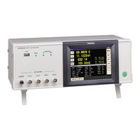
Hioki IM3533 Communication Instruction Manual (74 pages)
Brand:
Hioki
| Category:
Measuring Instruments
| Size: 1 MB
Table of Contents
Table of Contents
3
Introduction
5
Safety Information
5
Chapter 1 Specifications
7
RS-232C Specifications
7
GP-IB Specifications
8
USB Specifications
8
LAN Specifications
8
Chapter 2 Model IM3570/ IM3536 Connection and Setting
9
Overview of Communication
9
RS-232C Connection and Settings
11
Connecting the RS-232C Cable
11
Setting RS-232C
12
GP-IB Connection and Settings
13
USB Settings and Connection
15
USB Settings and Connection
16
LAN Settings and Connection
17
LAN Settings and Connection
22
Remote Mode
23
Chapter 3 Model IM3523 Connection and Setting
25
Overview of Communication
25
USB Settings and Connection
26
USB Settings and Connection
27
GP-IB Connection and Settings (When Connected to the Z3000)
28
Connecting the GP-IB Cable
28
Setting GP-IB
28
RS-232C Connection and Settings (When Connected to the Z3001)
30
Connecting the RS-232C Cable
30
Setting RS-232C
31
LAN Settings and Connection (When Connected to the Z3002)
33
Connecting a LAN Cable
37
Remote Mode
38
Chapter 4 Model IM3533/ IM3533-01/ IM3590 Connection and Setting
39
Overview of Communication
39
USB Settings and Connection
41
USB Settings and Connection
42
GP-IB Connection and Settings (When Connected to the Z3000)
43
Connecting the GP-IB Cable
43
Setting GP-IB
43
RS-232C Connection and Settings (When Connected to the Z3001)
45
Connecting the RS-232C Cable
45
Setting RS-232C
46
LAN Settings and Connection (When Connected to the Z3002)
47
LAN Settings
47
Connecting a LAN Cable
52
Remote Mode
53
Chapter 5 Model IM7580 Connection and Setting
55
Overview of Communication
55
USB Settings and Connection
57
USB Settings and Connection
58
LAN Settings and Connection
59
LAN Settings and Connection
64
GP-IB Connection and Settings (When Connected to the Z3000)
65
Connecting the GP-IB Cable
65
Setting GP-IB
65
RS-232C Connection and Settings (When Connected to the Z3001)
67
Connecting the RS-232C Cable
67
Setting RS-232C
68
Remote Mode
69
Appendix
71
Appendix 1 Checking the USB Virtual COM Port
71
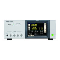
Hioki IM3533 Instruction Manual (76 pages)
LCR METER, IMPEDANCE ANALYZER
Brand:
Hioki
| Category:
Measuring Instruments
| Size: 3 MB
Table of Contents
Table of Contents
3
Introduction
5
Safety Information
5
Chapter 1 Specifications
7
RS-232C Specifications
7
GP-IB Specifications
8
USB Specifications
8
LAN Specifications
8
Chapter 2 Model IM3570/ IM3536 Connection and Setting
9
Overview of Communication
9
RS-232C Connection and Settings
12
GP-IB Connection and Settings
13
USB Settings and Connection
15
Setting USB
15
Connecting the USB Cable
16
LAN Settings and Connection
17
LAN Settings
17
LAN Settings
18
Connecting a LAN Cable
22
Remote Mode
23
Chapter 3 Model IM3523/ IM3523A Connection and Setting
25
Overview of Communication
25
USB Settings and Connection
27
Connecting the USB Cable
28
GP-IB Connection and Settings (IM3523 Only, When Connected to the Z3000)
29
Connecting the GP-IB Cable
29
RS-232C Connection and Settings (IM3523 Only, When Connected to the Z3001)
31
Connecting the RS-232C Cable
31
Setting RS-232C
32
LAN Settings and Connection (IM3523 Needs to be Connected to the Z3002)
34
LAN Settings
34
Connecting a LAN Cable
37
Remote Mode
38
Chapter 4 Model IM3533/ IM3533-01/ IM3590 Connection and Setting
39
Overview of Communication
39
USB Settings and Connection
41
USB Settings and Connection
42
GP-IB Connection and Settings (When Connected to the Z3000)
43
Connecting the GP-IB Cable
43
Setting GP-IB
43
RS-232C Connection and Settings (When Connected to the Z3001)
45
Connecting the RS-232C Cable
45
Setting RS-232C
46
LAN Settings and Connection (When Connected to the Z3002)
47
LAN Settings
47
Connecting a LAN Cable
52
Remote Mode
53
Appendix
71
Appendix 1 Checking the USB Virtual COM Port
71
Advertisement
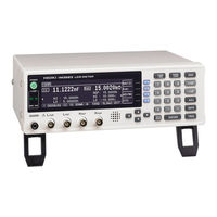
Hioki IM3533 Communication Instruction Manual (66 pages)
LCR METER IMPEDANCE ANALYZER
Brand:
Hioki
| Category:
Measuring Instruments
| Size: 1 MB
Table of Contents
Table of Contents
2
Introduction
4
Safety Information
4
Chapter 1 Specifications
5
RS-232C Specifications
5
GP-IB Specifications
6
USB Specifications
6
LAN Specifications
6
Chapter 2 Model IM3570/ IM3536 Connection and Setting
7
Overview of Communication
7
RS-232C Connection and Settings
9
GP-IB Connection and Settings
11
USB Settings and Connection
13
LAN Settings and Connection
15
Remote Mode
21
Chapter 3 Model IM3523 Connection and Setting
22
Overview of Communication
22
USB Settings and Connection
23
GP-IB Connection and Settings (When Connected to the Z3000)
25
Connecting the GP-IB Cable
25
Setting GP-IB
25
RS-232C Connection and Settings (When Connected to the Z3001)
27
Connecting the RS-232C Cable
27
Setting RS-232C
28
LAN Settings and Connection (When Connected to the Z3002)
30
LAN Settings
30
Connecting a LAN Cable
34
Remote Mode
35
Chapter 4 Model IM3533/ IM3533-01/ IM3590 Connection and Setting
36
Overview of Communication
36
USB Settings and Connection
38
GP-IB Connection and Settings (When Connected to the Z3000)
40
RS-232C Connection and Settings (When Connected to the Z3001)
42
Connecting the RS-232C Cable
42
Setting RS-232C
43
LAN Settings and Connection (When Connected to the Z3002)
44
LAN Settings
44
LAN Settings
45
Connecting a LAN Cable
49
Remote Mode
50
Chapter 5 Model IM7580 Connection and Setting
51
Overview of Communication
51
USB Settings and Connection
53
LAN Settings and Connection
55
GP-IB Connection and Settings (When Connected to the Z3000)
61
Connecting the GP-IB Cable
61
Setting GP-IB
61
RS-232C Connection and Settings (When Connected to the Z3001)
63
Connecting the RS-232C Cable
63
Setting RS-232C
64
Remote Mode
65
Appendix
66
Appendix 1 Checking the USB Virtual COM Port
66
Hioki IM3533 Instruction Manual (66 pages)
Brand:
Hioki
| Category:
Measuring Instruments
| Size: 1 MB
Table of Contents
Table of Contents
3
Introduction
5
Safety Information
5
Chapter 1 Specifications
7
RS-232C Specifications
7
GP-IB Specifications
8
USB Specifications
8
LAN Specifications
8
Chapter 2 Model IM3570 Connection and Setting
9
Overview of Communication
9
RS-232C Connection and Settings
12
Setting RS-232C
12
GP-IB Connection and Settings
13
USB Settings and Connection
15
USB Settings and Connection
16
LAN Settings and Connection
17
LAN Settings and Connection
22
Remote Mode
23
Chapter 3 Model IM3523 Connection and Setting
25
Overview of Communication
25
USB Settings and Connection
26
USB Settings and Connection
27
GP-IB Connection and Settings (When Connected to the Z3000)
28
Connecting the GP-IB Cable
28
Setting GP-IB
28
RS-232C Connection and Settings (When Connected to the Z3001)
30
Connecting the RS-232C Cable
30
Setting RS-232C
31
LAN Settings and Connection (When Connected to the Z3002)
33
Connecting a LAN Cable
37
Remote Mode
38
Chapter 4 Model IM3533/ IM3533-01/ IM3590 Connection and Setting
39
Overview of Communication
39
USB Settings and Connection
41
USB Settings and Connection
42
GP-IB Connection and Settings (When Connected to the Z3000)
43
RS-232C Connection and Settings (When Connected to the Z3001)
45
Connecting the RS-232C Cable
45
Setting RS-232C
46
LAN Settings and Connection (When Connected to the Z3002)
47
LAN Settings
47
Connecting a LAN Cable
52
Remote Mode
53
Appendix 1 Checking the USB Virtual COM Port
55
Appendix
55
Appendix 2 Checking RS-232C and USB Communication in Windows
56
Appendix 3 Checking LAN Communication in Windows
62
Advertisement
Related Products
Hioki IM3523
Hioki IM3533-01
Hioki IM3570
Hioki IM3590
Hioki IM3536
Hioki IM3536-01
Hioki IM3523A
Hioki IM7585-2
Hioki IM7581-1
Hioki IM7583 Series
Hioki Categories
Measuring Instruments
Test Equipment
Data Loggers
Multimeter
Accessories
More Hioki Manuals
Login
Sign In
OR
Sign in with Facebook
Sign in with Google
Upload manual
Upload from disk
Upload from URL