Sign In
Upload
Manuals
Brands
Gree Manuals
Air Conditioner
SUPER FREE MATCH Series
Gree SUPER FREE MATCH Series Manuals
Manuals and User Guides for Gree SUPER FREE MATCH Series. We have
4
Gree SUPER FREE MATCH Series manuals available for free PDF download: Service Manual, Owner's Manual
Gree SUPER FREE MATCH Series Service Manual (196 pages)
Brand:
Gree
| Category:
Air Conditioner
| Size: 13 MB
Table of Contents
Table of Contents
3
Product
8
Models List
8
Outdoor Unit
8
BU Module
8
Indoor Unit
9
Nomenclature
11
Nomenclature of Outdoor Unit
11
Nomenclature of BU Module
11
Nomenclature of Indoor Unit
11
Function
12
Product Data
13
Product Data of Outdoor Unit
13
Product Data of Indoor Unit
14
Product Data of BU Module
22
Working Temperature Range
22
Piping Diagram
23
Control
25
Operation Flowchart
25
Cooling/Dry Operation
26
Heating Operation
27
Main Logic
28
Control Function of Outdoor Unit
28
Protection Function
29
Other Function
30
Control Function of Indoor Unit
31
Remote Controller
34
Wired Remote Controller
34
Wireless Remote Controller YT1F (MOTO)
39
Wireless Remote Controller YAA1FB1F
42
Wireless Remote Controller YAG1FBF
46
Wireless Remote Controller YB1FAF (XFAN)
52
Smart Zone Controller (CE50-24/E)
55
General Introduction
55
Communication Network
56
Lcd
56
Buttons
57
Installation
60
Precautions for Installation
60
Key Points of Installation
62
Flow Chart of Installation
64
Outdoor Unit Installation
65
Precautions for R410A
65
Precaution for Installation
65
Precaution for Operation Test
65
Names of Main Parts
65
Parts and Components of Unit
66
Selection of Installation Location
66
Outline Dimension of the Outdoor Unit
67
Installation and Servicing Space
67
Installation of the Outdoor Unit
68
Indoor Unit Installation
69
Installation of Wall Mounted Type
69
Installation of Duct Type
71
Installation of Cassette Type
79
Installation of Floor Ceiling Type
84
Installation of Console Type
87
Bu Module Installation
92
Precaution for Installation
92
Names of Main Parts
92
Selection of Installation Location
93
Outline Dimension and Servicing Space of FXA2A-D
94
Outline Dimension and Servicing Space of FXA2B-D
95
Outline Dimension and Servicing Space of FXA3A-D
96
Outline Dimension and Servicing Space of FXA3B-D
97
Outline Dimension and Servicing Space of FXB5A-D
98
Installation Instruction
99
Refrigeration Piping Work
100
Allowable Length and Drop Height of Connecting Pipe
100
Dimension of Connecting Pipe
100
Connection of Branch Pipe
101
Design Requirements for Oil Trap
101
Connection of Outdoor Unit Refrigerant Pipe
103
Installation of Piping Adapter
103
Precaution for Connection
105
Leak Test
107
Vacuum Operation
107
Refrigerant Charging
108
Electrical Wiring Work
111
Wiring Connection
111
Requirements of Power Circuit and Cable
111
Ground Requirements
112
Precautions of Electrical Wiring Work
112
Precaution of Laying Wires
112
Electrical Wiring Work for Outdoor Unit
113
Electrical Wiring Work for BU Module
113
Instructions for DIP Switch
115
Electrical Wiring Work for Indoor Unit
115
Installation of Drainage Pipeline
116
Material Quality Requirements for Condensate Pipe
116
Key Points for Condensate Pipe Installation
116
Installation of Protective Layer on Connection Pipe
120
Maintenance
122
Testing Board Introduction
122
Compose of Testing Board
122
Instruction of Function and Data Section
122
Process Control Setting
123
Troubleshooting
125
Check before Contacting Maintenance Serviceman
125
Problem Handling
126
Error Description
126
Flow Chart of Troubleshooting
129
Malfunction Display: Current Protection
129
Malfunction Display: High Pressure Protection
130
Malfunction Display: Low Pressure Protection
131
Malfunction Display: Discharge Temperature Protection
132
Malfunction Display: High/Low Pressure Sensor Error
132
Malfunction Display: Communication Error
133
Malfunction Display: Indoor Unit Water Full Protection
134
Malfunction Display: Temperature Sensor Error
134
Power Distribution
135
Diagram of Power Distribution
135
Wiring Diagram
136
The Resistances of Common Temperature Sensors
143
15 Kω
143
20 Kω
144
50 Kω
145
Disassembly and Assembly Procedure of Main Parts
148
Outdoor Unit
148
Indoor Unit
153
Exploded Views and Part List
163
Outdoor Unit
163
Indoor Unit
165
BU Module
191
Advertisement
Gree SUPER FREE MATCH Series Service Manual (183 pages)
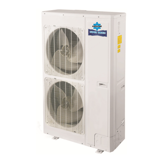
CENTRAL AIR CONDITIONERS R410A T1/R410A/60Hz
Brand:
Gree
| Category:
Air Conditioner
| Size: 35 MB
Table of Contents
Table of Contents
3
Product
8
Models List
8
Outdoor Unit
8
BU Module
8
Indoor Unit
9
Nomenclature
11
Nomenclature of Outdoor Unit
11
Nomenclature of BU Module
11
Nomenclature of Indoor Unit
11
Function
12
Product Data
13
Product Data of Outdoor Unit
13
Product Data of Indoor Unit
14
Product Data of BU Module
20
Working Temperature Range
20
Piping Diagram
21
Control
22
Operation Flowchart
23
Cooling/Dry Operation
24
Heating Operation
25
Main Logic
26
Control Function of Outdoor Unit
26
Protection Function
27
Other Function
28
Control Function of Indoor Unit
29
Wired Remote Controller
30
Remote Controller
32
Wireless Remote Controller YT1F (MOTO)
37
Wireless Remote Controller YAA1FB1F
40
Wireless Remote Controller YAG1FBF
44
Wireless Remote Controller YB1FAF (XFAN)
50
Smart Zone Controller (CE50-24/E)
53
General Introduction
53
Communication Network
54
Lcd
54
Buttons
55
Installation
57
Precautions for Installation
58
Precautions for Installation
60
Key Points of Installation
60
Flow Chart of Installation
62
Outdoor Unit Installation
63
Precautions for R410A
63
Precaution for Installation
63
Precaution for Operation Test
63
Names of Main Parts
63
Parts and Components of Unit
64
Selection of Installation Location
64
Outline Dimension of the Outdoor Unit
65
Installation and Servicing Space
65
Installation of the Outdoor Unit
66
Indoor Unit Installation
67
Installation of Wall Mounted Type
67
Installation of Duct Type
69
Installation of Cassette Type
77
Installation of Floor Ceiling Type
82
Installation of Console Type
85
Bu Module Installation
90
Precaution for Installation
90
Names of Main Parts
90
Selection of Installation Location
91
Outline Dimension and Servicing Space of FXA2A-D
92
Outline Dimension and Servicing Space of KM21-BBU12-3
93
Outline Dimension and Servicing Space of KM21-BBU13-3
93
Outline Dimension and Servicing Space of FXA3A-D
94
Refrigeration Piping Work
96
Allowable Length and Drop Height of Connecting Pipe
96
Dimension of Connecting Pipe
96
Connection of Branch Pipe
97
Design Requirements for Oil Trap
97
Connection of Outdoor Unit Refrigerant Pipe
99
Installation of Piping Adapter
99
Precaution for Connection
101
Leak Test
103
Vacuum Operation
103
Refrigerant Charging
104
Electrical Wiring Work
107
Wiring Connection
107
Requirements of Power Circuit and Cable
107
Ground Requirements
108
Precautions of Electrical Wiring Work
108
Precaution of Laying Wires
108
Electrical Wiring Work for Outdoor Unit
109
Electrical Wiring Work for BU Module
109
Instructions for DIP Switch
111
Electrical Wiring Work for Indoor Unit
111
Installation of Drainage Pipeline
112
Material Quality Requirements for Condensate Pipe
112
Key Points for Condensate Pipe Installation
112
Installation of Protective Layer on Connection Pipe
116
Maintenance
117
Testing Board Introduction
118
Compose of Testing Board
118
Instruction of Function and Data Section
118
Process Control Setting
119
Troubleshooting
121
Check before Contacting Maintenance Serviceman
121
Problem Handling
122
Error Description
122
Flow Chart of Troubleshooting
125
Malfunction Display: Current Protection
125
Malfunction Display: High Pressure Protection
126
Malfunction Display: Low Pressure Protection
127
Malfunction Display: Discharge Temperature Protection
128
Malfunction Display: High/Low Pressure Sensor Error
128
Malfunction Display: Communication Error
129
Malfunction Display: Indoor Unit Water Full Protection
130
Malfunction Display: Temperature Sensor Error
130
Power Distribution
131
Diagram of Power Distribution
131
Wiring Diagram
132
The Resistances of Common Temperature Sensors
138
15 Kω
138
20 Kω
139
50 Kω
140
Disassembly and Assembly Procedure of Main Parts
143
Outdoor Unit
143
Indoor Unit
148
Exploded Views and Part List
158
Outdoor Unit
158
Indoor Unit
160
BU Module
178
Gree SUPER FREE MATCH Series Service Manual (183 pages)
Central Air Conditioners R410A T1/R410A/60Hz
Brand:
Gree
| Category:
Air Conditioner
| Size: 20 MB
Table of Contents
Table of Contents
3
Product
8
Models List
8
Outdoor Unit
8
BU Module
8
Indoor Unit
9
Nomenclature
11
Nomenclature of Outdoor Unit
11
Nomenclature of BU Module
11
Nomenclature of Indoor Unit
11
Function
12
Product Data
13
Product Data of Outdoor Unit
13
Product Data of Indoor Unit
14
Product Data of BU Module
20
Working Temperature Range
20
Piping Diagram
21
Control
22
Operation Flowchart
23
Cooling/Dry Operation
24
Heating Operation
25
Main Logic
26
Control Function of Outdoor Unit
26
Protection Function
27
Other Function
28
Control Function of Indoor Unit
29
Wired Remote Controller
30
Remote Controller
32
Wireless Remote Controller YT1F (MOTO)
37
Wireless Remote Controller YAA1FB1F
40
Wireless Remote Controller YAG1FBF
44
Wireless Remote Controller YB1FAF (XFAN)
50
Smart Zone Controller (CE50-24/E)
53
General Introduction
53
Communication Network
54
Lcd
54
Buttons
55
Installation
57
Precautions for Installation
58
Precautions for Installation
60
Key Points of Installation
60
Flow Chart of Installation
62
Outdoor Unit Installation
63
Precautions for R410A
63
Precaution for Installation
63
Precaution for Operation Test
63
Names of Main Parts
63
Parts and Components of Unit
64
Selection of Installation Location
64
Outline Dimension of the Outdoor Unit
65
Installation and Servicing Space
65
Installation of the Outdoor Unit
66
Indoor Unit Installation
67
Installation of Wall Mounted Type
67
Installation of Duct Type
69
Installation of Cassette Type
77
Installation of Floor Ceiling Type
82
Installation of Console Type
85
Bu Module Installation
90
Precaution for Installation
90
Names of Main Parts
90
Selection of Installation Location
91
Outline Dimension and Servicing Space of FXA2A-D
92
Outline Dimension and Servicing Space of KM21-BBU12-3
93
Outline Dimension and Servicing Space of KM21-BBU13-3
93
Outline Dimension and Servicing Space of FXA3A-D
94
Refrigeration Piping Work
96
Allowable Length and Drop Height of Connecting Pipe
96
Dimension of Connecting Pipe
96
Connection of Branch Pipe
97
Design Requirements for Oil Trap
97
Connection of Outdoor Unit Refrigerant Pipe
99
Installation of Piping Adapter
99
Precaution for Connection
101
Leak Test
103
Vacuum Operation
103
Refrigerant Charging
104
Electrical Wiring Work
107
Wiring Connection
107
Requirements of Power Circuit and Cable
107
Ground Requirements
108
Precautions of Electrical Wiring Work
108
Precaution of Laying Wires
108
Electrical Wiring Work for Outdoor Unit
109
Electrical Wiring Work for BU Module
109
Instructions for DIP Switch
111
Electrical Wiring Work for Indoor Unit
111
Installation of Drainage Pipeline
112
Material Quality Requirements for Condensate Pipe
112
Key Points for Condensate Pipe Installation
112
Installation of Protective Layer on Connection Pipe
116
Maintenance
117
Testing Board Introduction
118
Compose of Testing Board
118
Instruction of Function and Data Section
118
Process Control Setting
119
Troubleshooting
121
Check before Contacting Maintenance Serviceman
121
Problem Handling
122
Error Description
122
Flow Chart of Troubleshooting
125
Malfunction Display: Current Protection
125
Malfunction Display: High Pressure Protection
126
Malfunction Display: Low Pressure Protection
127
Malfunction Display: Discharge Temperature Protection
128
Malfunction Display: High/Low Pressure Sensor Error
128
Malfunction Display: Communication Error
129
Malfunction Display: Indoor Unit Water Full Protection
130
Malfunction Display: Temperature Sensor Error
130
Power Distribution
131
Diagram of Power Distribution
131
Wiring Diagram
132
The Resistances of Common Temperature Sensors
138
15 Kω
138
20 Kω
139
50 Kω
140
Disassembly and Assembly Procedure of Main Parts
143
Outdoor Unit
143
Indoor Unit
148
Exploded Views and Part List
158
Outdoor Unit
158
Indoor Unit
160
BU Module
178
Advertisement
Gree SUPER FREE MATCH Series Owner's Manual (98 pages)
Brand:
Gree
| Category:
Air Conditioner
| Size: 7 MB
Table of Contents
English
5
Table of Contents
5
Safety Precautions
7
Attention for Installation
9
Precautions for R410A
9
Precaution for Installation
9
Precaution for Operation Test
9
Accessories
9
Product Introduction
10
Names of Main Parts
10
Combinations for Outdoor and Indoor Units
10
Parts and Components of Unit
11
Working Temperature Range
11
Selection of Installation Location and Precautions
12
Selection of Installation Location
12
Outline Dimension of Outdoor Unit
13
Installation and Servicing Space
13
Installation Instruction
14
Installation of Refrigerant Pipes
15
Allowable Length and Drop Height of Connecting Pipe
15
Connection of Branch Pipe
16
Connection of Refrigerant Pipes
17
Connection of Refrigerant Pipe
18
Leak Test
19
Vacuum Operation
19
Refrigerant Charging
20
Wiring Connection
23
Electrical Wiring Work
23
Requirements of Power Circuit and Cable
24
Ground Requirements
25
Precautions of Electrical Wiring Work
25
Precaution of Laying Wires
26
Procedures for Electrical Wiring Work
26
Design of Drainage Pipeline
27
Installation of Drain Hose
27
Installation of Protective Layer
28
Test Operation
29
Check after Installation
29
Troubleshooting
30
Check before Contacting Service Center
30
Problem Handling
31
Error Description
31
Maintenance
34
Outdoor Condenser
34
Drain Pipe
34
Check before the Seasonal Use
34
Maintenance after Seasonal Use
34
After-Sales Service
35
Español
38
Accesorios
42
Indicaciones para la Instalación
42
Precauciones para el R410A
42
Precauciones para la Instalación
42
Precauciones para Pruebas de Funcionamiento
42
Combinaciones de Unidades Interiores y Exteriores
43
Denominaciones de las Piezas Principales
43
Información del Producto
43
Piezas y Componentes de la Unidad
44
Rango de Temperatura de Funcionamiento
44
Dimensiones de la Unidad Interior
45
Espacio de Instalación y Mantenimiento
45
Instrucciones de Instalación
46
Instalación de Tuberías de Refrigerante
47
Longitud y Altura Permitidas de la Tubería de Conexión
47
Conexión de la Tubería de Bifurcación
48
Tamaño de las Tuberías de Conexión
48
Conexión de Tuberías de Refrigerante
49
Conexión de Tubería de Refrigerante
50
Prueba de Fugas
51
Carga de Refrigerante
52
Cableado Eléctrico
55
Conexión de Cables
55
Requisitos del Circuito Eléctrico y el Cable
56
Precauciones para el Cableado
57
Requisitos de Puesta a Tierra
57
Precauciones para el Tendido de Cables
58
Procedimientos de Cableado Eléctrico
58
Diseño de la Línea de Drenaje
59
Instalación de la Manguera de Drenaje
59
Instalación de la Capa Protectora
60
Comprobaciones tras la Instalación
61
Prueba de Funcionamiento
61
Comprobaciones Antes de Llamar al Servicio Técnico
62
Tratamiento de Problemas
63
Combinaisons D'unités Extérieures et Intérieures
73
Désignation des Pièces Principales
73
Présentation du Produit
73
Connexion du Tuyau de Réfrigérant
79
Fonctionnement à Vide
82
Test de Fuite
82
Charge de Réfrigérant
83
Connexion de Câblage
86
Travaux de Câblage Électrique
86
Exigences du Circuit et du Câble D'alimentation
87
Exigences de Mise à la Terre
88
Précautions de Câblage Électrique
88
Précautions de Pose des Câbles
89
Conception de la Tuyauterie D'évacuation
90
Pose du Tuyau D'évacuation
90
Pose de la Couche de Protection
91
Contrôle après Installation
92
Test de Fonctionnement
92
11 Dépannage
93
Inspection Préalable à une Demande D'assistance
93
Description des Erreurs
94
Entretien après Utilisation Saisonnière
97
Inspection Avant Utilisation Saisonnière
97
Maintenance
97
Tuyau D'évacuation
97
Unité Extérieure
97
Service Après-Vente
98
Advertisement
Related Products
Gree Fresh Air Series
Gree FP-18XD-E
Gree FP-85XDT/B-K
Gree FP-68BA3/B-K
Gree FP-34BA5/B-D
Gree FP-102BA5/B-D
GREE FP-102WAS/G-K
GREE FP-136WAF-R
GREE FP-136WAH/G-D
GREE FP-102WAS/G-D
Gree Categories
Air Conditioner
Heat Pump
Dehumidifier
Controller
Air Handlers
More Gree Manuals
Login
Sign In
OR
Sign in with Facebook
Sign in with Google
Upload manual
Upload from disk
Upload from URL