Sign In
Upload
Manuals
Brands
Gotting Manuals
Controller
HG G-73650ZD
Gotting HG G-73650ZD Manuals
Manuals and User Guides for Gotting HG G-73650ZD. We have
2
Gotting HG G-73650ZD manuals available for free PDF download: Basics, Setup And Software
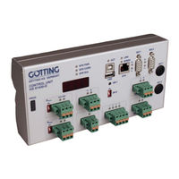
Gotting HG G-73650ZD Basics, Setup And Software (206 pages)
Navigation Controller
Brand:
Gotting
| Category:
Controller
| Size: 11 MB
Table of Contents
Overview
3
Table of Contents
3
Introduction
8
Presentation of Information
8
Warning Notices
8
Symbols
9
Table 1 Hazard Classification According to ANSI Z535.6-2006
9
Intended Use
10
Tasks of the Navigation Controller
10
Requirements / Options
11
Basic Principles of Track Guidance
12
Chapter 13 - List of Figures
12
Figure 1 Example: Suitable Vehicle Types (Selection)
12
Figure 2 Sketch: Suitable Vehicle Types
12
Suitable and Unsuitable Vehicle Types
12
Figure 3 Block Diagram System Structure
13
Position Determination with Sensor Fusion
13
System Composition
13
Freeze ONS
14
The Odometry
14
Compensation of Wheel Diameters
15
Sensors for Navigation
15
Transponder Antenna
15
Figure 4 Determination of Antenna Positions Underneath the Vehicle
16
Figure 5 Single Antenna: Placement
16
Single Antenna Evaluation - Calculation of the Position with One Antenna
16
Figure 6 Properties of a Single Antenna Set-Up
17
Double Antenna Evaluation
18
Figure 7 Properties of a Double Antenna Set-Up
18
Figure 8 Properties of a Triple Antenna Set-Up
19
Initialising the Transponder Sensor Fusion (Placing Vehicle on the Track)
19
The Triple Antenna Evaluation
19
Table 2 Definition of Transponder List
20
The GPS/GNSS System
20
The Transponder List
20
Coordinate Systems
21
Figure 10 Vehicle Coordinate System
21
Figure 9 Arrangement of the GPS Antennas
21
The Vehicle Coordinate System
21
Characteristics of the Coordinate Systems
22
Figure 11 Cylindrical Intersection of the Earth Globe for a Flat Country Coordinate System
22
The Local Coordinate System
22
Figure 12 Example: Virtual Track with Support Points
23
Reconstruction of the Route (Segments)
23
Virtual Tracks
23
Figure 13 Example of a Segment File with Support Points
24
Structure of the Segment File
24
Table 3 Structure of a Segment File with Support Points
24
The Segment File
24
Figure 14 Example for Congruent Segments
25
Figure 15 Segment FIFO Shifting Register
26
Selection of Segments
26
The Segment Search
26
Table 4 Example: Shifting of Segments in the FIFO
27
Table 5 Example: Adding New Segments to the FIFO
27
FTP Transmission of Segments
28
Transmission of Segments
28
Attributes
29
Offset Driving
29
Figure 16 Offset Segments
30
Figure 17 Example: Offset Driving
30
Figure 18 Example: Inverted Steering
31
Inverted Steering
31
Figure 19 Example: Steering Not Inverted
32
Spot Turn
32
Stop Distance
32
Creating / Editing of a Segment File
33
Figure 20 Online Track Editor by Götting
33
Track Guidance
33
Figure 21 Example Course with a Driving Job Consisting of a Combination of Segments
34
Figure 22 Speed in Segments: Linear Ramp
35
Figure 23 Speed in Segments: Speed in Relation to Time
35
Ramps in the Navigation Controller
35
Speed Calculation
35
Figure 24 Speed in Segments: Impact of the Ramps
36
Figure 25 Speed in Segments: Ramps with Reduced Acceleration
36
Speed Ramp
36
Adjustment of the Speed by the PLC
37
Automatic Adjustment of Segment Speeds
37
Figure 26 Acceleration Ramps
37
Figure 27 Speed Ramp
37
Stop Ramp
37
Figure 28 Speed Correction before Segment Change
38
Figure 29 Wrong Speed Correction
38
Figure 30 Guidance of an Omnidirectional Vehicle
38
Guidance of an Omnidirectional Vehicle
38
Steering Angle Calculation
38
Figure 31 Guiding an Omnidirectional Vehicle: Control Process
39
Figure 32 Formula: Limitation of Angles
39
Guidance of a Non-Omnidirectional Vehicle
39
Figure 33 Forward Guidance of a Non-Omnidirectional Vehicle
40
Figure 34 Backwards Guidance of a Non-Omnidirectional Vehicle
40
Reverse Driving with a Trailer
40
Figure 35 Important Values for the Reverse Driving with Trailer
41
Measuring Section
41
Automatic Mode
42
Driving Modes
42
Idle Mode
42
Parameter Test Mode
42
Remote Control Mode
42
Vector Steering Mode
43
Communication with the Vehicle Control (E.g. PLC)
44
Figure 36 Photo of the Control Unit: Basic Configuration and Version Including the Feldbus/Profinet Extension Module HG G-61432ZA and with Option GPS
45
Hardware
45
Control Elements on Front Panel
46
Figure 37 Dimensions of the Control Unit Hardware HG G-61430ZD
46
Figure 38 Leds and Connectors
46
Front Panel
46
Mounting
46
Table 6 Control Elements of the Control Unit
46
Display Elements on Front Panel
47
Table 7 Display Elements
47
Connectors
48
Eth
48
Figure 39 Sketch of Connector ETH
48
Figure 40 Sketch USB Connectors Type a and Type B
48
Figure 41 Sketch of Connector SIO 1
48
SIO 1 (GPS Receiver)
48
Table 8 Pin Assignment SIO 1
48
Usb
48
Can 1
49
Figure 42 Sketch of Connector SIO 2
49
Figure 43 Sketch of Connector CAN 1
49
Sio 2
49
Table 10 Pin Assignment SIO 2
49
Table 9 Pin Assignment SIO 2
49
Can 2
50
Figure 44 Sketch of Connector CAN 2
50
Figure 45 Sketch of Connector SIO 3
50
Figure 46 Sketch of Connector POWER
50
Power
50
Sio 3
50
Table 11 Pin Assignment SIO 2
50
Table 12 Pin Assignment SIO 3
50
Table 13 Pin Assignment SIO 2
50
Ant1 / Ant2
51
Encoder 1 / Encoder 2
51
Figure 47 Sketch of Connector IO
51
Figure 48 Sketch of Connectors ENCODER 1 / ENCODER 2
51
Figure 49 Sketch of Connector PROG
51
Prog
51
Table 14 Pin Assignment SIO 2
51
Table 15 Pin Assignment ENCODER 1 / ENCODER 2
51
Extension Module Feldbus
52
Figure 50 Dimensions Control Unit Incl. Expansion Module HG G-61432ZA
52
Configuration Via Web Sites
53
Figure 51 Screenshot: Main Menu
54
Main Menu
54
Figure 52 Screenshot: Status -> Navigation
55
Navigation Menu
55
Status
55
Status Menu
55
Deviation
56
Seg. Table
56
Segment
56
Plc
57
Antenna
58
Figure 53 Screenshot: Status -> Transponder
58
Transponder Menu
58
Odometry
59
Result
59
Figure 54 Screenshot: Status -> GPS
60
Gps
60
GPS Menu
60
Ons
60
Controller Correction
61
Controller Deviation
61
Status
61
Figure 55 Screenshot: Status -> GPS Receiver
62
GPS Receiver Menu
62
Position
62
Status
62
Utc
62
Accuracy
63
Base Vector
63
Diff. Data Age
63
Heading
63
Satellites
63
Error Menu
64
Figure 56 Screenshot: Status -> Error with Tooltip Shown for Byte 3 > Trailer
64
Configuration Menu
65
Figure 57 Screenshot: Status -> TCP
65
TCP Menu
65
Configuration -> Main
66
Figure 58 Screenshot: Configuration -> Main
66
Configuration -> Guidance
68
Figure 59 Screenshot: Configuration -> Guidance
68
Figure 60 Control Via Instantaneous Center of Rotation
69
What Type of Vehicle Is Involved
69
Wheels
69
Figure 61 Example: Non-Omnidirectional Vehicle
70
Figure 62 Example: Symmetrically Steerable Axles (Non-Omnidirectional Vehicle)
70
The Non-Omnidirectional Vehicle
70
Figure 63 Example: Omnidirectional Vehicle
71
Figure 64 Specification of the Position Data to be Determined for a Vehicle
71
How Are the Positions Specified on the Vehicle
71
The Omnidirectional Vehicle
71
Which Wheels Should be Used for the Odometry
71
Configuration -> Wheels
72
Figure 65 Screenshot: Configuration -> Wheels
72
Configuration -> Antenna
74
Figure 66 Screenshot: Configuration -> Antenna
74
Configuration -> Accuracy
75
Figure 67 Screenshot: Configuration -> Accuracy
75
Configuration -> Steer Controller
76
Figure 68 Control of an Omnidirectional Vehicle
76
Figure 69 Screenshot: Configuration -> Steer Controller
77
Figure 70 Formula: Limitation of Angles
77
Configuration -> Speed Controller
78
Figure 71 Screenshot: Configuration -> Speed Controller
78
Configuration -> Sensor Fusion Transponder
80
Figure 72 Screenshot: Configuration -> Sensor Fusion Transponder
80
Configuration -> Sensor Fusion GPS
81
Figure 73 Screenshot: Configuration -> Sensor Fusion GPS
81
Configuration -> Gyro
83
Figure 74 Screenshot: Configuration -> Gyro
83
Configuration -> Servo
84
Figure 75 Screenshot: Configuration -> Servo
84
Figure 76 Servo: Diagram Control Value and Controller Difference
86
Configuration -> Trailer
87
Figure 77 Formula: Distortion of the D Component Along Tv
87
Figure 78 Screenshot: Configuration -> Trailer
87
Figure 79 Screenshot: Network - Settings
89
Network Menu
89
Config File Menu
90
Figure 80 Screenshot: Config File - Upload/Download
90
Upload Configuration
90
Download
91
Figure 81 Screenshot: Segment File - Upload/Download
91
Segment File Menu
91
Upload Segment File
91
Download Segment File
92
Figure 82 Screenshot: Segment Table
92
Segment Table Menu
92
Figure 83 Screenshot: Transponder File - Upload/Download
93
Transponder File Menu
93
Upload Transponder File
93
Download Transponder File
94
Figure 84 Screenshot: Transponder Table
94
Transponder Table Menu
94
Figure 85 Screenshot: Parameter Test
95
Parameter Test Menu
95
Possibilities in the 'Idle' Mode
96
Requirements for Switching into the Different Modes
96
Possibilities in the 'Auto' Mode
97
Possibilities in the 'Test' Mode
97
Setting a Starting Position
97
Specification of Segments
97
Configuration Via Terminal Program
98
Connection Establishment
98
Table 16 Terminal Program: Parameter for the Connection Establishment
98
Figure 86 Terminal Program: Main Menu
99
Main Menu
99
A: Main Monitor Navigation
100
Display Output
100
Figure 87 Terminal Program: Menu Main Monitor Navigation
100
Table 17 Main Monitor Navigation: Section Vehicle
100
Table 18 Main Monitor Navigation: Section Target
100
Table 19 Main Monitor Navigation: Section Deviation
101
Table 20 Main Monitor Navigation: Section Segment
101
Input Possibilities
102
Table 21 Main Monitor Navigation: Section Error
102
Table 22 Main Monitor Navigation: Section Steering
102
B: Main Monitor Sensorfusion
103
Display Output
103
Figure 88 Terminal Program: Menu Main Monitor Sensorfusion
103
Table 23 Main Monitor Sensorfusion: Section Antenna 1 / 2 / 3
103
Input Possibilities
104
Table 24 Main Monitor Sensorfusion: Section Odometrie
104
Table 25 Main Monitor Sensorfusion: Section Transponder Position
104
D: Data Logging
105
Figure 89 Terminal Program: Menu Datalogging
105
Figure 90 Terminal Program: Capture Text (Data Logging)
105
Display Output
106
E: Parameter Test
106
Figure 91 Terminal Program: Menu Parameter Test
106
Table 26 Parameter Test: Section Position
106
Input Possibilities
107
Table 27 Parameter Test: Abschnitt Odometric System
107
Table 28 Parameter Test: Section Target and Current Steering Angle
107
Figure 92 Terminal Program: Menu Segment Directory
108
N: Show Segments
108
Table 29 Parameter Test: Input Possibilties
108
Figure 93 Terminal Program: Menu Show Transponder
109
Q: Show Transponder
109
S: Segment Sequences
109
Figure 94 Terminal Program: Segment Sequences
110
Commissioning
111
Interfaces Usually Connected
111
Test / Real Operation
111
Commissioning the Communication
112
Setting the Parameters
112
Configuration -> Main
113
Table 30 Example Commissioning Parameters in Config. Main
113
Configuration -> Guidance
114
Table 31 Example Commissioning Parameters in Config. Guidance
114
Configuration -> Wheels
115
Figure 95 Schematic Diagram of a Forklift Truck
115
Table 32 Example Commissioning Parameters in Config. Wheels: Wheel 1
115
Table 33 Example Commissioning Parameters in Config. Wheels: Wheel 2
116
Configuration -> Antenna
117
Table 34 Example Commissioning Parameters in Config. Wheels: CAN Interface
117
Table 35 Example Commissioning Parameters in Config. Wheels: Wheel 3
117
Table 36 Example Commissioning Parameters in Config. Wheels: Wheel 4
117
Table 37 Example Commissioning Parameters in Config. Antenna
117
Configuration -> Accuracy
118
Configuration -> Steer Controller
118
Table 38 Example Commissioning Parameters in Config. Accuracy
118
Table 39 Example Commissioning Parameters in Config. Steer Controller
118
Configuration -> Sensorfusion GPS
119
Configuration -> Sensorfusion Transponder
119
Configuration -> Speed Controller
119
Table 40 Example Commissioning Parameters in Config. Speed Controller
119
Chapter 14 - List of Tables
119
Table 41 Example Commissioning Parameters in Config. Sensor Fusion
119
Configuration -> Gyro
120
Configuration -> Servo
120
Configuration -> Trailer
120
Creating the Segments
120
Table 42 Example Commissioning Parameters in Config. Gyro
120
Simulation Without Vehicle and Vehicle Controller
121
Commissioning a Vehicle
122
Simulation Without Vehicle and with Vehicle Controller
122
Testing and Optimizing the Parameters
123
Figure 96 Formula: Correction of 'Increment / Meters
124
Figure 97 Test Run 1 at Two Transponders
125
Figure 98 Test Run 2 at Two Transponders
125
Figure 99 the Actual and Target Steering Angle over Time Are Shown in 10 Ms Steps
126
Other Optimisations
126
Figure 100 Characteristics of Differently Adj. Steering Controllers over Time
127
Optimizing the Steering Controller
127
Optimizing the Speed Ramps
128
CAN Bus Protocol
130
Figure 101 CAN Synchronization Via Counters
130
How to Send Segments to the Control Unit Via the CAN Bus
130
Figure 102 State Machine Segment Transmission Via CAN Buffers
131
Path Data Box
132
Status Box
132
Table 43 CAN Rx Telegram: Status Box
132
Table 44 CAN Tx Telegram: Path Data (Actual)
132
Transmission Telegrams from Control Unit to PLC, the Wheels and the Gyro
132
Segment Search Box
134
Table 45 CAN Tx Telegram: Segment Search
134
Error Box
135
Figure 103 CAN Error Telegram Transmission/Synchronization Sequence
136
Table 46 CAN Telegram: Error
137
Table 47 CAN Error Codes
138
Sensorfusion Boxes
140
Table 48 CAN Tx Telegram: Wheel Tx
141
Table 49 Wheel Tx Command Bits
141
Wheel Boxes
141
CAN Open Start / Stop Box
142
Table 50 CAN Tx Telegram: Wheel Tx Virtual
142
Table 51 Wheel Tx Virtual Command Bits
142
Table 52 CAN Tx Telegram: CAN Open Start / Stop
142
Gyro Box
143
Servo Box
143
Table 53 CAN Tx Telegram: Servo
143
Table 54 CAN Tx Telegram: Gyro
143
Angle and Speed Box
144
ME1 Box
144
Table 55 CAN Tx Telegram: Angle and Speed
144
Table 56 CAN Tx Telegram: ME1
144
ME2 Box
145
Pol X/Y CAN2 Box
145
Table 57 CAN Tx Telegram: ME2
145
Table 58 CAN Tx Telegram: Pol X/Y CAN2
145
PLC Control Box
146
Polar CAN 1 / CAN 2 / CAN 1+2 Box
146
Reception Telegrams from PLC, Wheels, Antennas, Gyro and Sensor Fusion to the Control Unit
146
Table 59 CAN Tx Telegram: Polar CAN 1 / CAN 2 / CAN 1+2
146
Table 60 CAN Rx Telegram: Control Box
146
Path Data (Target) Box
148
Table 61 CAN Rx Telegram: Path Data (Target)
148
Remote Control Box
149
Table 62 CAN Rx Telegram: Remote Control
149
Table 63 CAN Rx Telegram: Wheel Rx
150
Table 64 Wheel Rx Status Bits
150
Wheel Box
150
Antenna Boxes
151
Servo Box
151
Table 65 CAN Rx Telegram: Servo
151
Table 66 CAN Rx Telegram: Antenna Status, Code and Deviation
151
Table 67 CAN Rx Telegram: Antenna Info
151
Gyro Box
152
Table 68 CAN Rx Telegram: Gyro
152
Sensor Fusion Boxes
153
Table 69 CAN Rx Telegram: Sensorfusion Position X, Heading, Aerea Nr
153
Table 70 CAN Rx Telegram: Sensorfusion Position Y, Heading, Status of Navigation
154
Table 71 CAN Sensorfusion Status Byte
154
Table 72 CAN Sensorfusion Boxes Coding of the Accuracy
155
Table 73 CAN Rx Telegram: Vector
155
Vector Box
155
Contelec Steering Encoder Box
156
ME PDO 1 Box
156
Steering Encoder Box
156
Table 74 CAN Rx Telegram: Steering Encoder
156
Table 75 CAN Rx Telegram: Contelec Steering Encoder
156
Table 76 CAN Rx Telegram: ME PDO 1
156
ME PDO 2 Box
157
ME PDO 3 Box
157
Table 77 CAN Rx Telegramm: ME PDO 2
157
Table 78 CAN Rx Telegramm: ME PDO 3
157
Table 79 CAN Rx Telegram: Wheel Reduction
157
Wheel Reduction Box
157
Segment Sequence Box
158
Table 80 CAN Rx Telegram: Trailer
158
Trailer Box
158
Table 81 CAN Rx Telegram: Segment Sequences
159
Feldbus/Ethernet (UDP) Output
160
Table 82 Feldbus Protocol Tx Telegram Control Unit -> PLC
160
Tx Transmission Telegram Control Unit -> PLC
160
Rx Reception Telegram PLC -> Control Unit
166
Table 83 Feldbus Protocol Rx Telegram PLC -> Control Unit
167
Opening Logged Data in Excel
171
USB Data Logging: Scope of the Data
171
List of Logged Parameters
172
Table 84 List of the Parameters Logged on a USB Memory Stick
172
Table 85 Trouble Shooting
185
Trouble Shooting
185
Technical Data
187
Appendix
188
Attributes
188
Definition of Segment Sequences
189
Steering Via Segment Sequences
189
Figure 104 Formula: Equation for the Calculation of 16 Bit Radii
190
Radius Calculation with 16 Bit Resolution
190
Starting Segment Sequences
190
Configuration of the Ethernet Interface Parameters Via SIO 2
191
Figure 105 Increased Radius Range through Transformation
191
Figure 106 Resolution of the Radius after Transformation
191
Figure 107 Screenshot: Software for Setting T. Parameters of T. Ethernet Interface Via
192
Firmware-Update Via the USB Interface
192
Figure 108 Firmware Update Software: Start Screen
193
Figure 109 Firmware Update Software: Adjust Options
193
Figure 110 Firmware Update Software: Choose Firmware File
194
Figure 111 Firmware Update Software: Start the Update
194
Figure 112 Firmware Update Software: Confirmation Dialog
194
Figure 113 Firmware Update Software: Update in Progress
195
196 List of Figures
196
List of Tables
199
Index
202
Copyright
205
Copyright and Terms of Liability
205
Exclusion of Liability
205
Trade Marks and Company Names
205
Advertisement
Gotting HG G-73650ZD Basics, Setup And Software (158 pages)
Navigation Controller
Brand:
Gotting
| Category:
Controller
| Size: 6 MB
Table of Contents
Table of Contents
3
Introduction
8
Symbols
8
Tasks of the Navigation Controller
9
Intended Use
9
Requirements / Options
10
Basic Principles of Track Guidance
11
Suitable and Unsuitable Vehicle Types
11
Figure 1 Example: Suitable Vehicle Types (Selection)
11
Figure 2 Sketch: Suitable Vehicle Types
11
System Composition
12
Position Determination with Sensor Fusion
12
Figure 3 Block Diagram System Structure
12
The Odometry
13
Sensors for Navigation
13
Transponder Antenna
13
Single Antenna Evaluation - Calculation of the Position with One Antenna
14
Figure 4 Determination of Antenna Positions Underneath the Vehicle
14
Figure 5 Single Antenna: Placement
14
Figure 6 Properties of a Single Antenna Set-Up
15
Double Antenna Evaluation
16
Figure 7 Properties of a Double Antenna Set-Up
16
The Triple Antenna Evaluation
17
Initialising the Transponder Sensor Fusion (Placing Vehicle on the Track)
17
Figure 8 Properties of a Triple Antenna Set-Up
17
The Transponder List
18
Gps
18
Table 1 Definition of Transponder List
18
Coordinate Systems
19
The Vehicle Coordinate System
19
The Local Coordinate System
19
Figure 9 Vehicle Coordinate System
19
Characteristics of the Coordinate Systems
20
Figure 10 Cylindrical Intersection of the Earth Globe for a Flat Country Coordinate System
20
Reconstruction of the Route (Segments)
21
Virtual Tracks
21
Figure 11 Example: Virtual Track with Support Points
21
The Segment File
22
Structure of the Segment File
22
Figure 12 Example of a Segment File with Support Points
22
Table 2 Structure of a Segment File with Support Points
22
The Segment Search
23
Figure 13 Example for Congruent Segments
23
Selection of Segments
24
Figure 14 Segment FIFO Shifting Register
24
Transmission of Segmente
25
Table 3 Example: Shifting of Segments in the FIFO
25
Table 4 Example: Adding New Segments to the FIFO
25
Attributes
26
Offset Driving
26
Figure 15 Offset Segments
26
Inverted Steering
27
Figure 16 Example: Offset Driving
27
Figure 17 Example: Inverted Steering
27
Stop Distance
28
Figure 18 Example: Steering Not Inverted
28
Spot Turn
29
Creating / Editing of a Segment File
29
Figure 19 Online Track Editor by Götting
30
Track Guidance
31
Figure 20 Example Course with a Driving Job Consisting of a Combination of Segments
31
Speed Calculation
32
Steering Angle Calculation
32
Guidance of an Omnidirectional Vehicle
32
Figure 21 Guidance of an Omnidirectional Vehicle
32
Figure 22 Guiding an Omnidirectional Vehicle: Control Process
33
Figure 23 Formula: Limitation of Angles
33
Guidance of a Non-Omnidirectional Vehicle
34
Driving Modes
34
Figure 24 Forward Guidance of a Non-Omnidirectional Vehicle
34
Figure 25 Backwards Guidance of a Non-Omnidirectional Vehicle
34
Idle Mode
35
Parameter Test Mode
35
Automatic Mode
35
Remote Control Mode
35
Vector Steering Mode
36
Communication with the Vehicle Control (E.g. PLC)
36
Hardware
38
Figure 26 Photo of the Control Unit: Basic Configuration and Version Including the Feldbus/Profinet Extension Module and with Option GPS
38
Mounting
39
Front Panel
39
Control Elements on Front Panel
39
Figure 27 Dimensions of the Control Unit Hardware HG G-61430ZD
39
Figure 28 Led's and Connectors
39
Table 5 Control Elements of the Control Unit
39
Display Elements on Front Panel
40
Connectors
40
Eth
40
Figure 29 Sketch of Connector ETH
40
Table 6 Display Elements
40
Usb
41
SIO 1 (GPS Receiver)
41
Sio 2
41
Figure 30 Sketch USB Connectors Type a and Type B
41
Figure 31 Sketch of Connector SIO 1
41
Figure 32 Sketch of Connector SIO 2
41
Table 7 Pin Assignment SIO 1
41
Table 8 Pin Assignment SIO 2
41
Can 1
42
Can 2
42
Sio 3
42
Figure 33 Sketch of Connector CAN 1
42
Figure 34 Sketch of Connector CAN 2
42
Figure 35 Sketch of Connector SIO 3
42
Table 9 Pin Assignment SIO 2
42
Table 10 Pin Assignment SIO 2
42
Table 11 Pin Assignment SIO 2
42
Power
43
Encoder 1 / Encoder 2
43
Figure 36 Sketch of Connector POWER
43
Figure 37 Sketch of Connector IO
43
Figure 38 Sketch of Connectors ENCODER 1 / ENCODER 2
43
Table 12 Pin Assignment SIO 2
43
Table 13 Pin Assignment SIO 2
43
Table 14 Pin Assignment ENCODER 1 / ENCODER 2
43
Prog
44
Ant1 / Ant2
44
Extension Module Feldbus
44
Figure 39 Sketch of Connector PROG
44
Figure 40 Dimensions Control Unit Incl. Expansion Module
44
Software
45
Main Menu
46
Figure 41 Screenshot: Main Menu
46
Status Menu
47
Navigation Menu
47
Status
47
Figure 42 Screenshot: Status -> Navigation
47
Deviation
48
Seg. Table
48
Segment
48
Plc
49
Transponder Menu
50
Antenna
50
Figure 43 Screenshot: Status -> Transponder
50
Result
51
Odometry
51
Gps
52
Figure 44 Screenshot: Status -> GPS
52
Ons
53
Controller Deviation
53
Controller Correction
53
Status
54
GPS Receiver
55
Utc
55
Status
55
Position
55
Diff. Data Age
55
Satellites
55
Accuracy
55
Figure 45 Screenshot: Status -> GPS Receiver
55
Base Vector
56
Heading
56
Error
57
Figure 46 Screenshot: Status -> Error
57
Tcp
58
Configuration Menu
58
Figure 47 Screenshot: Status -> TCP
58
Configuration -> Main
59
Figure 48 Screenshot: Configuration -> Main
59
Configuration -> Guidance
61
Wheels
61
Figure 49 Screenshot: Configuration -> Guidance
61
What Type of Vehicle Is Involved
62
The Non-Omnidirectional Vehicle
62
Figure 50 Example: Non-Omnidirectional Vehicle
62
Figure 51 Example: Symmetrically Steerable Axles (Non-Omnidirectional Vehicle)
62
The Omnidirectional Vehicle
63
Which Wheels Should be Used for the Odometry
63
How Are the Positions Specified on the Vehicle
63
Figure 52 Example: Omnidirectional Vehicle
63
Figure 53 Specification of the Position Data to be Determined for a Vehicle
63
Configuration -> Wheels
64
Figure 54 Screenshot: Configuration -> Wheels
64
Configuration -> Antennas
66
Figure 55 Screenshot: Configuration -> Antenna
66
Configuration -> Accuracy
67
Figure 56 Screenshot: Configuration -> Accuracy
67
Configuration -> Steer Controller
68
Figure 57 Control of an Omnidirectional Vehicle
68
Figure 58 Screenshot: Configuration -> Steer Controller
69
Figure 59 Formula: Limitation of Angles
69
Configuration -> Speed Controller
70
Figure 60 Screenshot: Configuration -> Speed Controller
70
Configuration -> Sensor Fusion Transponder
71
Figure 61 Screenshot: Configuration -> Sensor Fusion Transponder
71
Configuration -> Sensor Fusion GPS
72
Figure 62 Screenshot: Configuration -> Sensor Fusion GPS
73
Configuration -> Gyro
75
Figure 63 Screenshot: Configuration -> Gyro
75
Configuration -> Servo
76
Figure 64 Screenshot: Configuration -> Servo
76
Figure 65 Formula: Actuating Variable Calculation with Controller Boost
77
Network Menu
78
Figure 66 Screenshot: Network - Settings
78
Config File Menu
79
Upload Configuration -> Load Parameters from a File on the PC into the Navigation Controller
79
Figure 67 Screenshot: Config File - Upload/Download
79
Download -> Transfer Parameters from Navigation Controller into a File on the PC
80
Segment File Menu
80
Upload Segment File -> Transfer a Segment File from the PC into the Navigation Con- Troller
80
Figure 68 Screenshot: Segment File - Upload/Download
80
Download Segment File -> Transfer Segment File from the Navigation Controller into a File on the PC
81
Segment Table Menu
82
Figure 69 Screenshot: Segment Table
82
Transponder File Menu
83
Upload Transponder File -> Transfer a Transponder File from the PC into the Navigation Controller
83
Figure 70 Screenshot: Transponder File - Upload/Download
83
Download Segment File -> Transfer Transponder File from the Navigation Controller into a File on the PC
84
Transponder Table Menu
84
Figure 71 Screenshot: Transponder Table
84
Parameter Test' Menu
85
Requirements for Switching into the Different Modes
85
Figure 72 Screenshot: Parameter Test
85
Possibilities in the 'Idle' Mode
86
Possibilities in the 'Test' Mode
86
Possibilities in the 'Auto' Mode
86
Specification of Segments
86
Setting a Starting Position
87
Commissioning
88
Interfaces Usually Connected
88
Test / Real Operation
88
Commissioning the Communication
89
Setting the Parameters
89
Configuration -> Main
90
Table 15 Example Commissioning Parameters in Config. Main
90
Configuration -> Guidance
91
Configuration -> Wheels
91
Figure 73 Schematic Diagram of a Forklift Truck
91
Table 16 Example Commissioning Parameters in Config. Guidance
91
Table 17 Example Commissioning Parameters in Config. Wheels: Wheel 1
92
Table 18 Example Commissioning Parameters in Config. Wheels: Wheel 2
92
Configuration -> Antenna
93
Table 19 Example Commissioning Parameters in Config. Wheels: CAN Interface
93
Table 20 Example Commissioning Parameters in Config. Antenna
93
Configuration -> Accuracy
94
Configuration -> Steer Controller
94
Configuration -> Speed Controller
94
Table 21 Example Commissioning Parameters in Config. Accuracy
94
Table 22 Example Commissioning Parameters in Config. Steer Controller
94
Table 23 Example Commissioning Parameters in Config. Speed Controller
94
Configuration -> Sensor Fusion
95
Configuration -> Gyro
95
Table 24 Example Commissioning Parameters in Config. Sensor Fusion
95
Table 25 Example Commissioning Parameters in Config. Gyro
95
Configuration -> GPS
96
Creating the Segments
96
Simulation Without Vehicle and Vehicle Controller
97
Simulation Without Vehicle and with Vehicle Controller
98
Commissioning a Vehicle
98
Testing and Optimizing the Parameters
98
Figure 74 Formula: Correction of 'Increment / Metres
99
Figure 75 Test Run 1 at Two Transponders
100
Figure 76 Test Run 2 at Two Transponders
100
Other Optimisations
102
Figure 77 the Actual and Target Steering Angle over Time Are Shown in 10 Ms Steps
102
Optimising the Steering Controller
103
Figure 78 Characteristics of Differently Adj. Steering Controllers over Time
103
Optimising the Speed Ramps
104
CAN Bus Protocol
105
How to Send Segments to the Control Unit Via the CAN Bus
105
Figure 79 CAN Synchronization Via Counters
105
Figure 80 State Machine Segment Transmission Via CAN Buffers
106
Transmission Telegrams from Control Unit to PLC, the Wheels and the Gyro
107
Path Data Box
107
Table 26 CAN Tx Telegram: Path Data (Actual)
107
Segment Search Box
108
Status Box
108
Table 27 CAN Tx Telegram: Segment Search
108
Table 28 CAN Rx Telegram: Status Box
108
Error Box
109
Figure 81 CAN Error Telegram Transmission/Synchronization Sequence
110
Table 29 CAN Telegram: Error
111
Table 30 CAN Error Codes
112
Wheel Boxes
113
Table 31 CAN Tx Telegram: Wheel Tx
113
Table 32 Wheel Tx Command Bits
113
Table 33 CAN Tx Telegram: Wheel Tx Virtual
114
Table 34 Wheel Tx Virtual Command Bits
114
Gyro Box
115
Table 35 CAN Tx Telegram: Gyro
115
Reception Telegrams from PLC, Wheels, Antennas, Gyro and Sensor Fusion to the Control Unit
116
Path Data (Target) Box
116
Table 36 CAN Rx Telegram: Path Data (Target)
116
SPS Control Box
117
Table 37 CAN Rx Telegram: Control Box
117
Remote Control Box
118
Table 38 CAN Rx Telegram: Remote Control
118
Wheel Box
119
Antenna Boxes
119
Table 39 CAN Rx Telegram: Wheel Rx
119
Table 40 Wheel Rx Status Bits
119
Table 41 CAN Rx Telegram: Antenna 1 Status, Code and Deviation
119
Gyro Box
120
Table 42 CAN Rx Telegram: Antenna 1 Info
120
Table 43 CAN Rx Telegram: Gyro
120
Sensorfusion Boxes
121
Table 44 CAN Rx Telegram: Sensorfusion Position X, Heading, Aerea Nr
121
Table 45 CAN Rx Telegram: Sensorfusion Position Y, Heading, Status of Navigation
122
Table 46 CAN Sensorfusion Status Byte
122
Table 47 CAN Sensorfusion Coding of the Accuracy
123
Feldbus Protocol
124
Tx Transmission Telegram Control Unit -> PLC
124
Table 48 Feldbus Protocoll Tx Telegram Control Unit -> PLC
124
Rx Reception Telegram PLC -> Control Unit
128
Table 49 Feldbus Protocol Rx Telegram PLC -> Control Unit
130
USB Data Logging: Scope of the Data
132
Opening Logged Data in Excel
133
List of Logged Parameters
133
Table 50 List of the Parameters Logged on a USB Memory Stick
133
Trouble Shooting
143
Table 51 Trouble Shooting
143
Technical Data
145
Table 52 Technical Data Hardware HG G-61430ZD
145
Appendix
146
A Attributes
146
Table 53 Attributes
146
B Radius Calculation with 16 Bit Resolution
147
Figure 82 Formula: Equation for the Calculation of 16 Bit Radii
147
Figure 83 Increased Radius Range through Transformation
147
Figure 84 Resolution of the Radius after Transformation
147
C Configuration of the Ethernet Interface Parameters Via SIO 2
148
Figure 85 Screenshot: Software for Setting T. Parameters of T. Ethernet Interface Via SIO 2
148
D Firmware-Update Via the USB Interface
149
Figure 86 Firmware Update Software: Start Screen
149
Figure 87 Firmware Update Software: Adjust Options
150
Figure 88 Firmware Update Software: Choose Firmware File
150
Figure 89 Firmware Update Software: Start the Update
151
Figure 90 Firmware Update Software: Confirmation Dialog
151
Figure 91 Firmware Update Software: Update Läuft
151
List of Figures
152
Advertisement
Related Products
Gotting HG G-73650-A
Gotting HG G-7335xZA Series
Gotting HG G-73350ZA
Gotting HG G-73351ZA
Gotting HG G-71915ZA
Gotting HG G-73350ZB
Gotting HG G-73351ZB
Gotting HG G-98810YC
Gotting HG G-98830ZA
Gotting HG G-98820YC
Gotting Categories
Antenna
GPS
Accessories
Marine Radio
Controller
More Gotting Manuals
Login
Sign In
OR
Sign in with Facebook
Sign in with Google
Upload manual
Upload from disk
Upload from URL