Sign In
Upload
Manuals
Brands
Gotting Manuals
Microphone system
HG G-73350ZA
User Manuals: Gotting HG G-73350ZA Microphone System
Manuals and User Guides for Gotting HG G-73350ZA Microphone System. We have
2
Gotting HG G-73350ZA Microphone System manuals available for free PDF download: Manual, Device Description
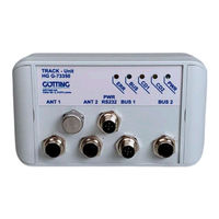
Gotting HG G-73350ZA Device Description (60 pages)
Interpreter for the Inductive Track For the connection of 2 antennas – Interfaces
Brand:
Gotting
| Category:
Microphone system
| Size: 1 MB
Table of Contents
Overview
3
Table of Contents
3
1 About this Document
5
Validity
5
Target Group
5
Other Applicable Documents
5
Declaration of Conformity (Only HG G-73350)
6
Presentation of Information
6
Warning Notices
6
Symbols
7
Table 1 Hazard Classification According to ANSI Z535.6-2006
7
2 Safety Instructions
8
Intended Use
8
Improper Use
8
Qualification of the Users
9
Operating Conditions
9
General Safety Instructions
10
Obligations of the Operator
10
3 Introduction
12
Variant Overview
12
System Components
12
Accessories
12
Table 2 Variant Overview
12
4 Mounting
14
Casing Dimensions
14
Connectors
14
Antenna Sockets on the Interpreter
14
Figure 1 Casing Dimensions Interpreter HG G-73350/HG G-73351
14
Table 3 Pin Allocation Antenna Sockets, Connectors ANT1 and ANT2
14
CAN Bus (HG G-73350)
15
Profibus (HG G-73351)
15
Table 4 Pin Allocation CAN Bus, Connectors BUS1 and BUS2
15
Table 5 Pin Allocation Profibus, Connectors BUS1 and BUS2
15
Power Supply and Serial Interface
16
Table 6 Pin Allocation of Power Supply and Serial Interface, Connector PWR / RS232
16
5 Commissioning
17
6 Hardware
18
Monitoring
18
Presettings
18
Processing the Signal
18
The Control Leds
19
CAN Bus (HG G-73350)
19
Profibus (HG G-73351)
19
Figure 2 Position of the Leds
19
7 Software
20
Connection to a PC Via the Serial Interface
20
Terminal Program
20
Monitor Program
20
Main Menu
20
Figure 3 Connection Example: Connection to the Serial Interface of a PC
20
Table 7 Transmission Parameters of the Serial RS 232 Interface
20
Figure 4 Screenshot: Main Menu of the Monitor Program (HG G-73350 with CAN Bus)
21
Figure 5 Screenshot: Main Menu of the Monitor Program (HG G-73351 with Profibus)
21
Table 8 Meaning of the Possible Values in the Status Output
22
Antenna Menu
23
Figure 6 Screenshot: Antenna Menu
23
CAN Menu (HG G-73350)
24
Figure 7 Screenshot: Calibration Menu Antenna 1
24
Figure 8 Screenshot: CAN Menu (HG G-73350)
24
Profibus Menu (HG G-73351)
26
Switching to Different Environment Parameters
26
Firmware-Update
26
Figure 9 Screenshot: Profibus-Menu (HG G-73351)
26
Figure 10 Screenshot: Firmware Update
27
Figure 11 Screenshot: Firmware Upload
27
8 CAN Interface (HG G-73350)
28
Definition of the Terms CAN and Canopen
28
Table 9 Parameters PDO Operation Mode
28
Table 10 PDO Operation Modes
28
Table 11 Definition of Terms Can/Canopen
29
Table 12 Bit and Byte Order
29
Table 13 Canopen® Operation States
29
Description of the Process Data Objects (Pdos)
30
Transmission Objects
30
Pdo_1
30
Table 14 CAN: Displayed Numbers for PDO_1
30
Table 15 CAN: Meaning of the Status Bits
30
Table 16 CAN: Calculation of Negative Deviation Values (Example: Maximum)
31
Table 17 CAN: Calculation of Positive Deviation Values (Example: Maximum)
31
Table 18 CAN: Deviation Value Output for Loss of Wire
31
Table 19 CAN: Example Values for the Deviation Value Output
31
Pdo_2
32
Receiving Objects
32
Table 20 CAN: Displayed Numbers for PDO_2
32
Table 21 Examples for the Conversion in PDO_2
32
Table 22 CAN: Displayed Numbers for RPDO
32
Heartbeat
33
Writing on Service Data Objects (Sdos)
33
Object Directory
33
Table 23 CAN: Heartbeat Device Statuses
33
Table 24 CAN: SDO Error Codes
33
Communication Specific Entries
34
Table 25 CAN: Overview of Object Directory, Communication Specific Entries Bet- Ween 0X1000 and 0X1Fff
34
Manufacturer Entries
35
Table 26 CAN: Overview of Object Directory, Manufacture Specific Entries from 0X2000 on
35
Standard Device Profile
36
Canopen Object Dictionary
36
Device Type
36
Error Register
36
Table 27 CAN: Overview Object Directory, Standardized Device Profile from 0X6000 on
36
Table 28 CAN: Device Type
36
Table 29 CAN: Error Register
36
COB-ID SYNC Message
37
Device Name
37
Hardware Version
37
Software Version
37
Save Parameter
37
Table 30 CAN: COB-ID SYNC Message
37
Table 31 CAN: Device Name
37
Table 32 CAN: Hardware Version
37
Table 33 CAN: Software Version
37
Table 34 CAN: Save Parameter
37
Restore Default Parameter
38
Producer Heartbeat Time
38
Identity Object
38
Table 35 CAN: Restore Default Parameter
38
Table 36 CAN: Producer Heartbeat Time
38
Table 37 CAN: Identity Object
38
Receive PDO Parameter
39
Mapping RPDO_1
39
Transmit PDO_1 Parameter
39
Table 38 CAN: Receive PDO Parameter
39
Table 39 CAN: Mapping RPDO_1
39
Table 40 CAN: Transmit PDO_1 Parameter
39
Transmit PDO_2 Parameter
40
Mapping Txpdo_1
40
Table 41 CAN: Transmit PDO_2 Parameter
40
Table 42 CAN: Mapping Txpdo_1
40
Mapping Txpdo_2
41
Manufacture Parameter - Parameters of the Antenna
41
Table 43 CAN: Mapping Txpdo_2
41
Table 44 CAN: Manufacture Parameter - Parameters of the Antenna
41
Manufacture Parameter - Calibration of the Antenna
42
Table 45 CAN: Manufacture Parameter - Calibration of the Antenna
42
Manufacture Parameter - Node Parameter
43
Bit Digital Input (Transmitted in Txpdo 1)
43
Table 47 CAN: Coding of the Node Baudrate
43
Table 48 CAN: Coding of the Node Config Byte
43
Table 46 CAN: Manufacture Parameter - Node Parameter
43
Table 49 CAN: 8 Bit Digital Input (Transmitted in Txpdo 1)
43
Bit Analog Inputs (Transmitted in Txpdo 1 und Txpdo 2)
44
Table 50 CAN: 16 Bit Analog Inputs (Transmitted in Txpdo 1 und Txpdo 2)
44
9 Profibus Interface (HG G-73351)
45
Table 51 Format of the 5 Profibus Input Bytes
45
Table 52 Profibus: Meaning of the Profibus Status Bits
45
Table 53 Profibus: Structure of the Profibus Output Bytes
45
10 Troubleshooting
46
Table 54 Troubleshooting
46
11 Technical Data
47
Table 55 Technical Data HG G-7335Xza
47
12 Appendix
48
Block Diagrams
48
Figure 12 Block Diagram HG G-73350 (CAN-Bus)
48
Figure 13 Block Diagram HG G-73351 (Profibus)
48
Diagrams
49
Figure 14 Frequency Response Interpreter HG G-73350ZA + Antenna HG G
49
Figure 15 Frequency Response Output Compensated)
49
Figure 16 Band Filter Characteristics at 5 Khz (Q=20)
50
Figure 17 Band Filter Characteristics at 10 Khz (Q=22)
50
Figure 18 Band Filter Characteristics at 15 Khz (Q=21)
51
Figure 19 Band Filter Characteristics at 20 Khz (Q=22)
51
Figure 20 Band Filter Characteristics at 25 Khz (Q=28)
51
Electronic Data Sheet (EDS File, HG G-73350)
52
GSD File (HG G-73351)
52
53 List of Figures
53
14 List of Tables
54
15 Index
56
16 Copyright and Terms of Liability
58
Copyright
58
Exclusion of Liability
58
Trade Marks and Company Names
58
Advertisement
Gotting HG G-73350ZA Manual (60 pages)
Interpreter for the Inductive Track Guidance of Vehicles for the Connection of 2 Antennas
Brand:
Gotting
| Category:
GPS
| Size: 2 MB
Table of Contents
Table of Contents
3
About this Document
5
Validity
5
Target Group
5
Other Applicable Documents
5
Declaration of Conformity (Only HG G-73350)
5
Presentation of Information
6
Warning Notices
6
Table 1 Hazard Classification According to ANSI Z535.6-2006
6
Symbols
7
Improper Use
8
Intended Use
8
Safety Instructions
8
Qualification of the Users
9
Operating Conditions
9
General Safety Instructions
10
Obligations of the Operator
10
Introduction
12
Variant Overview
12
System Components
12
Accessories
12
Table 2 Variant Overview
12
Figure 1 Casing Dimensions Interpreter HG G-73350/HG G-73351
14
Table 3 Pin Allocation Antenna Sockets, Connectors ANT1 and ANT2
14
Mounting
14
Antenna Sockets on the Interpreter
14
Casing Dimensions
14
Connectors
14
CAN Bus (HG G-73350)
15
Profibus (HG G-73351)
15
Table 4 Pin Allocation CAN Bus, Connectors BUS1 and BUS2
15
Table 5 Pin Allocation Profibus, Connectors BUS1 and BUS2
15
Power Supply and Serial Interface
16
Table 6 Pin Allocation of Power Supply and Serial Interface, Connector PWR / RS232
16
Commissioning
17
Processing the Signal
18
Hardware
18
Presettings
18
Monitoring
18
The Control Leds
19
CAN Bus (HG G-73350)
19
Profibus (HG G-73351)
19
Figure 2 Position of the Leds
19
Figure 3 Connection Example: Connection to the Serial Interface of a PC
20
Table 7 Transmission Parameters of the Serial RS 232 Interface
20
Software
20
Terminal Program
20
Connection to a PC Via the Serial Interface
20
Monitor Program
21
Main Menu
21
Figure 4 Screenshot: Main Menu of the Monitor Program (HG G-73350 with CAN Bus)
21
Figure 5 Screenshot: Main Menu of the Monitor Program (HG G-73351 with Profibus)
21
Table 8 Meaning of the Possible Values in the Status Output
22
Antenna Menu
23
Figure 6 Screenshot: Antenna Menu
23
Figure 8 Screenshot: CAN Menu (HG G-73350)
24
CAN Menu (HG G-73350)
24
Figure 7 Screenshot: Calibration Menu Antenna 1
24
Profibus Menu (HG G-73351)
26
Switching to Different Environment Parameters
26
Firmware-Update
26
Figure 9 Screenshot: Profibus-Menu (HG G-73351)
26
Figure 10 Screenshot: Firmware Update
27
Figure 11 Screenshot: Firmware Upload
27
Table 9 Parameters PDO Operation Mode
28
Definition of the Terms CAN and Canopen
28
CAN Interface (HG G-73350)
28
Table 10 PDO Operation Modes
29
Table 11 Definition of Terms Can/Canopen
29
Table 12 Bit and Byte Order
29
Table 13 Canopen® Operation States
29
Description of the Process Data Objects (Pdos)
30
Transmission Objects
30
Pdo_1
30
Table 14 CAN: Displayed Numbers for PDO_1
30
Table 15 CAN: Meaning of the Status Bits
30
Table 19 CAN: Example Values for the Deviation Value Output
31
Table 16 CAN: Calculation of Negative Deviation Values (Example: Maximum)
31
Table 18 CAN: Deviation Value Output for Loss of Wire
31
Table 17 CAN: Calculation of Positive Deviation Values (Example: Maximum)
31
Pdo_2
32
Receiving Objects
32
Table 20 CAN: Displayed Numbers for PDO_2
32
Table 21 Examples for the Conversion in PDO_2
32
Table 22 CAN: Displayed Numbers for RPDO
32
Table 23 CAN: Heartbeat Device Statuses
33
Table 24 CAN: SDO Error Codes
33
Heartbeat
33
Writing on Service Data Objects (Sdos)
33
Object Directory
33
Communication Specific Entries
34
Table 25 CAN: Overview of Object Directory, Communication Specific Entries Be- Tween 0X1000 and 0X1Fff
34
Manufacturer Entries
35
Table 26 CAN: Overview of Object Directory, Manufacture Specific Entries from 0X2000 on
35
Table 27 CAN: Overview Object Directory, Standardized Device Profile from 0X6000 on
36
Table 29 CAN: Error Register
36
Table 28 CAN: Device Type
36
Device Type
36
Error Register
36
Canopen Object Dictionary
36
Standard Device Profile
36
Table 30 CAN: COB-ID SYNC Message
37
Table 34 CAN: Save Parameter
37
Table 33 CAN: Software Version
37
Table 31 CAN: Device Name
37
Table 32 CAN: Hardware Version
37
Save Parameter
37
Hardware Version
37
Device Name
37
COB-ID SYNC Message
37
Software Version
37
Restore Default Parameter
38
Producer Heartbeat Time
38
Identity Object
38
Table 35 CAN: Restore Default Parameter
38
Table 36 CAN: Producer Heartbeat Time
38
Table 37 CAN: Identity Object
38
Table 39 CAN: Mapping RPDO_1
39
Table 40 CAN: Transmit PDO_1 Parameter
39
Receive PDO Parameter
39
Table 38 CAN: Receive PDO Parameter
39
Transmit PDO_1 Parameter
39
Mapping RPDO_1
39
Transmit PDO_2 Parameter
40
Mapping Txpdo_1
40
Table 41 CAN: Transmit PDO_2 Parameter
40
Table 42 CAN: Mapping Txpdo_1
40
Table 44 CAN: Manufacture Parameter - Parameters of the Antenna
41
Table 43 CAN: Mapping Txpdo_2
41
Manufacture Parameter - Parameters of the Antenna
41
Mapping Txpdo_2
41
Manufacture Parameter - Calibration of the Antenna
42
Table 45 CAN: Manufacture Parameter - Calibration of the Antenna
42
Manufacture Parameter - Node Parameter
43
Bit Digital Input (Transmitted in Txpdo 1)
43
Table 47 CAN: Coding of the Node Baudrate
43
Table 48 CAN: Coding of the Node Config Byte
43
Table 46 CAN: Manufacture Parameter - Node Parameter
43
Table 49 CAN: 8 Bit Digital Input (Transmitted in Txpdo 1)
43
Table 50 CAN: 16 Bit Analog Inputs (Transmitted in Txpdo 1 und Txpdo 2)
44
Bit Analog Inputs (Transmitted in Txpdo 1 und Txpdo 2)
44
Profibus Interface (HG G-73351)
45
Table 51 Format of the 5 Profibus Input Bytes
45
Table 52 Profibus: Meaning of the Profibus Status Bits
45
Table 53 Profibus: Structure of the Profibus Output Bytes
45
Troubleshooting
46
Table 54 Troubleshooting
46
Technical Data
47
Table 55 Technical Data HG G-7335Xzb
47
Figure 13 Block Diagram HG G-73351 (Profibus)
48
Appendix
48
Figure 12 Block Diagram HG G-73350 (CAN-Bus)
48
Block Diagrams
48
Diagrams
49
Figure 14 Frequency Response Interpreter HG G-73350 + Antenna HG G
49
Figure 15 Frequency Response Output Compensated)
49
Figure 16 Band Filter Characteristics at 5 Khz (Q=20)
50
Figure 17 Band Filter Characteristics at 10 Khz (Q=22)
50
Figure 20 Band Filter Characteristics at 25 Khz (Q=28)
51
Figure 19 Band Filter Characteristics at 20 Khz (Q=22)
51
Figure 18 Band Filter Characteristics at 15 Khz (Q=21)
51
Electronic Data Sheet (EDS File, HG G-73350)
52
GSD File (HG G-73351)
52
List of Figures - Chapter 13 53 List of Figures
53
List of Figures
53
List of Tables
54
Index
56
Copyright
58
Copyright and Terms of Liability
58
Exclusion of Liability
58
Trade Marks and Company Names
58
Advertisement
Related Products
Gotting HG G-73351ZA
Gotting HG 73350
Gotting HG G-7335xZA Series
Gotting HG G-73350ZB
Gotting HG G-73351ZB
Gotting HG G-73650ZD
Gotting HG G-71915ZA
Gotting HG G-19370ZA
Gotting HG G-98810ZC
Gotting HG G-98830YB
Gotting Categories
Antenna
GPS
Accessories
Controller
Marine Radio
More Gotting Manuals
Login
Sign In
OR
Sign in with Facebook
Sign in with Google
Upload manual
Upload from disk
Upload from URL