Gotting HG G-73650ZD Basics, Setup And Software
Navigation controller
Hide thumbs
Also See for HG G-73650ZD:
- Basics, setup and software (206 pages) ,
- Basics, setup and software (165 pages)

Related Manuals for Gotting HG G-73650ZD

Summary of Contents for Gotting HG G-73650ZD
- Page 1 Autonomous Vehicles Navigation Controller HG G-73650ZD Basics, Setup and Software English, Revision 05 Date: 09.03.2017 Dev. by: ML / LM Author(s): RAD / ML Innovation in Guidance www.goetting-agv.com...
- Page 2 Overview HG G-73650ZD ® 2017 Götting KG, errors and modifications reserved. The Götting KG in D-31275 Lehrte has a certified quality management system according to ISO 9001. Documentation HG G-73650ZD | English, Revision 05 | Date: 09.03.2017 | www.goetting-agv.com...
-
Page 3: Table Of Contents
Guidance of an omnidirectional Vehicle................30 2.6.4 Guidance of a non-omnidirectional Vehicle ................. 32 2.6.5 Driving Modes ..........................32 2.6.5.1 Idle Mode ............................. 33 2.6.5.2 Parameter Test Mode ......................33 Documentation HG G-73650ZD | English, Revision 05 | Date: 09.03.2017 | www.goetting-agv.com... - Page 4 Position ............................53 4.2.4.4 Diff. Data Age ..........................53 4.2.4.5 Satellites ............................53 4.2.4.6 Accuracy ............................53 4.2.4.7 Base Vector ..........................54 4.2.4.8 Heading ............................54 4.2.5 Error ..............................55 Documentation HG G-73650ZD | English, Revision 05 | Date: 09.03.2017 | www.goetting-agv.com...
- Page 5 Setting the parameters ....................87 5.4.1 Configuration -> Main ......................... 88 5.4.2 Configuration –> Guidance......................89 5.4.3 Configuration –> Wheels......................89 5.4.4 Configuration –> Antenna......................91 5.4.5 Configuration –> Accuracy ......................92 Documentation HG G-73650ZD | English, Revision 05 | Date: 09.03.2017 | www.goetting-agv.com...
- Page 6 Radius Calculation with 16 Bit Resolution ................145 Configuration of the Ethernet Interface Parameters via SIO 2 ........146 Firmware-Update via the USB Interface ................. 147 12 List of Figures ..................150 Documentation HG G-73650ZD | English, Revision 05 | Date: 09.03.2017 | www.goetting-agv.com...
- Page 7 13 List of Tables..................153 14 Copyright and Terms of Liability ............. 155 14.1 Copyright ......................... 155 14.2 Exclusion of Liability ....................155 14.3 Trade Marks and Company Names ................. 155 Documentation HG G-73650ZD | English, Revision 05 | Date: 09.03.2017 | www.goetting-agv.com...
-
Page 8: Introduction
Chapter 1: Introduction HG G-73650ZD Introduction The subject of this manual is the Navigation Controller HG G-73650ZD that enables AGV (Automated Guided Vehicles) to follow virtual tracks. The following terms are used synony- mously throughout this document: – Control Unit (as printed onto the hardware) –... -
Page 9: Tasks Of The Navigation Controller
(GPS e.g. is only suitable for outdoor envi- Documentation HG G-73650ZD | English, Revision 05 | Date: 09.03.2017 | www.goetting-agv.com... -
Page 10: Requirements / Options
If emergency stop functions are to be provided, a vehicle control system is manda- tory as the highest possible safety can only be achieved when both steering control- ler and vehicle control system are installed. Documentation HG G-73650ZD | English, Revision 05 | Date: 09.03.2017 | www.goetting-agv.com... -
Page 11: Basic Principles Of Track Guidance
Sketch: Suitable vehicle types Figure 2 Documentation HG G-73650ZD | English, Revision 05 | Date: 09.03.2017 | www.goetting-agv.com... -
Page 12: System Composition
CAN bus. Additionally their posi pulse has to be connected with IO-3 (see manual of the antenna). The optional Gyro is connected via CAN bus as well and is intended to enhance the odometry. Documentation HG G-73650ZD | English, Revision 05 | Date: 09.03.2017 | www.goetting-agv.com... -
Page 13: The Odometry
±125 and up to ± 500mm, the read- ing distance varies between 50 - 200 mm. Possible antennas are e.g. the Götting types HG 98810, HG 98820 and HG 98850. Documentation HG G-73650ZD | English, Revision 05 | Date: 09.03.2017 | www.goetting-agv.com... -
Page 14: Single Antenna Evaluation - Calculation Of The Position With One Antenna
Front Vehicle X Single antenna: Placement Figure 5 ATTENTION! In order to be able to calculate a position it is normally necessary to detect more than one transponder! Documentation HG G-73650ZD | English, Revision 05 | Date: 09.03.2017 | www.goetting-agv.com... -
Page 15: Figure 6 Properties Of A Single Antenna Set-Up
The green area is the reception area of the transponder antenna (here approx. ±50 mm x ±125 mm) If the thicker red line in the center of the antenna is crossed by a transponder, a posi pulse will be triggered. Documentation HG G-73650ZD | English, Revision 05 | Date: 09.03.2017 | www.goetting-agv.com... -
Page 16: Double Antenna Evaluation
(posi pulse of the transponder). 2.3.2.1.2 Double Antenna Evaluation Front Vehicle Y Antenna 1 Antenna 3 Vehicle X Properties of a double antenna set-up Figure 7 Documentation HG G-73650ZD | English, Revision 05 | Date: 09.03.2017 | www.goetting-agv.com... -
Page 17: The Triple Antenna Evaluation
After the third transponder the position is confirmed and the accuracy is set to a good value provided the relative position of the third Transponder corresponds with the positions of the previous ones. Documentation HG G-73650ZD | English, Revision 05 | Date: 09.03.2017 | www.goetting-agv.com... -
Page 18: The Transponder List
1/100°. Attribute 2 and attribute 3 are currently unused. Attribute 4 indi- cates a start transponder with a 1. 2.3.2.2 GPS Currently positioning with GPS has not yet been implemented, but will be available at a later date. Documentation HG G-73650ZD | English, Revision 05 | Date: 09.03.2017 | www.goetting-agv.com... -
Page 19: Coordinate Systems
When the GPS system is used either a local base station (origin) or the country coor- dinate system are used. If no local base station is used the necessary GPS correction data (wireless) have to be leased from a local provider. Documentation HG G-73650ZD | English, Revision 05 | Date: 09.03.2017 | www.goetting-agv.com... -
Page 20: Characteristics Of The Coordinate Systems
The base station then marks the origin. This still results in projection errors. Continental drift is no longer an issue since the base station drifts with the land masses. Documentation HG G-73650ZD | English, Revision 05 | Date: 09.03.2017 | www.goetting-agv.com... -
Page 21: Reconstruction Of The Route (Segments)
However if the distances between the points are too big, the CAD program would display them as angular curves because then no curved routes can be calculated from points which are wide apart from each other. Documentation HG G-73650ZD | English, Revision 05 | Date: 09.03.2017 | www.goetting-agv.com... -
Page 22: The Segment File
0x00000001 9000 10000 500 0x00000000 9000 10000 1000 0x00000000 9000 10000 1500 0x00000000 9000 10000 2000 0x00000002 9000 Structure of a segment file with support points Table 2 Documentation HG G-73650ZD | English, Revision 05 | Date: 09.03.2017 | www.goetting-agv.com... -
Page 23: The Segment Search
(as described in the following section this process usually runs automat- ically in the background). During the segment search, the navigation controller tests all the segments stored for drivability. The segment search can take several seconds depending on Documentation HG G-73650ZD | English, Revision 05 | Date: 09.03.2017 | www.goetting-agv.com... -
Page 24: Selection Of Segments
Support Point Segment Support Point Segment Segment Segment FIFO Track shifting register Segment Segment Segment Segment Segment Segment Segments to be driven Segment Segment FIFO shifting register Figure 14 Documentation HG G-73650ZD | English, Revision 05 | Date: 09.03.2017 | www.goetting-agv.com... -
Page 25: Transmission Of Segmente
(Position of segment number in table). The navigation controller will be called up every 10 ms. Therefore the transmission of the list takes at least 8 x 10ms = 80 ms. This list always Documentation HG G-73650ZD | English, Revision 05 | Date: 09.03.2017 | www.goetting-agv.com... -
Page 26: Attributes
Segment 4 is the return from the right offset to the actual course. Segment 3 (dispel offset left) Segment 1 (establish offset left) Neutral line Segment 2 (establish offset right) Segment 4 (dispel offset right) Offset segments Figure 15 Documentation HG G-73650ZD | English, Revision 05 | Date: 09.03.2017 | www.goetting-agv.com... -
Page 27: Inverted Steering
(steer right in right turn) Wheel heading and max. steering angle „Steer inverse“ The curve can be driven (steer left Initial position in right turn) Example: Inverted steering Figure 17 Documentation HG G-73650ZD | English, Revision 05 | Date: 09.03.2017 | www.goetting-agv.com... -
Page 28: Stop Distance
This e.g. allows the PLC to read connected light barriers so that it can stop the vehicle with „Clearance segment“. Documentation HG G-73650ZD | English, Revision 05 | Date: 09.03.2017 | www.goetting-agv.com... -
Page 29: Spot Turn
Additionally the CSV files can be directly read, processed and exported using the easy-to- use Online Track Editor of Götting. The Track Editor is available at the following address: Link http://www.goetting.de/trackeditor Documentation HG G-73650ZD | English, Revision 05 | Date: 09.03.2017 | www.goetting-agv.com... -
Page 30: Figure 19 Online Track Editor By Götting
Chapter 2: Basic Principles of Track Guidance HG G-73650ZD Online Track Editor by Götting Figure 19 Documentation HG G-73650ZD | English, Revision 05 | Date: 09.03.2017 | www.goetting-agv.com... -
Page 31: Track Guidance
(it forms what are known as regressions) and thus constructs the virtual track that the vehicle is to be driven on. The tracks between the support points are reconstructed Documentation HG G-73650ZD | English, Revision 05 | Date: 09.03.2017 | www.goetting-agv.com... -
Page 32: Speed Calculation
Forward Dis. Var Forward Dis. Fix Forward Dis. Fix Forward Dis. Var Target Position Deviation Rear Segment Direction Rear Direction Virtual Point Rear Guidance of an omnidirectional vehicle Figure 21 Documentation HG G-73650ZD | English, Revision 05 | Date: 09.03.2017 | www.goetting-agv.com... -
Page 33: Figure 22 Guiding An Omnidirectional Vehicle: Control Process
Approach Lim. Var Approach Lim. Fix - - - - - - - - - - - - - Formula: Limitation of angles Figure 23 Documentation HG G-73650ZD | English, Revision 05 | Date: 09.03.2017 | www.goetting-agv.com... -
Page 34: Guidance Of A Non-Omnidirectional Vehicle
(see section 2.6.5.4). Vector steering, in this mode the vehicle drives to the target on a straight line (see section 2.6.5.5). Documentation HG G-73650ZD | English, Revision 05 | Date: 09.03.2017 | www.goetting-agv.com... -
Page 35: Idle Mode
Remote Mode = 3: Dog tracking forward, Remote X determines the speed in mm/s in the vehicle's longitudinal direction, Remote Y the steering angle for all wheels in 1/ . Remote Z has no function. Documentation HG G-73650ZD | English, Revision 05 | Date: 09.03.2017 | www.goetting-agv.com... -
Page 36: Vector Steering Mode
PLC adapts the navigation controller to the vehicle. This offers the advantage of a standard interface. The customer can directly affect the adaptation and is therefore able to Documentation HG G-73650ZD | English, Revision 05 | Date: 09.03.2017 | www.goetting-agv.com... - Page 37 Four IO channels are available as well. Their configuration depends on the set vehicle op- tion. For most vehicle options IO 1 - IO3 stand for the Posi Pulse inputs from the transponder antennas and IO4 for the emergency stop output. Documentation HG G-73650ZD | English, Revision 05 | Date: 09.03.2017 | www.goetting-agv.com...
-
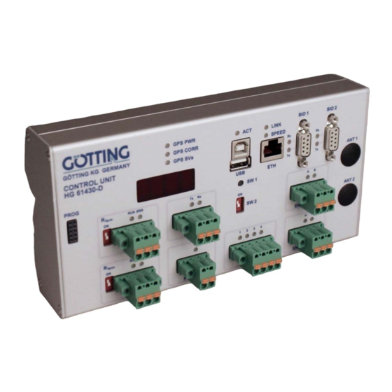
Page 38: Hardware
HG G-61431ZA for Profinet (Feldbus) and with option GPS Photo of the Control Unit: Basic configuration and version including the Feldbus/Profinet ex- Figure 26 tension module and with option GPS Documentation HG G-73650ZD | English, Revision 05 | Date: 09.03.2017 | www.goetting-agv.com... -
Page 39: Mounting
SW 2 Firmware Update via USB interface Normal operation of the control unit Control elements of the control unit (part 1 of 2) Table 5 Documentation HG G-73650ZD | English, Revision 05 | Date: 09.03.2017 | www.goetting-agv.com... -
Page 40: Display Elements On Front Panel
Input/Output 4 signal > programmed threshold Display elements Table 6 3.5 Connectors 3.5.1 ETH Sketch of connector ETH Figure 29 Function: Communication with higher-level control and/or PC Interface: Ethernet Plug type: RJ-45 Documentation HG G-73650ZD | English, Revision 05 | Date: 09.03.2017 | www.goetting-agv.com... -
Page 41: Usb
Function: Configuration of Ethernet Interface, see section C on page 146 in the appendix Interface: RS 232 Plug type: Sub-D 9 pin (DE9) female Function Direction Pin assignment SIO 2 (part 1 of 2) Table 8 Documentation HG G-73650ZD | English, Revision 05 | Date: 09.03.2017 | www.goetting-agv.com... -
Page 42: Can 1
3.5.7 SIO 3 Sketch of connector SIO 3 Figure 35 Function: Not used Interface: RS 232 Plug type: Phoenix-Contact FKCT 2,5/3-STF-5,08 Function Direction Pin assignment SIO 2 Table 11 Documentation HG G-73650ZD | English, Revision 05 | Date: 09.03.2017 | www.goetting-agv.com... -
Page 43: Power
Interface: Switching threshold 5 - 24 Volt (configurable) Plug type: Phoenix-Contact FKCT 2,5/3-STF-5,08 Function Direction Kanal A Kanal B Pin assignment ENCODER 1 / ENCODER 2 Table 14 Documentation HG G-73650ZD | English, Revision 05 | Date: 09.03.2017 | www.goetting-agv.com... -
Page 44: Prog
The control unit can be ordered with the following field bus options: – HG G-61431ZA Profinet – HG G-61431YA Profibus Dimensions control unit incl. expansion module Figure 40 Documentation HG G-73650ZD | English, Revision 05 | Date: 09.03.2017 | www.goetting-agv.com... -
Page 45: Software
- with safety devices such as emergency off within reach, as the connection to the browser can be cut off and the vehicle can then no longer be stopped using the browser. Documentation HG G-73650ZD | English, Revision 05 | Date: 09.03.2017 | www.goetting-agv.com... -
Page 46: Main Menu
More information in the section entitled 'Transponder Table': Display of the transponders stored in the navigation controller. More informa- tion in section 4.10 on page 83. Documentation HG G-73650ZD | English, Revision 05 | Date: 09.03.2017 | www.goetting-agv.com... -
Page 47: Status Menu
Speed 2: Speed of wheel 2 – Speed 3: Speed of wheel 3 – Speed 4: Speed of wheel 4 – Angle 1: Steering angle of wheel 1 Documentation HG G-73650ZD | English, Revision 05 | Date: 09.03.2017 | www.goetting-agv.com... -
Page 48: Deviation
– Seg 1-8: segments 4.2.1.4 Segment This table shows information on the segment currently being driven Actual Seg 1. The dis- play is only current during automatic mode. Documentation HG G-73650ZD | English, Revision 05 | Date: 09.03.2017 | www.goetting-agv.com... -
Page 49: Plc
The following values are output: – Mode: Mode in which the navigation controller is currently operating. Three modes can be displayed: – Idle: The vehicle is not steered by the navigation controller Documentation HG G-73650ZD | English, Revision 05 | Date: 09.03.2017 | www.goetting-agv.com... -
Page 50: Transponder Menu
Here are only the most important bits (for more details, refer to the documentation of the transponder antennas that are deployed): – 0x0200: Transponder in the field – 0x0400: Transponder is decoded Documentation HG G-73650ZD | English, Revision 05 | Date: 09.03.2017 | www.goetting-agv.com... -
Page 51: Result
X Pos: X position of the vehicle in the global co-ordinate system. – Y Pos: Y position of the vehicle in the global co-ordinate system. – Distance: Distance driven since the last position calculation. Documentation HG G-73650ZD | English, Revision 05 | Date: 09.03.2017 | www.goetting-agv.com... -
Page 52: Gps
The position buffer fills up with 4 positions before a direction of movement can be calculated. If there is a switch from forwards to reverse, the buffer is reset. Documentation HG G-73650ZD | English, Revision 05 | Date: 09.03.2017 | www.goetting-agv.com... -
Page 53: Ons
3rd column: Unit of the value The following values are displayed: – Correction Heading Correction value for the angle – Correction Pos X Correction value for the X co-ordinate Documentation HG G-73650ZD | English, Revision 05 | Date: 09.03.2017 | www.goetting-agv.com... -
Page 54: Status
– SF GPS Error Error in the GPS system. These are only adopted into the error list of the navigation controller of the vehicle is travelling using GPS. Documentation HG G-73650ZD | English, Revision 05 | Date: 09.03.2017 | www.goetting-agv.com... -
Page 55: Gps Receiver
Geographical length (reference system WGS 84) 4.2.4.4 Diff. Data Age Age of the correction data 4.2.4.5 Satellites Number of satellites used 4.2.4.6 Accuracy Accuracy of the calculated position Documentation HG G-73650ZD | English, Revision 05 | Date: 09.03.2017 | www.goetting-agv.com... -
Page 56: Base Vector
MSEP Distance between the two GPS antennas – State State of the angle calculation – Tilt Inclination – Shift Tilt Shift of the position due to the inclination Documentation HG G-73650ZD | English, Revision 05 | Date: 09.03.2017 | www.goetting-agv.com... -
Page 57: Error
1. The Byte 2: Devices table in the line Wheels and column 2 contains 0x0040 which means that wheel 2 has a steering angle error. A more detailed example can be found in section 6.2.4 on page 107. Documentation HG G-73650ZD | English, Revision 05 | Date: 09.03.2017 | www.goetting-agv.com... -
Page 58: Tcp
To change the values, the password must be entered beforehand and confirmed with the Authenticate button. The nav- 314159 igation controller must also be in the Idle status. Documentation HG G-73650ZD | English, Revision 05 | Date: 09.03.2017 | www.goetting-agv.com... -
Page 59: Configuration -> Main
CAN1 Baudrate: Baud rate of the CAN bus 1. Normally, 250 or 500 kBit/s is used. – CAN2 Protocol: Not yet used – CAN2 Baudrate: Baud rate of the CAN bus 2. Normally, 250 or 500 kBit/s is used. Documentation HG G-73650ZD | English, Revision 05 | Date: 09.03.2017 | www.goetting-agv.com... - Page 60 Day: Specified day for the log file. – Hour: Specified hour for the log file. – Minute: Specified minute for the log file. – Second: Specified second for the log file. Documentation HG G-73650ZD | English, Revision 05 | Date: 09.03.2017 | www.goetting-agv.com...
-
Page 61: Configuration -> Guidance
4.3.3 Wheels The parameters for the geometry of the vehicle are set in this menu. Before you set the first values, you have to consider the following fundamental settings: Documentation HG G-73650ZD | English, Revision 05 | Date: 09.03.2017 | www.goetting-agv.com... -
Page 62: What Type Of Vehicle Is Involved
(wheel of the type Fix. Angle so that the navigation controller applies the corresponding controller). The vehicle zero point must be located on the virtual rigid axle. Documentation HG G-73650ZD | English, Revision 05 | Date: 09.03.2017 | www.goetting-agv.com... -
Page 63: The Omnidirectional Vehicle
The angles in X direction are 0 and become more positive with rotation to the left. Specification of the position data to be determined for a vehicle Figure 53 Documentation HG G-73650ZD | English, Revision 05 | Date: 09.03.2017 | www.goetting-agv.com... -
Page 64: Configuration -> Wheels
Contelec 1 Inv., for the event that the sensor is on its head, i.e. is inverted – Contelec 2, absolute angle sensor made by Contelec, address 418 (0x1A2), node number 22, always bus 2 Documentation HG G-73650ZD | English, Revision 05 | Date: 09.03.2017 | www.goetting-agv.com... - Page 65 If a speed is transferred, this parameter is not used. – Clearance: (not yet available) – Tolerance Angle: Tolerance of monitoring the steering angle of the corresponding wheel Documentation HG G-73650ZD | English, Revision 05 | Date: 09.03.2017 | www.goetting-agv.com...
-
Page 66: Configuration -> Antennas
Item: Shows which value is involved. Ant 1 to 4: Input of the values (4th antenna preparation for future applications) Unit: Unit of the value The following values can be changed: Documentation HG G-73650ZD | English, Revision 05 | Date: 09.03.2017 | www.goetting-agv.com... -
Page 67: Configuration -> Accuracy
(Virtual Point Front / Rear, see Figure 57 below) is measured in X and Y direc- tions of the vehicle coordinate system (Deviation Front / Rear). It is also measured in the centre of the vehicle in the lateral direction. Documentation HG G-73650ZD | English, Revision 05 | Date: 09.03.2017 | www.goetting-agv.com... -
Page 68: Configuration -> Steer Controller
Forward Dis. Var Forward Dis. Fix Forward Dis. Fix Forward Dis. Var Target Position Deviation Rear Segment Direction Rear Direction Virtual Point Rear Control of an omnidirectional vehicle Figure 57 Documentation HG G-73650ZD | English, Revision 05 | Date: 09.03.2017 | www.goetting-agv.com... -
Page 69: Figure 58 Screenshot: Configuration -> Steer Controller
'Parameter Test' menu. The angle increments are displayed in degrees/second. – Speed Spot Turn: Speed of the fastest wheel during a spot turn. Documentation HG G-73650ZD | English, Revision 05 | Date: 09.03.2017 | www.goetting-agv.com... -
Page 70: Configuration -> Speed Controller
Deviations of the control, how- ever, cannot be predicted. 4.3.7 Configuration –> Speed Controller Screenshot: Configuration –> Speed Controller Figure 60 Documentation HG G-73650ZD | English, Revision 05 | Date: 09.03.2017 | www.goetting-agv.com... -
Page 71: Configuration -> Sensor Fusion Transponder
4.3.8 Configuration –> Sensor Fusion Transponder Screenshot: Configuration –> Sensor Fusion Transponder Figure 61 The table has three columns: Item: Shows which value is involved. Setting: Input of the values Documentation HG G-73650ZD | English, Revision 05 | Date: 09.03.2017 | www.goetting-agv.com... -
Page 72: Configuration -> Sensor Fusion Gps
Instead, an odometry is corrected with the help of the GPS positions. The correction takes place by means of controllers that minimise the error be- Documentation HG G-73650ZD | English, Revision 05 | Date: 09.03.2017 | www.goetting-agv.com... -
Page 73: Figure 62 Screenshot: Configuration -> Sensor Fusion Gps
Antenna offset X: X position of the GPS antenna 1 with relation to the vehicle co-ordi- nate system. – Antenna offset Y: Y position of the GPS antenna 1 with relation to the vehicle co-ordi- nate system. Documentation HG G-73650ZD | English, Revision 05 | Date: 09.03.2017 | www.goetting-agv.com... - Page 74 – Transform Y Co-ordinate: Y offset from the zero point of the national co-ordinate sys- tem for the area to be travelled. Documentation HG G-73650ZD | English, Revision 05 | Date: 09.03.2017 | www.goetting-agv.com...
-
Page 75: Configuration -> Gyro
– Averaging Duration: If the 'Averaging Acknowledge' parameter is not enabled, the minimum averaging time is specified. It should not be below 5 seconds (the longer the better). Documentation HG G-73650ZD | English, Revision 05 | Date: 09.03.2017 | www.goetting-agv.com... -
Page 76: Configuration -> Servo
(servos), in which case the following settings must be made. This requires knowl- edge of automatic control engineering. Where servos are deployed, Götting KG commis- sioning support subject to charges is recommended. Documentation HG G-73650ZD | English, Revision 05 | Date: 09.03.2017 | www.goetting-agv.com... -
Page 77: Figure 65 Formula: Actuating Variable Calculation With Controller Boost
V Comp: Pre-control of the actuating variable (some motors need a minimum speed to start up; to activate this clockwise or anticlockwise running, a minimum speed can be specified here) Documentation HG G-73650ZD | English, Revision 05 | Date: 09.03.2017 | www.goetting-agv.com... -
Page 78: Network Menu
Setting: Input of the values Local network settings for the Ethernet interface of the navigation controller hardware HG 61430 for connection of a PC (see 3.5.1 on page 38). Documentation HG G-73650ZD | English, Revision 05 | Date: 09.03.2017 | www.goetting-agv.com... -
Page 79: Config File Menu
In that case, they can either be reloaded from an already saved parameter file or they have to be entered again. It is therefore recommended to back up the parameters saved on the navigation controller beforehand on the PC (see below). Documentation HG G-73650ZD | English, Revision 05 | Date: 09.03.2017 | www.goetting-agv.com... -
Page 80: Download -> Transfer Parameters From Navigation Controller Into A File On The Pc
Use the Select File button to select the segment file on the hard disk. ATTENTION! The name of the segment file must start with segmente, e.g. segmente_01.csv. Documentation HG G-73650ZD | English, Revision 05 | Date: 09.03.2017 | www.goetting-agv.com... -
Page 81: Download Segment File -> Transfer Segment File From The Navigation Controller Into A File On The Pc
'Download' folder without a prompt. As default, the file will have the name segment.csv, no matter what the name of the file was that was transferred into the naviga- tion controller. Documentation HG G-73650ZD | English, Revision 05 | Date: 09.03.2017 | www.goetting-agv.com... -
Page 82: Segment Table Menu
– Speed: Speed of the segment at the start (green) / end point (blue). – Attribute: Attributes of the segment at the start (green) / end point (blue). Documentation HG G-73650ZD | English, Revision 05 | Date: 09.03.2017 | www.goetting-agv.com... -
Page 83: Transponder File Menu
If a file with the name 'transponder…' is transferred and this file contains no transponders, the transponders stored in the navigation controller are lost. Documentation HG G-73650ZD | English, Revision 05 | Date: 09.03.2017 | www.goetting-agv.com... -
Page 84: Download Segment File -> Transfer Transponder File From The Navigation Controller Into A File On The Pc
Attrib. 1: Attribute 1 of the transponder, e.g. starting angle of a start transponder (see Transponder 39, see Figure 71) – Attrib. 2: Attribute 2 of the transponder. – Attrib. 3: Attribute 3 of the transponder. Documentation HG G-73650ZD | English, Revision 05 | Date: 09.03.2017 | www.goetting-agv.com... -
Page 85: Parameter Test' Menu
4.10.1 Requirements for switching into the different modes It is always possible to switch to 'Idle' It is possible to switch to 'Test' when the vehicle is at a standstill. Documentation HG G-73650ZD | English, Revision 05 | Date: 09.03.2017 | www.goetting-agv.com... -
Page 86: Possibilities In The 'Idle' Mode
(Test: 21 segments) is then loaded into the list of target segments as if they came from the vehicle control system. The above screenshot shows that the first 17 segments have been entered. Unused segments must be filled with the value 65535. Documentation HG G-73650ZD | English, Revision 05 | Date: 09.03.2017 | www.goetting-agv.com... -
Page 87: Setting A Starting Position
If the navigation controller is in the Idle mode, the current position can be set to another po- sition. The corresponding values must be entered in the table set Pos. Clicking the 'OK' but- ton adopts then these into the current actual position. Documentation HG G-73650ZD | English, Revision 05 | Date: 09.03.2017 | www.goetting-agv.com... -
Page 88: Commissioning
If a vehicle control system is present, the communication and segments can be tested using the simulation. Real operation: The vehicle is subsequently put into operation. Documentation HG G-73650ZD | English, Revision 05 | Date: 09.03.2017 | www.goetting-agv.com... -
Page 89: Commissioning The Communication
Every time a parameter is changed on a configuration page, the OK button in the interface should be actuated so that the new parameters are saved permanently in the navigation controller. Then, enter the following values in the corresponding configuration menus. Documentation HG G-73650ZD | English, Revision 05 | Date: 09.03.2017 | www.goetting-agv.com... -
Page 90: Configuration -> Main
USB stick Month Current month Current day Hour Current hour Minute Current minutes Second Current second Example commissioning parameters in Config. Main Table 15 Documentation HG G-73650ZD | English, Revision 05 | Date: 09.03.2017 | www.goetting-agv.com... -
Page 91: Configuration -> Guidance
0° and 360°. The steering angles move between -180° and +180°. If the vehicle moves in a forward direction, a wheel with the steering angle 0° must indicate a positive speed. Documentation HG G-73650ZD | English, Revision 05 | Date: 09.03.2017 | www.goetting-agv.com... -
Page 92: Table 17 Example Commissioning Parameters In Config. Wheels: Wheel 1
CAN ID Rx Is not used CAN ID Tx V Virtual actual steering angle and speed, not sent at 0. Example commissioning parameters in Config. Wheels: Wheel 2 Table 18 Documentation HG G-73650ZD | English, Revision 05 | Date: 09.03.2017 | www.goetting-agv.com... -
Page 93: Configuration -> Antenna
The position of the antennas of this vehicle is a negative example, because the antenna is very far from the fixed castors and thus from the symmetry axis (see section 2.3.2.1.1 on page 12). Documentation HG G-73650ZD | English, Revision 05 | Date: 09.03.2017 | www.goetting-agv.com... -
Page 94: Configuration -> Accuracy
Initially, 10 % of the final speed from the segment should be enough. This can be increased as commissioning progresses. Example commissioning parameters in Config. Speed Controller Table 23 Documentation HG G-73650ZD | English, Revision 05 | Date: 09.03.2017 | www.goetting-agv.com... -
Page 95: Configuration -> Sensor Fusion
Example commissioning parameters in Config. Gyro Table 25 Other settings directly in the gyroscope: – The gyroscope should transmit every 10 ms Documentation HG G-73650ZD | English, Revision 05 | Date: 09.03.2017 | www.goetting-agv.com... -
Page 96: Configuration -> Gps
Before the segment file can be transferred, the password must be entered. For the transfer, click on the 'Segment File' button and select the 314159 Documentation HG G-73650ZD | English, Revision 05 | Date: 09.03.2017 | www.goetting-agv.com... -
Page 97: Simulation Without Vehicle And Vehicle Controller
Optionally, the enable Loop button can be used to switch the list into an endless loop of the segments. Auto switches the navigation controller back into the automatic mode. Start the simulation with enable Release. Documentation HG G-73650ZD | English, Revision 05 | Date: 09.03.2017 | www.goetting-agv.com... -
Page 98: Simulation Without Vehicle And With Vehicle Controller
Most important here is the setting of the zero angle. Where possible, this angle should be set at the sensor or mechanically. If this does not work, the parameter Documentation HG G-73650ZD | English, Revision 05 | Date: 09.03.2017 | www.goetting-agv.com... -
Page 99: Figure 74 Formula: Correction Of 'Increment / Metres
'Status Transponder' menu at 'Tr Pos X' and 'Tr Pos Y'. Otherwise, check / re-transfer the transponder list in the 'Transponder Table' menu Documentation HG G-73650ZD | English, Revision 05 | Date: 09.03.2017 | www.goetting-agv.com... -
Page 100: Figure 75 Test Run 1 At Two Transponders
; X Pos: approx. +2.0 m; Y Pos: approx. - 0.05 m; Distance: approx. Antenna X Position Wheel 2 20dez positive vehicle angle 10dez Transponder Wheel 1 Test run 2 at two transponders Figure 76 Documentation HG G-73650ZD | English, Revision 05 | Date: 09.03.2017 | www.goetting-agv.com... - Page 101 'PLC' table. If the segment release is then set in the CAN Box Path data (target) in the byte Commands for vehicle guidance, the vehicle travels the segment provided no errors are pending. Documentation HG G-73650ZD | English, Revision 05 | Date: 09.03.2017 | www.goetting-agv.com...
-
Page 102: Other Optimisations
10 cm error: Set the parameter Deviation Attribute 1 to 15 cm and the parameter Deviation Attribute 0 to 6 cm. With the accuracy, proceed in the same way. Documentation HG G-73650ZD | English, Revision 05 | Date: 09.03.2017 | www.goetting-agv.com... -
Page 103: Optimising The Steering Controller
Documentation HG G-73650ZD | English, Revision 05 | Date: 09.03.2017 | www.goetting-agv.com... -
Page 104: Optimising The Speed Ramps
If the vehicle is unable to follow the speed required by the segments, there is a danger that at the end of the segment it brakes beyond the end of the segment. Documentation HG G-73650ZD | English, Revision 05 | Date: 09.03.2017 | www.goetting-agv.com... -
Page 105: Can Bus Protocol
PLC only has access to the PLC Tx buffer. The transmission routine sends via the Tx Buffer according to the state machine shown below. After index 7 of the Tx Buffer is sent, it copies the PLC Tx buffer into the Tx buffer. Documentation HG G-73650ZD | English, Revision 05 | Date: 09.03.2017 | www.goetting-agv.com... -
Page 106: Figure 80 State Machine Segment Transmission Via Can Buffers
Tx Buffer = 7? Copy PLC Tx Buffer into Tx Buffer Step Go to Step 1 State machine segment transmission via CAN buffers Figure 80 Documentation HG G-73650ZD | English, Revision 05 | Date: 09.03.2017 | www.goetting-agv.com... -
Page 107: Transmission Telegrams From Control Unit To Plc, The Wheels And The Gyro
– Instead of Actual Point Number: Distance traveled since mode start. – Instead of Max Point Number: Distance until the target. The distances are limited to 32 m. CAN Tx Telegram: Path data (actual) Table 26 Documentation HG G-73650ZD | English, Revision 05 | Date: 09.03.2017 | www.goetting-agv.com... -
Page 108: Segment Search Box
5 – byte 6 – byte 7 Message-Counter The Message-Counter will be increased with each trans- mission as sign of operation. CAN Rx Telegram: Status Box Table 28 Documentation HG G-73650ZD | English, Revision 05 | Date: 09.03.2017 | www.goetting-agv.com... -
Page 109: Error Box
When there are several Errors they are sent in ascending order. As soon as the Error Number decreases in between two telegrams a new sequence begins, The following image shows the corresponding sequence for the example above: Documentation HG G-73650ZD | English, Revision 05 | Date: 09.03.2017 | www.goetting-agv.com... -
Page 110: Figure 81 Can Error Telegram Transmission/Synchronization Sequence
Request Count 3 (11) & Object No. (Rad 3) answered with 0x10 Error Number 16 Wheels Request Count Error Number decreases = new sequence starts CAN Error telegram transmission/synchronization sequence Figure 81 Documentation HG G-73650ZD | English, Revision 05 | Date: 09.03.2017 | www.goetting-agv.com... -
Page 111: Table 29 Can Telegram: Error
7 – Error Number (0-31) from the bytes 0-3 above / vehicle stops – Warning Numbers (> 31, s. Table 30) / vehi- cle continues operation CAN Telegram: Error Table 29 Documentation HG G-73650ZD | English, Revision 05 | Date: 09.03.2017 | www.goetting-agv.com... -
Page 112: Table 30 Can Error Codes
0x0002 Gyro is compensating the drift – 0x0001 Error PLC receive 0x0002 Error PLC receive (according to old communication) CAN Error Codes (part 1 of 2) Table 30 Documentation HG G-73650ZD | English, Revision 05 | Date: 09.03.2017 | www.goetting-agv.com... -
Page 113: Wheel Boxes
CAN Tx Telegram: Wheel Tx Table 31 Command Bit 0..12 not used Bit 13 Steering enable Bit 14 Driving enable Bit 15 Toggle Wheel Tx Command Bits Table 32 Documentation HG G-73650ZD | English, Revision 05 | Date: 09.03.2017 | www.goetting-agv.com... -
Page 114: Table 33 Can Tx Telegram: Wheel Tx Virtual
Highbyte Command (s. Table 34 below) CAN Tx Telegram: Wheel Tx Virtual Table 33 Command Bit 0 0: not inverted 1: inverted Wheel Tx Virtual Command Bits Table 34 Documentation HG G-73650ZD | English, Revision 05 | Date: 09.03.2017 | www.goetting-agv.com... -
Page 115: Gyro Box
Bit 1: Angle reset byte 1 – byte 2 – byte 3 – byte 4 – byte 5 – byte 6 – byte 7 – CAN Tx Telegram: Gyro Table 35 Documentation HG G-73650ZD | English, Revision 05 | Date: 09.03.2017 | www.goetting-agv.com... -
Page 116: Reception Telegrams From Plc, Wheels, Antennas, Gyro And Sensor Fusion To The Control Unit
Highbyte of segment (table) byte 6 Index number of table (0-7) in normal mode byte 7 Request Count of Segments CAN Rx Telegram: Path data (target) Table 36 Documentation HG G-73650ZD | English, Revision 05 | Date: 09.03.2017 | www.goetting-agv.com... -
Page 117: Sps Control Box
Each emergency stop means that the wheels might have blocked which leads to a less accurate position calculation! CAN Rx Telegram: Control Box Table 37 Documentation HG G-73650ZD | English, Revision 05 | Date: 09.03.2017 | www.goetting-agv.com... -
Page 118: Remote Control Box
6 Highbyte Remote Z byte 7 Message-Counter The Message-Counter will be increased with each trans- mission as sign of operation. CAN Rx Telegram: Remote Control Table 38 Documentation HG G-73650ZD | English, Revision 05 | Date: 09.03.2017 | www.goetting-agv.com... -
Page 119: Wheel Box
Antenna Code byte 5 Antenna Code High byte 6 Antenna Deviation Low byte 7 Antenna Deviation High CAN Rx Telegram: Antenna 1 Status, Code and Deviation Table 41 Documentation HG G-73650ZD | English, Revision 05 | Date: 09.03.2017 | www.goetting-agv.com... -
Page 120: Gyro Box
Bit 1: Acknowledge Angle Reset byte 7 Message-Counter The Message-Counter will be increased by 1 with each transmission as sign of operation. CAN Rx Telegram: Gyro Table 43 Documentation HG G-73650ZD | English, Revision 05 | Date: 09.03.2017 | www.goetting-agv.com... -
Page 121: Sensorfusion Boxes
– byte 7 Message-Counter The Message-Counter will be increased with each trans- mission as sign of operation. CAN Rx Telegram: Sensorfusion Position X, heading, aerea nr. Table 44 Documentation HG G-73650ZD | English, Revision 05 | Date: 09.03.2017 | www.goetting-agv.com... -
Page 122: Table 45 Can Rx Telegram: Sensorfusion Position Y, Heading, Status Of Navigation
CAN Rx Telegram: Sensorfusion Position Y, heading, status of navigation Table 45 Meaning Unit – – – – 4 - 7 Accuracy table, see Table 47 below CAN Sensorfusion Status Byte Table 46 Documentation HG G-73650ZD | English, Revision 05 | Date: 09.03.2017 | www.goetting-agv.com... -
Page 123: Table 47 Can Sensorfusion Coding Of The Accuracy
[Meter] [Meter] [Meter] [Meter] [Meter] [Meter] [Meter] 0.15 [Meter] [Meter] 0.07 [Meter] 0.05 [Meter] 0.03 [Meter] 0.02 [Meter] 0.01 [Meter] CAN Sensorfusion Coding of the accuracy Table 47 Documentation HG G-73650ZD | English, Revision 05 | Date: 09.03.2017 | www.goetting-agv.com... -
Page 124: Feldbus Protocol
Segment Table 4 Word Segment Table 5 Word Segment Table 6 Word Segment Table 7 Feldbus Protocoll Tx Telegram Control Unit –> PLC (part 1 of 4) Table 48 Documentation HG G-73650ZD | English, Revision 05 | Date: 09.03.2017 | www.goetting-agv.com... - Page 125 Resolution: 1 mm signed long X Position Value range: -10km ... +10km Offset: 0 Feldbus Protocoll Tx Telegram Control Unit –> PLC (part 2 of 4) Table 48 Documentation HG G-73650ZD | English, Revision 05 | Date: 09.03.2017 | www.goetting-agv.com...
- Page 126 Format: 16-bit complement to two Resolution: 0.01 signed short Wheel 3 Angle Value range: -180.00 ...+180.00 Offset: 0 Feldbus Protocoll Tx Telegram Control Unit –> PLC (part 3 of 4) Table 48 Documentation HG G-73650ZD | English, Revision 05 | Date: 09.03.2017 | www.goetting-agv.com...
- Page 127 Spare – – – Spare – – – Spare – – – life counter Feldbus Protocoll Tx Telegram Control Unit –> PLC (part 4 of 4) Table 48 Documentation HG G-73650ZD | English, Revision 05 | Date: 09.03.2017 | www.goetting-agv.com...
-
Page 128: Rx Reception Telegram Plc -> Control Unit
Target Segment Table 5 Word Target Segment Table 6 Word Target Segment Table 7 Feldbus Protocol Rx Telegram PLC –> Control Unit (part 1 of 4) Table 49 Documentation HG G-73650ZD | English, Revision 05 | Date: 09.03.2017 | www.goetting-agv.com... - Page 129 Format: 16-bit complement to two Resolution: 0.01 signed short Wheel 1 Angle Value range: -180.00 ...+180.00 Offset: 0 Feldbus Protocol Rx Telegram PLC –> Control Unit (part 2 of 4) Table 49 Documentation HG G-73650ZD | English, Revision 05 | Date: 09.03.2017 | www.goetting-agv.com...
-
Page 130: Table 49 Feldbus Protocol Rx Telegram Plc -> Control Unit
Wheel 4 Speed Value range: -32768mm/s ...+32767mm/s Offset: 0 – – spare Feldbus Protocol Rx Telegram PLC –> Control Unit (part 3 of 4) Table 49 Documentation HG G-73650ZD | English, Revision 05 | Date: 09.03.2017 | www.goetting-agv.com... - Page 131 – – – spare – – – spare – – – Life counter Feldbus Protocol Rx Telegram PLC –> Control Unit (part 4 of 4) Table 49 Documentation HG G-73650ZD | English, Revision 05 | Date: 09.03.2017 | www.goetting-agv.com...
-
Page 132: Usb Data Logging: Scope Of The Data
When the LED ACT stops flashing the current file is closed safely and the stick ejected. When switching the Control Unit off it also closes the file and the stick may be removed. Documentation HG G-73650ZD | English, Revision 05 | Date: 09.03.2017 | www.goetting-agv.com... -
Page 133: Opening Logged Data In Excel
Error of the vehicle zero point vertical to the direction of movement in the seg- ment in [m] List of the parameters logged on a USB memory stick (part 1 of 10) Table 50 Documentation HG G-73650ZD | English, Revision 05 | Date: 09.03.2017 | www.goetting-agv.com... - Page 134 Segment 4 received from PLC Rx Seg. 5 Segment 5 received from PLC List of the parameters logged on a USB memory stick (part 2 of 10) Table 50 Documentation HG G-73650ZD | English, Revision 05 | Date: 09.03.2017 | www.goetting-agv.com...
- Page 135 State clearance to start not set (Buffered, normally only during test operation) List of the parameters logged on a USB memory stick (part 3 of 10) Table 50 Documentation HG G-73650ZD | English, Revision 05 | Date: 09.03.2017 | www.goetting-agv.com...
- Page 136 Target steering angle wheel 3 Target S.A. 4 Target steering angle wheel 4 List of the parameters logged on a USB memory stick (part 4 of 10) Table 50 Documentation HG G-73650ZD | English, Revision 05 | Date: 09.03.2017 | www.goetting-agv.com...
- Page 137 Target Y position of the rear point of regulation (Virtual Point Rear) in the vehicle coordinate system List of the parameters logged on a USB memory stick (part 5 of 10) Table 50 Documentation HG G-73650ZD | English, Revision 05 | Date: 09.03.2017 | www.goetting-agv.com...
- Page 138 Vehicle heading of the odometry of antenna 3 between the second to last and the last transponder List of the parameters logged on a USB memory stick (part 6 of 10) Table 50 Documentation HG G-73650ZD | English, Revision 05 | Date: 09.03.2017 | www.goetting-agv.com...
- Page 139 Trans. X 1 Transponder antenna 1: X position from the transponder table List of the parameters logged on a USB memory stick (part 7 of 10) Table 50 Documentation HG G-73650ZD | English, Revision 05 | Date: 09.03.2017 | www.goetting-agv.com...
- Page 140 Single correction cycle of vehicle heading Cycle inc. X Single correction cycle of X position List of the parameters logged on a USB memory stick (part 8 of 10) Table 50 Documentation HG G-73650ZD | English, Revision 05 | Date: 09.03.2017 | www.goetting-agv.com...
- Page 141 Correction data age of the GPS system Error Error of the sensor fusion GPS List of the parameters logged on a USB memory stick (part 9 of 10) Table 50 Documentation HG G-73650ZD | English, Revision 05 | Date: 09.03.2017 | www.goetting-agv.com...
- Page 142 Actual State State of the sensor fusion (sent in the CAN bus telegram) List of the parameters logged on a USB memory stick (part 10 of 10) Table 50 Documentation HG G-73650ZD | English, Revision 05 | Date: 09.03.2017 | www.goetting-agv.com...
-
Page 143: Trouble Shooting
2. & 3. Use P CAN View or a Profinet tool to check, whether the steering angle of the wheel and the steering clearance are transmitted at all. Trouble Shooting (part 1 of 2) Table 51 Documentation HG G-73650ZD | English, Revision 05 | Date: 09.03.2017 | www.goetting-agv.com... - Page 144 - Checke whether the orientation of the segments fits (Exception: When the Attri- bute Spot Turn is set for a segment) Trouble Shooting (part 2 of 2) Table 51 Documentation HG G-73650ZD | English, Revision 05 | Date: 09.03.2017 | www.goetting-agv.com...
-
Page 145: Technical Data
(Maximum range 10 – 30 Volt) Current consumption Basic configuration: 200 mA @ 24 Volt With expansion module HG 61431: approx. 300 mA @ 24 V Technical Data Hardware HG G-61430ZD Table 52 Documentation HG G-73650ZD | English, Revision 05 | Date: 09.03.2017 | www.goetting-agv.com... -
Page 146: Appendix
0x00008000 Steering straight not yet used / by setting this bit the steering is set straight ahead (0 steering angle) Attributes Table 53 Documentation HG G-73650ZD | English, Revision 05 | Date: 09.03.2017 | www.goetting-agv.com... -
Page 147: B Radius Calculation With 16 Bit Resolution
Increased radius range through transformation Figure 83 Resolution of the radius transmitted as a 16 bit value after the transformation Transmitted absolute value Resolution of the radius after transformation Figure 84 Documentation HG G-73650ZD | English, Revision 05 | Date: 09.03.2017 | www.goetting-agv.com... -
Page 148: C Configuration Of The Ethernet Interface Parameters Via Sio 2
Optionally use „Read Setup“ to fetch the current settings from the navigation control- ler. Documentation HG G-73650ZD | English, Revision 05 | Date: 09.03.2017 | www.goetting-agv.com... -
Page 149: D Firmware-Update Via The Usb Interface
Firmware Update Software: Start screen Figure 86 Disable the option "Verify after download" in the section "Upgrade or Verify Action". Click "Choose" iin the section "Upgrade or Verify Action". Documentation HG G-73650ZD | English, Revision 05 | Date: 09.03.2017 | www.goetting-agv.com... -
Page 150: Figure 87 Firmware Update Software: Adjust Options
Firmware Update Software: Adjust options Figure 87 Choose a firmware file with the type *.dfu Firmware Update Software: Choose firmware file Figure 88 Status message: "File correctly loaded." Now click on „Upgrade“. Documentation HG G-73650ZD | English, Revision 05 | Date: 09.03.2017 | www.goetting-agv.com... -
Page 151: Figure 89 Firmware Update Software: Start The Update
11. When it is finished power the control unit off, remove the USB cable and switch SW2 to "OFF". 12. Wait at least 2 minutes before turning the control unit on again. Documentation HG G-73650ZD | English, Revision 05 | Date: 09.03.2017 | www.goetting-agv.com... -
Page 152: List Of Figures
Figure 32 Sketch of connector SIO 2 ...........................39 Figure 33 Sketch of connector CAN 1 .........................40 Figure 34 Sketch of connector CAN 2 .........................40 Figure 35 Sketch of connector SIO 3 ...........................40 Documentation HG G-73650ZD | English, Revision 05 | Date: 09.03.2017 | www.goetting-agv.com... - Page 153 Figure 77 The actual and target steering angle over time are shown in 10 ms steps......100 Figure 78 Characteristics of differently adj. steering controllers over time..........101 Documentation HG G-73650ZD | English, Revision 05 | Date: 09.03.2017 | www.goetting-agv.com...
- Page 154 Figure 88 Firmware Update Software: Choose firmware file.................148 Figure 89 Firmware Update Software: Start the update ..................149 Figure 90 Firmware Update Software: Confirmation dialog................149 Figure 91 Firmware Update Software: Update läuft ..................149 Documentation HG G-73650ZD | English, Revision 05 | Date: 09.03.2017 | www.goetting-agv.com...
- Page 155 CAN Tx Telegram: Wheel Tx Virtual ..................... 112 Table 34 Wheel Tx Virtual Command Bits ......................112 Table 35 CAN Tx Telegram: Gyro..........................113 Table 36 CAN Rx Telegram: Path data (target)....................114 Documentation HG G-73650ZD | English, Revision 05 | Date: 09.03.2017 | www.goetting-agv.com...
- Page 156 Table 50 List of the parameters logged on a USB memory stick ...............131 Table 51 Trouble Shooting ............................141 Table 52 Technical Data Hardware HG G-61430ZD..................143 Table 53 Attributes................................144 Documentation HG G-73650ZD | English, Revision 05 | Date: 09.03.2017 | www.goetting-agv.com...
- Page 157 Unless stated otherwise, the herein mentioned logos and product names are legally protect- ed trade marks of Götting KG. All third party product or company names may be trade marks or registered trade marks of the corresponding companies. Documentation HG G-73650ZD | English, Revision 05 | Date: 09.03.2017 | www.goetting-agv.com...
- Page 158 Innovation in Guidance Götting KG Celler Str. 5 | D-31275 Lehrte Tel. +49 (0) 5136 / 8096 -0 Fax +49(0) 5136 / 8096 -80 info@goetting-agv.com www.goetting-agv.com www.goetting-agv.com...
Need help?
Do you have a question about the HG G-73650ZD and is the answer not in the manual?
Questions and answers