Sign In
Upload
Manuals
Brands
Gotting Manuals
Modem
HG G-76343
Gotting HG G-76343 Manuals
Manuals and User Guides for Gotting HG G-76343. We have
2
Gotting HG G-76343 manuals available for free PDF download: Manual
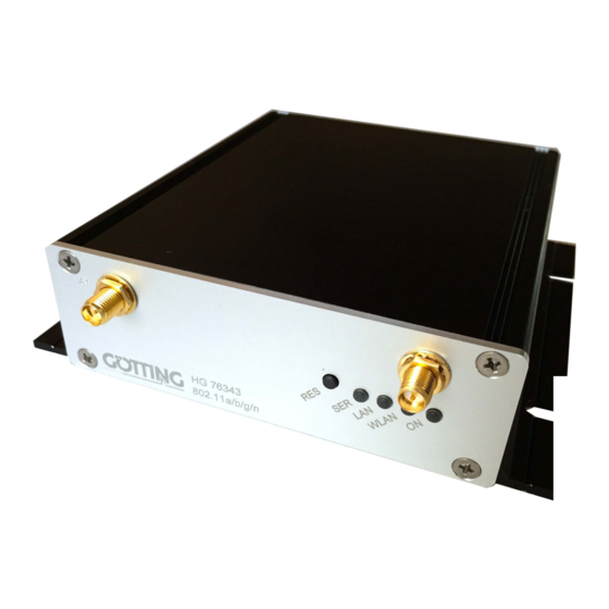
Gotting HG G-76343 Manual (126 pages)
WLAN Radio Modem 802.11 a/b/g/n
Brand:
Gotting
| Category:
Modem
| Size: 7 MB
Table of Contents
Table of Contents
3
About this Document
7
Presentation of Information
7
Table 1 Hazard Classification According to ANSI Z535.6-2006
7
Warning Notices
7
Declaration of Conformity
8
Symbols
8
Figure 1 Complete System (Example)
9
Introduction
9
Interfaces
10
Table 2 Variants of the Radio Modem
10
Versions / Variants
10
Connectors HG G-76343-A
11
Figure 2 All Variants: Connectors and Indicators on the Front Panel
11
Figure 3 Connectors HG G-76343ZA
11
Indicators and Connectors
11
Connectors HG G-76344-A
12
Connectors HG G-76345-A
12
Figure 4 Connectors HG G-76344ZA
12
Figure 5 Connectors HG G-76345ZA
12
Figure 6 Pin Assignment 5 Pin. M12 Socket Power & Relay
12
Pin Assignments
12
Pin M12 Socket Power & Relay
12
Figure 7 Leds
13
Leds
13
Pin Sub-D Socket Serial
13
Table 3 Pin Assignment 9 Pin Sub-D Socket
13
Table 4 Functions of the Leds
13
Casing Type XA with Top hat Rail Mounting on Narrow Side (All Vari- Ants)
15
Casing Type YA with Top hat Rail Mounting on Broad Side
15
Commissioning
15
Figure 8 Dimensions Casing Type XA
15
Figure 9 Dimensions Casing Type YA
15
Mounting
15
Casing Type ZA with Flange Casing
16
Figure 10 Dimensions Casing Type ZA
16
Initial Startup Via LAN
16
Commissioning Via the Web Interface
17
Reset to Factory Settings
17
The MC-Config Program
17
Encrypted Transmission
18
Functional Description
18
IP Protocols and Ports Used
18
MC-Config Program
18
Figure 11 MC-Config Program: Setup for the Initial Operation of a WLAN Client
19
Figure 12 Initial Commissioning with the MC-Config Program
19
Initial Startup
19
Figure 13 MC-Config Program: User Interface
20
Figure 14 MC-Config Program: Operating Elements
20
Operating Elements
20
Operation
20
Table 5 MC-Config Program: Operating Elements
20
Figure 15 MC-Config Program: List View Items
21
Information Shown by the List View Items
21
Table 6 MC-Config Program: Information in the List View
21
Table 7 Color Coding Connection Type IP Address
22
Arrangement of Columns
23
Figure 16 MC-Config Program: List View Items
24
Settings for the Logging of Messages
24
Table 8 MC-Config Program: Logging Settings
24
Context Menu of the List Items
25
Figure 17 MC-Config Program: List Context Menu Items
25
Table 9 MC-Config Program: List Context Menu Items
25
Figure 18 MC-Config Program: File Menu
26
File
26
Menus
26
Configure
27
Figure 19 MC-Config Program: View Menu
27
Figure 20 MC-Config Program: Configure Menu
27
Table 10 MC-Config Program: Functions of the View Menu
27
Table 11 MC-Config Program: Functions of the Configure Menu
27
View
27
Table 12 MC-Config Program: Key Shortcuts
28
Table 13 MC-Config Program: Device Polling
29
Table 14 MC-Config Program: Pretest
30
Device
31
Figure 21 MC-Config Program: Device Menu
31
Table 15 MC-Config Program: Functions of the Device Menu
31
Figure 22 MC-Config Program: Config Dialog
32
The Config Function
32
Access Protection with Username and Password
33
Figure 23 MC-Config Program: Enter Username and Password
33
Table 16 MC-Config Program: Buttons of the Config Dialog
33
Variable Number of Input Fields
33
Downloading the Config from Multiple Devices
34
Figure 24 MC-Config Program: Dialogs While Downloading the Config from Multi
34
Firmware-Updates
34
IP Ranges
34
Search WLAN Clients
34
Figure 25 MC-Config Program: IP Ranges
35
Figure 26 MC-Config Program: IP Search Range
35
Configuration of the Logging Parameters
36
Figure 27 MC-Config Program: Configuration of the Logging Details
36
Logging System Messages
36
Download of Debug Messages and (W)LAN Logs
37
Figure 28 MC-Config Program: Recording Debug Messages
37
Figure 29 MC-Config Program: Download Dumps and Log
37
Recording Debug Messages
37
Figure 30 Web Interface: System Information
38
Information Site / Home
38
Parameter Setting Via the Web Interface
38
System Information
38
Table 17 Web Interface: System Information
38
Figure 31 Web Interface: Wireless Status Information
39
Table 18 Web Interface: Wireless Status Information
39
Wireless Status Information
39
Table 19 Web Interface: Possible Messages Connection State
40
Table 20 Web Interface: Display for Active Encryption
40
Table 21 Web Interface: SNR Quality of the Reception Signal
41
Figure 32 Web Interface: Wired LAN Status Information
42
Table 22 Web Interface: Wired LAN Status Information
42
Wired LAN Status Information
42
Figure 33 Web Interface: Serial1 Status Information
43
Serial1
43
Table 23 Web Interface: Serial1
43
Relay Status Information / IO-Info (Optional)
44
Table 24 Web Interface: Relay Status Information / IO-Info (Optional)
44
Table 25 Web Interface: Operating Modes Relay
44
Access Point Information
45
Figure 34 Web Interface: Access Point List
45
Network Information
45
Table 26 Web Interface: Network Information
45
Figure 35 Web Interface: Storage Status Information
46
HTTPS Webinterface
46
Storage Status Information
46
Device Menu (Firmware and Configuration Management)
47
Figure 36 Wireless Dump / Ethernet Dump File List
47
Figure 37 Web Interface: Firmware Upload Dialog
47
Firmware
47
WLAN and LAN Dump Files
47
Configuration Management
48
Figure 38 Web Interface: Configuration Management
48
Network Test
48
Table 27 Web Interface: Configuration Management
48
Configuration (of the Operating Parameters)
49
Table 28 Web Interface: Network Test
49
Table 29 Web Interface: Configuration Menus
49
Admin Menu
50
Figure 40 Web Interface: Admin Page
50
Figure 41 Web Interface: Network > IP Settings
51
Figure 42 Web Interface: Network > Gateway Settings
51
IP Address
51
Network Menu
51
Bridge
52
Figure 43 Web Interface: Network > IPV6 Settings
52
Figure 44 Web Interface: Network > Mdns Settings
52
IPV6 Settings (Experimental)
52
Mdns Settings
52
MQTT Client
52
Figure 45 Web Interface: Printer Server Configuration
53
Printer Server
53
Serial Port
53
Wireless / Parameters of WLAN Interface
53
Relay
54
Relay Parameter
54
Table 30 Web Interface: Onboard Relay
54
Table 31 Web Interface: Relay Modes
54
Delayed Switching on and off of the Relay
55
Input (Optional)
55
Logging (Debug)
55
Realtime Clock
55
Table 32 Web Interface: Realtime Clock
55
Figure 46 Web Interface: Example for a System Log Output
56
Statistics
56
Statistics - Network
56
Statistics - System Log
56
Figure 47 Web Interface: Example for a Statistics Network Output
57
Support
57
Bridge Modes
58
Bridge Not Active Mode
58
Table 33 Bridge Modes
58
Figure 48 Bridge Modes: Bridge off
59
LAN Client Cloning
59
Figure 49 Bridge Modes: LAN Client Cloning Parameters 1
60
Figure 50 Bridge Modes: LAN Client Cloning Parameters 2
60
Figure 51 Bridge Modes: Example for LAN Client Cloning
61
Figure 52 Bridge Modes: NAT Mode (Example Configuration)
61
NAT and Single Client NAT Mode
61
Figure 53 Bridge Modes: Single Client NAT Mode
62
Figure 54 Bridge Modes: Forwarding Rules for NAT
63
Forwarding Rules for NAT
63
DHCP Server Settings
64
Figure 55 Bridge Modes: DHCP Server Settings
64
Figure 56 Bridge Modes: Static DHCP Server Entries
64
Static DHCP Server Entries
64
Figure 57 Bridge Modes: Level 2 Bridge Example Configuration
66
Figure 58 Bridge Modes: Level 2 Pseudo Bridge Mode
66
Level 2 Pseudo Bridge Mode
66
MWLC Mode
67
Figure 59 Bridge Modes: MWLC Mode Example Configuration
68
Figure 60 Bridge Modes: MWLC Master
69
Figure 61 Bridge Modes: MWLC Slave
69
MWLC Master
69
MWLC Slave
69
MQTT Client
70
Table 34 MQTT Client: Variables
70
Table 35 MQTT Client: Parameter
70
Table 36 Wireless (WLAN Interface): Wireless Sub Menus
72
Wireless (WLAN Interface)
72
Figure 62 Wireless (WLAN Interface): Wireless Parameters
73
Main Parameter
73
Figure 63 Wireless (WLAN Interface): Wireless Status Information Service
74
Table 37 Wireless (WLAN Interface): Variable Formats
74
Wireless Status Information Service
74
Profile Change Action
75
SSID Profile
75
Table 38 Wireless (WLAN Interface): SSID Profile Parameters
75
Table 39 Wireless (WLAN Interface): SSID Profile Change Action
75
Wireless SSID Profile
75
Connect Action
76
Table 40 Wireless (WLAN Interface): SSID Connect Action
76
Security Parameters
77
Table 41 Wireless (WLAN Interface): Wireless Security Parameters
77
Table 42 Wireless (WLAN Interface): Encryption Mode
77
Table 43 Wireless (WLAN Interface): Keying Protocol
77
Eap
78
Table 44 Wireless (WLAN Interface): EAP Parameters
78
Table 45 Wireless (WLAN Interface): EAP Type
78
Certificates
79
Roaming Parameter
79
Scep
79
Table 46 Wireless (WLAN Interface): Certificates Parameter
79
Wireless Roaming
79
AP Density
80
AP Scoring
80
Channels for Roaming
80
Max Scan Interval
80
Min Scan Interval
80
Table 47 Wireless (WLAN Interface): AP Density
80
Background Scanning
81
Blacklist Timer
81
Connection Watchdog
81
Figure 64 Wireless (WLAN Interface): Enable Ping
81
Ping Test
81
Table 48 Wireless (WLAN Interface): Background Scanning
81
Figure 65 Wireless (WLAN Interface): Preferred/Avoided Access Points
82
Preferred / Avoided Access Points
82
Table 49 Wireless (WLAN Interface): Ping Options
82
Parameters of the Serial Interface
83
Serial Interface
83
Table 50 Serial Interface: Serial Port Parameters
83
Table 51 Criteria for Sending of Characters
83
Handshake Mode Settings
84
Keep Alive Settings
84
Network-Configuration Modes
84
Enable Dump
85
Debug / Logging
86
Figure 66 Debug / Logging: Debug Log Page
86
Record System Messages
86
Figure 67 Debug / Logging: Log File Destination
87
Figure 68 Debug / Logging: Debug Information
87
Set Additional Debug Information
87
Setting the Debug File Destination
87
Table 52 Debug / Logging: Log File Destinations
87
Table 53 Debug / Logging: Debug Information
87
Figure 69 Debug / Logging: Syslog Server
88
Syslog Server
88
Table 54 Debug / Logging: Elements of a Debug Log Output Line
88
Figure 70 Debug / Logging: Traffic Dump Configuration
89
Table 55 Debug / Logging: Traffic Dump Configuration
89
Traffic Dump Configuration (Recording of Data Traffic from the LAN or WLAN Interface)
89
Figure 71 Debug / Logging: Wireless Dump / Ethernet Dump File List
90
Downloading Debug Files with the MC-Config Program
91
Figure 72 Debug / Logging: MC-Config Download Dumps and Log
91
Figure 73 Debug / Logging: MC-Config: Download Dumps and Debug Logs
91
Debug Configurations
92
Table 56 Debug / Logging: Structure of the File Names of the Downloaded Dump Files
92
Table 57 Debug / Logging: Debug Levels
92
Figure 74 Debug / Logging: Syslog Server
93
Table 58 Debug / Logging: Individual Debug Levels
93
Table 59 Debug / Logging: Intensity of the Debug Messages
94
Application for the Config-USB-Stick
95
Configuration with USB Memory Stick
95
Initializing a Config-USB-Stick
95
Transfer of a Configuration File During a Default Reset
95
Figure 75 USB-Config-Stick: MC-Config Init with USB Stick Config
96
Functions and Command Lines
97
Rest-Api
97
Table 60 REST-API: Functions and Parameters
97
Table 61 REST-API: Curl Command Lines
98
Figure 76 Example of REST API Status Output (IP and Mac Addresses Set to 0)
99
Outputs for the Status Function
99
Hardware
102
Table 62 Technical Data Hardware
102
Technical Data
102
Output Power & Sensitivity
103
Table 63 Technical Data WLAN Interface
103
Table 64 Technical Data - Output Power & Sensitivity 802.11B
103
Table 65 Technical Data - Output Power & Sensitivity 802.11A
103
Table 66 Technical Data - Output Power & Sensitivity 802.11G
103
Table 67 Technical Data - Output Power & Sensitivity 802.11N / 2,4 Ghz
103
WLAN Interface
103
Table 68 Technical Data - Output Power & Sensitivity 802.11N / 5 Ghz
104
Figure 77 Application Example HG G-76342/4/5-A Ac
105
HG G-76343/4/5-A Ac (802.11Ac)
105
Output Power and Sensitivity
106
Table 69 Technical Data HG G-76342/4/5-A Ac - WLAN Interface
106
Table 70 Technical Data HG G-76342/4/5-A Ac - Output Power and Sensitivity
106
Technical Data HG G-76342/4/5-A Ac
106
WLAN Interface
106
Figure 78 Application Example HG G-76344-A LTE
107
Hg G-76344Xa/Za 4G Lte 5G
107
Table 71 Variants of the Radio Modem with Mobile Radio Interface
107
Variants HG G-76344-A LTE
107
Connectors
108
Figure 79 Front Panel Connections of the HG G-76344-A LTE Variants
108
Mobile Radio Interface
108
Table 72 Functions of the Mobile Radio Interfaces HG G-76344-A LTE
108
Use as an LTE Router
108
Figure 80 Position of the SIM Card Slot (in the Picture HG G-76344ZA LTE-5G)
109
How to Insert the SIM Card
109
Figure 81 Position of the LTE LED (in the Picture HG G-76344ZA LTE-5G)
110
Lte Led
110
Table 73 Functions of the LTE LED
110
Additional Outputs in the Web Interface
111
Figure 82 LTE Information in the Web Interface
111
Mobile Radio Status
111
Table 74 LTE Mobile Radio Status Info in the Web Interface
111
Figure 83 Input of the Mobile Radio Parameters Via MC-Config (Left) or the Web In- Terface (Right)
112
Input of the Parameters for the Cellular Connection
112
Network Information
112
Table 75 LTE Network Information in the Web Interface
112
Rest-Api
113
Table 76 Parameters of the Mobile Connection
113
Table 77 REST-API: LTE Status
113
Table 78 Technical Data Mobile Radio Interface
114
Technical Data
114
Open Source Compliance Information
115
Information for Host Integrators of the Radio Module
116
Information to End User
116
Labelling Instructions for Host Devices
116
RF Exposure / Collocation Requirements
116
Statements and Instructions According to FCC and Industry Canada Rules
116
FCC and Industry Canada Warning Statements and Special Instructions
117
- List of Figures
118
Chapter 18 List of Figures
118
Chapter 19 List of Tables
120
Index
122
Copyright and Terms of Liability
125
Copyright
125
Exclusion of Liability
125
Trade Marks and Company Names
125
Advertisement
Gotting HG G-76343 Manual (114 pages)
WLAN Radio Modem 802.11 a/b/g/n
Brand:
Gotting
| Category:
Modem
| Size: 5 MB
Table of Contents
Table of Contents
3
About this Document
7
Presentation of Information
7
Table 1 Hazard Classification According to ANSI Z535.6-2006
7
Warning Notices
7
Declaration of Conformity
8
Symbols
8
Figure 1 Complete System (Example)
9
Introduction
9
Interfaces
10
Table 2 Variants of the Radio Modem
10
Versions / Variants
10
Connectors HG G-76343-A
11
Connectors HG G-76344-A
11
Figure 2 All Variants: Connectors and Indicators on the Front Panel
11
Figure 3 Connectors HG G-76343ZA
11
Figure 4 Connectors HG G-76344ZA
11
Indicators and Connectors
11
Connectors HG G-76345-A
12
Figure 5 Connectors HG G-76345ZA
12
Figure 6 Pin Assignment 5 Pin. M12 Socket Power & Relay
12
Pin Assignments
12
Pin M12 Socket Power & Relay
12
Pin Sub-D Socket Serial
12
Table 3 Pin Assignment 9 Pin Sub-D Socket
12
Figure 7 Leds
13
Leds
13
Table 4 Functions of the Leds
13
Casing Type XA with Top hat Rail Mounting on Narrow Side (All Vari- Ants)
14
Casing Type YA with Top hat Rail Mounting on Broad Side
14
Commissioning
14
Figure 8 Dimensions Casing Type XA
14
Figure 9 Dimensions Casing Type YA
14
Mounting
14
Casing Type ZA with Flange Casing
15
Figure 10 Dimensions Casing Type ZA
15
Initial Startup Via LAN
15
The MC-Config Program
15
Reset to Factory Settings
16
Figure 11 MC-Config Program: Setup for the Initial Operation of a WLAN Client
17
Functional Description
17
Initial Startup
17
MC-Config Program
17
Figure 12 MC-Config Program: User Interface
18
Figure 13 MC-Config Program: Operating Elements
18
Operating Elements
18
Operation
18
Table 5 MC-Config Program: Operating Elements
18
Figure 14 MC-Config Program: List View Items
19
Information Shown by the List View Items
19
Table 6 MC-Config Program: Information in the List View
19
Table 7 Color Coding Connection Type
20
Arrangement of Columns
21
Figure 15 MC-Config Program: List View Items
22
Settings for the Logging of Messages
22
Table 8 MC-Config Program: Logging Settings
22
Context Menu of the List Items
23
Figure 16 MC-Config Program: List Context Menu Items
23
Table 9 MC-Config Program: List Context Menu Items
23
Figure 17 MC-Config Program: File Menu
24
File
24
Menus
24
Configure
25
Figure 18 MC-Config Program: View Menu
25
Figure 19 MC-Config Program: Configure Menu
25
Table 10 MC-Config Program: Functions of the View Menu
25
Table 11 MC-Config Program: Functions of the Configure Menu
25
View
25
Table 12 MC-Config Program: Key Shortcuts
26
Table 13 MC-Config Program: Device Polling
26
Table 14 MC-Config Program: Pretest
27
Device
28
Figure 20 MC-Config Program: Device Menu
28
Table 15 MC-Config Program: Functions of the Device Menu
28
The Config Function
28
Figure 21 MC-Config Program: Config Dialog
29
Figure 22 MC-Config Program: IP Ranges
30
Firmware-Updates
30
IP Ranges
30
Search WLAN Clients
30
Table 16 MC-Config Program: Buttons of the Config Dialog
30
Configuration of the Debug Parameters
31
Figure 23 MC-Config Program: IP Search Range
31
Logging Debug Messages
31
Figure 24 MC-Config Program: Configuration of the Logging Details
32
Figure 25 MC-Config Program: Debug Logging
32
Start Debug Logging
32
Download of Debug Messages and (W)LAN Logs
33
Figure 26 MC-Config Program: Download Dumps and Log
33
Figure 27 Web Interface: System Information
34
Information Site / Home
34
Parameter Setting Via the Web Interface
34
System Information
34
Figure 28 Web Interface: Wireless Status Information
35
Table 17 Web Interface: System Information
35
Table 18 Web Interface: Wireless Status Information
35
Wireless Status Information
35
Table 19 Web Interface: Possible Messages Connection State
36
Table 20 Web Interface: Display for Active Encryption
36
Figure 29 Web Interface: Wired LAN Status Information
37
Table 21 Web Interface: SNR Quality of the Reception Signal
37
Table 22 Web Interface: Wired LAN Status Information
37
Wired LAN Status Information
37
Figure 30 Web Interface: Serial1 Status Information
38
Serial1
38
Table 23 Web Interface: Serial1
38
Relay Status Information / IO-Info (Optional)
39
Table 24 Web Interface: Relay Status Information / IO-Info (Optional)
39
Table 25 Web Interface: Operating Modes Relay
39
Table 26 Web Interface: Operating Modes AUX Input
39
Access Point Information
40
Figure 31 Web Interface: Access Point List
40
Network Information
40
Table 27 Web Interface: Network Information
40
Figure 32 Web Interface: Storage Status Information
41
HTTPS Webinterface
41
Storage Status Information
41
Device Menu (Firmware and Configuration Management)
42
Figure 33 Web Interface: Firmware-Upload
42
Firmware
42
Configuration (of the Operating Parameters)
43
Configuration Management
43
Figure 34 Web Interface: Configuration Management
43
Table 28 Web Interface: Configuration Management
43
Admin Menu
44
Figure 35 Web Interface: Admin Page
44
Table 29 Web Interface: Configuration Menus
44
Figure 36 Web Interface: Network > IP Settings
45
IP Address
45
Network Menu
45
Bridge
46
Figure 37 Web Interface: Network > IPV6 Settings
46
Figure 38 Web Interface: Network > Mdns Settings
46
IPV6 Settings (Experimental)
46
Mdns Settings
46
Wireless / Parameters of WLAN Interface
46
Figure 39 Web Interface: Printer Server Configuration
47
Printer Server
47
Relay
47
Relay Parameter
47
Serial Port
47
Table 31 Web Interface: Relay Modes
47
Delayed Switching on and off of the Relay
48
Realtime Clock
48
Table 30 Web Interface: Onboard Relay
48
Table 32 Web Interface: Realtime Clock
48
Input (Optional)
49
Input Parameters
49
Table 34 Web Interface: AUX Input Modes
49
Figure 40 Web Interface: Example for a System Log Output
50
Input Query in UDP Mode
50
Logging (Debug)
50
Statistics
50
Statistics - System Log
50
Table 33 Web Interface: AUX Input Parameters
50
Figure 41 Web Interface: Example for a Statistics Network Output
51
Statistics - Network
51
Support
51
Bridge Modes
52
LAN Client Cloning
52
Table 35 Bridge Modes
52
Figure 42 Bridge Modes: LAN Client Cloning Parameters 1
53
Figure 43 Bridge Modes: LAN Client Cloning Parameters 2
53
Figure 44 Bridge Modes: Example for LAN Client Cloning
54
Figure 45 Bridge Modes: NAT Mode (Example Configuration)
54
NAT and Single Client NAT Mode
54
Figure 46 Bridge Modes: Single Client NAT Mode
55
Figure 47 Bridge Modes: Forwarding Rules for NAT
56
Forwarding Rules for NAT
56
DHCP Server Settings
57
Figure 48 Bridge Modes: DHCP Server Settings
57
Figure 49 Bridge Modes: Static DHCP Server Entries
57
Static DHCP Server Entries
57
Level 2 Pseudo Bridge Mode
58
Figure 50 Bridge Modes: Level 2 Bridge Example Configuration
59
Figure 51 Bridge Modes: Level 2 Pseudo Bridge Mode
59
Figure 52 Bridge Modes: MWLC Mode Example Configuration
60
MWLC Mode
60
Figure 53 Bridge Modes: MWLC Master
61
Figure 54 Bridge Modes: MWLC Slave
61
MWLC Master
61
MWLC Slave
61
Bridge Not Active Mode
62
Figure 55 Bridge Modes: Bridge Not Active
62
Table 36 WLAN Interface: Wireless Sub Menus
63
Wireless (WLAN Interface)
63
Figure 56 Wireless (WLAN Interface): Wireless Parameters
64
Main Parameter
64
Figure 57 Wireless (WLAN Interface): Wireless Status Information Service
65
Table 37 Wireless (WLAN Interface): Variable Formats
65
Wireless Status Information Service
65
Profile Change Action
66
SSID Profile
66
Table 38 Wireless (WLAN Interface): SSID Profile Parameters
66
Table 39 Wireless (WLAN Interface): SSID Profile Change Action
66
Wireless SSID Profile
66
Connect Action
67
Table 40 Wireless (WLAN Interface): SSID Connect Action
67
Security Parameters
68
Table 41 Wireless (WLAN Interface): Wireless Security Parameters
68
Table 42 Wireless (WLAN Interface): Encryption Mode
68
Table 43 Wireless (WLAN Interface): Keying Protocol
68
Eap
69
Table 44 Wireless (WLAN Interface): EAP Parameters
69
Table 45 Wireless (WLAN Interface): EAP Type
69
Certificates
70
Roaming Parameter
70
Scep
70
Table 46 Wireless (WLAN Interface): Certificates Parameter
70
Wireless Roaming
70
AP Density
71
AP Scoring
71
Channels for Roaming
71
Max Scan Interval
71
Min Scan Interval
71
Table 47 Wireless (WLAN Interface): AP Density
71
Background Scanning
72
Blacklist Timer
72
Connection Watchdog
72
Figure 58 Wireless (WLAN Interface): Enable Ping
72
Ping Test
72
Table 48 Wireless (WLAN Interface): Background Scanning
72
Figure 59 Wireless (WLAN Interface): Preferred/Avoided Access Points
73
Preferred / Avoided Access Points
73
Table 49 Wireless (WLAN Interface): Ping Options
73
Parameters of the Serial Interface
74
Serial Interface
74
Table 50 Serial Interface: Serial Port Parameters
74
Table 51 Criteria for Sending of Characters
74
Handshake Mode Settings
75
Keep Alive Settings
75
Network-Configuration Modes
75
Enable Dump
76
Debug / Logging
77
Figure 60 Debug / Logging: Debug Log Page
77
Record System Messages
77
Figure 61 Debug / Logging: Log File Destination
78
Figure 62 Debug / Logging: Debug Information
78
Set Additional Debug Information
78
Setting the Debug File Destination
78
Table 52 Debug / Logging: Log File Destinations
78
Table 53 Debug / Logging: Debug Information
78
Figure 63 Debug / Logging: Syslog Server
79
Syslog Server
79
Table 54 Debug / Logging: Elements of a Debug Log Output Line
79
Figure 64 Debug / Logging: Traffic Dump Configuration
80
Table 55 Debug / Logging: Traffic Dump Configuration
80
Traffic Dump Configuration (Recording of Data Traffic from the LAN or WLAN Interface)
80
Downloading Debug Files with the MC-Config Program
81
Figure 65 Debug / Logging: Wireless Dump / Ethernet Dump File List
81
Figure 66 Debug / Logging: MC-Config Download Dumps and Log
81
Figure 67 Debug / Logging: MC-Config: Download Dumps and Debug Logs
82
Table 56 Debug / Logging: Structure of the File Names of the Downloaded Dump Files
82
Debug Configurations
83
Figure 68 Debug / Logging: Syslog Server
83
Table 57 Debug / Logging: Debug Levels
83
Table 58 Debug / Logging: Individual Debug Levels
83
Table 59 Debug / Logging: Intensity of the Debug Messages
84
Application for the Config-USB-Stick
85
Configuration with USB Memory Stick
85
Initializing a Config-USB-Stick
85
Transfer of a Configuration File During a Default Reset
85
Figure 69 USB-Config-Stick: MC-Config Init with USB Stick Config
86
Functions and Command Lines
87
Rest-Api
87
Table 60 REST-API: Functions and Parameters
87
Table 61 REST-API: Curl Command Lines
88
Outputs for the Status Function
89
Table 62 REST API: Return Values Api/Status/Device
89
Table 63 REST API: Return Calues Api/Status/Serial
89
Table 64 REST API: Return Values Api/Status/Relay
90
Table 65 REST API: Return Values Api/Status/Wireless
90
Hardware
92
Table 66 Technical Data Hardware
92
Technical Data
92
Table 67 Technical Data WLAN Interface
93
WLAN Interface
93
Figure 70 Application Example HG G-76344-A LTE
94
Hg G-76344Xa/Za 4G Lte 5G
94
Table 68 Variants of the Radio Modem with Mobile Radio Interface
94
Variants HG G-76344-A LTE
94
Connectors
95
Figure 71 Front Panel Connections of the HG G-76344-A LTE Variants
95
Mobile Radio Interface
95
Table 69 Functions of the Mobile Radio Interfaces HG G-76344-A LTE
95
Use as an LTE Router
95
Figure 72 Position of the SIM Card Slot (in the Picture HG G-76344ZA LTE-5G)
96
How to Insert the SIM Card
96
Figure 73 Position of the LTE LED (in the Picture HG G-76344ZA LTE-5G)
97
Lte Led
97
Table 70 Functions of the LTE LED
97
Additional Outputs in the Web Interface
98
Figure 74 LTE Information in the Web Interface
98
Mobile Radio Status
98
Table 71 LTE Mobile Radio Status Info in the Web Interface
98
Figure 75 Input of the Mobile Radio Parameters Via MC-Config (Left) or the Web Interface (Right)
99
Input of the Parameters for the Cellular Connection
99
Network Information
99
Table 72 LTE Network Information in the Web Interface
99
Table 73 Parameters of the Mobile Connection
99
Rest-Api
100
Table 74 REST-API: LTE Status
100
Table 75 Technical Data Mobile Radio Interface
101
Technical Data
101
Open Source Compliance Information
102
Information for Host Integrators of the Radio Module
103
Information to End User
103
Labelling Instructions for Host Devices
103
RF Exposure / Collocation Requirements
103
Statements and Instructions According to FCC and Industry Canada Rules
103
FCC and Industry Canada Warning Statements and Special Instructions
104
List of Figures - Chapter 16 105 List of Figures
105
Chapter 16 List of Figures
105
Chapter 17 List of Tables
107
Index
109
Copyright and Terms of Liability
112
Copyright
112
Exclusion of Liability
112
Trade Marks and Company Names
112
Advertisement
Related Products
Gotting HG G-76344
Gotting HG G-76345
Gotting HG 76342-A
Gotting HG G-73650-A
Gotting HG G-71910-C
Gotting HG G-71912-A
Gotting HG G-71450-A
Gotting HG G-71451-A
Gotting HG G-71453-A
Gotting HG G-71455-A
Gotting Categories
Antenna
GPS
Accessories
Controller
Marine Radio
More Gotting Manuals
Login
Sign In
OR
Sign in with Facebook
Sign in with Google
Upload manual
Upload from disk
Upload from URL