Sign In
Upload
Manuals
Brands
Geokon Manuals
Accessories
4100-9
Geokon 4100-9 Manuals
Manuals and User Guides for Geokon 4100-9. We have
1
Geokon 4100-9 manual available for free PDF download: Instruction Manual
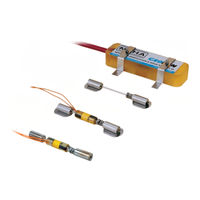
Geokon 4100-9 Instruction Manual (48 pages)
Vibrating Wire Strain Gauges
Brand:
Geokon
| Category:
Accessories
| Size: 2.38 MB
Table of Contents
Table of Contents
5
Introduction
11
Figure 1: Model 4100 Vibrating Wire Strain Gauge
11
Figure 2: Model 4150 Vibrating Wire Strain Gauge
12
Figure 3: Model 4151 Vibrating Wire Strain Gauge
12
Preliminary Checks
13
Using a Readout
13
Using an Ohmmeter
13
Instrument Protection
14
Cable Splicing and Termination
14
Protection from Mechanical Damage
14
Securing Cables
14
Cover Plates
14
Figure 4: Model 4100 Cover Plate - Top View
15
Figure 5: Model 4150 Cover Plate - Top View
15
Figure 6: Cover Plate - End View
15
Cable and Connector Protection
16
Protection from Corrosion
16
Figure 7: Cover Plate Installation, Top View
16
Figure 8: Cover Plate Installation, Side View
16
Protection from Electrical Noise
17
Protection from Sunlight and Temperature Changes
17
Lightning Protection
17
Figure 9: Lightning Protection Scheme
18
Gauge Installation
19
Adjusting the Gauge Wire Tension
19
Installing the 4100/4150 Via Spot Welding
19
Prepare the Surface
19
Spot Weld Test Strips
19
Table 1: Guide to Initial Tension Settings
19
Spot Welding the 4100 Gauge
20
Spot Welding the 4150 Gauge
20
Figure 10: Peel Test
20
Figure 11: Spot-Welding Sequence, Outer Rows (4100)
20
Figure 12: Spot Welding Sequence, Outer Rows (4150)
20
Welding the Second End Piece
21
Installing Collar Shims
21
Figure 13: Spot Welding Sequence, Inner Rows
21
Figure 14: Using the Alignment Tool
21
Figure 15: Collar Shim
22
Figure 16: Welding the Collar Shim in Place
22
Figure 17: Completed Collar Shim
22
Installing the Plucking Coil Housing (Model 4100 Only)
23
Installing the Gauge Cover (Model 4150 Only)
23
Securing the 4150 Gauge Cable
23
Installing the 4100/4150 Via Epoxy Bonding
23
Figure 18: Spot Welded Cover Plate
23
Installing the 4151 Strain Gauge
25
Figure 19: Model 4151 Strain Gauge Installation
25
Gauge Location
26
End Effects
26
Welding Effects
26
Bending Moments
26
Figure 20: Strain Gauges Mounted on Central Web
26
Equation 1: Axial Stress Calculation
27
Equation 2: Stress Due to Bending on Axis Yy
27
Equation 3: Stress Due to Bending on Axis XX
27
Equation 4: Maximum Stress
27
Figure 21: Strain Gauges Mounted on Flanges
28
Figure 22: Axial Strain Measurement/Bending Moment about Yy Axis
28
Figure 23: Axial Strain and Bending Moment about XX Axis
29
Figure 24: Axial Strain and Bending Moment about Axis
29
Taking Readings
30
Strain Gauge Readout Positions
30
Gk-404 Vibrating Wire Readout
30
Operating the Gk-404
30
Figure 25: Gk-404 Readout
30
Figure 26: Lemo Connector to Gk-404
30
Table 2: Strain Gauge Readout Positions
30
Gk-405 Vibrating Wire Readout
31
Connecting Sensors with 10-Pin Bulkhead Connectors Attached
31
Connecting Sensors with Bare Leads
31
Operating the Gk-405
31
Figure 27: Gk-405 Readout
31
Measuring Temperatures
32
Data Reduction
33
Conversion of the Readings to Strain Changes
33
Converting Strains to Stresses
33
Equation 5: Theoretical Microstrain
33
Equation 6: Strain Calculation
33
Troubleshooting
34
Appendix A. Specifications
35
Vibrating Wire Strain Gauge
35
Thermistor
35
Figure 28: Gauge Assembly Dimensions
35
Figure 29: Cover Assembly Dimensions
35
Table 3: Specifications
35
Appendix B. Theory of Operation
36
Appendix C. Thermistor Temperature Derivation
38
3Kω Thermistor Resistance
38
Table 4: 3Kω Thermistor Resistance
38
Equation 7: 3Kω Thermistor Resistance
38
10Kω Thermistor Resistance
39
Table 5: 10Kω Thermistor Resistance
39
Equation 8: 10Kω Thermistor Resistance
39
Appendix D. Temperature Correction When Used on Concrete
40
Equation 9: Thermal Concrete Strains
40
Equation 10: Actual Strain
40
Equation 11: Strain Due to Load Changes Only
40
Appendix E. Temperature Effects
41
Equation 12: External Load Stress Only
41
Equation 13: Free Field Thermal Strains
41
Equation 14: Actual Strain
41
Appendix F. Calculations from Three Strain Gauges
42
Figure 30: Three Strain Gauges Mounted on a Circular Pipe
42
Equation 15: Average Axial Strain
42
Equation 16: Maximum Bending Strain Around the Yy Axis
42
Equation 17: Maximum Bending Strain Around the XX Axis
42
Equation 18: Maximum Strain
42
Appendix G. Model 4150-5 Extended Range Strain Gauge
43
Equation 19: Model 4150-5 Temperature Effects
43
Appendix H. Parts List
44
Table 6: Model 4100/4150 Series Model and Parts List
44
Advertisement
Advertisement
Related Products
Geokon 4600
Geokon 4900
Geokon 4500HT-9-5
Geokon 4100 Series
Geokon 4150 Series
Geokon 4151
Geokon 4150-5
Geokon 4100-8
Geokon 4150-4
Geokon 4410
Geokon Categories
Measuring Instruments
Accessories
Data Loggers
Network Hardware
Industrial Equipment
More Geokon Manuals
Login
Sign In
OR
Sign in with Facebook
Sign in with Google
Upload manual
Upload from disk
Upload from URL